Influence of water environment on paint removal and the selection criteria of laser parameters
2022-06-29LiJunZhang张丽君KaiNanZhou周凯南GuoYingFeng冯国英JingHuaHan韩敬华NaXie谢娜andJingXiao肖婧
Li-Jun Zhang(张丽君) Kai-Nan Zhou(周凯南) Guo-Ying Feng(冯国英) Jing-Hua Han(韩敬华)Na Xie(谢娜) and Jing Xiao(肖婧)
1College of Electronics and Information Engineering,Sichuan University,Chengdu 610065,China
2Laser Fusion Research Center,China Academy of Engineering Physics,Mianyang 621999,China
3Science and Technology on Plasma Physics Laboratory,Mianyang 621999,China
4Southwest Institute of Technical Physics,Chengdu 610041,China
Keywords: paint removal by laser,water environment,thermal stress,laser plasma
1. Introduction
In recent years, with the rapid development of optical technology and improvement of laser performance,removal of large areas of paint using lasers has become possible. Certain objects that have been in a water environment for extended periods of time, such as ships and large bridges, suffer from surface coatings peeling off due to water erosion,and require regular maintenance and repair. To avoid affecting the quality of the new paint layer,the original paint layer needs to be cleaned; however, the cleanliness of the substrate affects the service life of steel products.[1,2]
Traditional paint removal methods are primarily mechanical or chemical in nature. Mechanical and physical methods refer to sand blasting or steel brush polishing, which are time-consuming and laborious,and often result in irreversible damage to the substrate. Chemical methods use chemical solvents to cause the paint layer to swell and then dissolve,which is costly and causes secondary pollution to the environment.Further,they are unsuitable for partial paint removal.[3]Compared to the traditional paint removal methods,the laser paint removal method eliminates the need for direct mechanical contact with the material,and can be accurately positioned on the surface of the material to be cleaned, saving time and effort,realizing zero emission and no pollution.[4]Schweizeret al.[5]used three CO2lasers to completely remove an aircraft paint layer with a surface area of 1600 m2and a thickness of 100 μm in just three days. Jasimet al.[6]used ns pulsed fiber laser to study the laser paint stripping of white polymer paint and aluminum alloy substrate. The results show that although the transparency of paint is very high, it can still achieve a high percentage of removal. And laser paint removal causes less damage to the substrate. Zhuet al.[7]studied the cleaning effect of Nd:YAG laser on BMS10-11 coating of Boeing series aircraft skin,and proved that laser would not reduce the hardness, corrosion resistance and friction and wear performance of aircraft skin surface. At the same time, scholars in worldwide have also conducted in-depth research on adding constraint layer in laser paint removal. Fox[8]coated resin glass and metal substrates with paint,and placed them in a water environment. When irradiated with aQ-switched neodymiumdoped glass laser, they found that the stress oscillation wave in the paint layer material was enhanced because the water layer effectively restrained the shock wave,which could effectively remove the paint layer. Tsunemiet al.[9]used a pulsed TEA CO2laser with a wavelength of 1.06 μm to remove paint from a metal substrate. They proved that a small amount of paint/residue layer that still remained on the surface could be effectively removed by liquid-assisted laser irradiation by using dimethylformamide. Yuvrajet al.[10]effectively removed paint and residual ash by using a high-power fiber laser beam with a wavelength of 1.07 μm coupled with a water jet. Compared to a gas-assisted laser paint removal process,they found that though the water jet-assisted laser paint removal required a higher specific energy,it could completely remove the paint without any ash.
However,most of the current research focuses on the experimental observation that the pressure applied on the sample is increased after adding a liquid confinement layer to improve the cleaning effect, while the theory of paint removal under laser-induced high temperature and pressure is still relatively weak. Therefore, in this study, based on the paint removal morphology under different laser fluences in water and air environments, the mechanism of laser action on the paint layer and substrate in different environments are analyzed.The thermodynamic and laser plasma effects, temperature and stress fields distribution of the laser-cleaning paint layer in different environments are studied. Further,the propagation process of shock waves in the paint layer and substrate is simulated,and thereafter,the best laser fluence range for paint removal in water is proposed. This work can provide a reference for the removal of paint or attachments on large equipment or bridges underwater.
2. Experiment
2.1. Experimental setup
The experimental setup for the laser paint removal is shown in Fig.1. Nd:YAG pulsed laser was used along with a Gaussian output beam profile with a wavelength of 1064 nm,pulse width of 12 ns, frequency of 1 Hz, and output energy stability≤3%. Firstly, the pulsed laser was divided into two beams via a beam splitter(with ratio of transmitted energy to reflected energy of 8:2),one of which reached the energy meter to monitor the energy of the laser, while the other beam passed through a total reflection mirror with a wavelength of 1064 nm,and then was focused on the sample at the bottom of a water sink via a lens withf=20 cm.The sink was placed on a three-dimensional mobile platform controlled by a computer to precisely adjust the working height. The sample surface was irradiated with a single pulse laser. Thereafter the threedimensional platform was moved, while the laser energy was gradually changed,and the material removal morphology was observed under a microscope.
The sample used in this experiment was a metal aluminum plate with a thickness of 1 mm,on which a red acrylic paint film of thickness approximately 24 μm was uniformly sprayed. The energy meter used was from Ophir Company(model: PE25), with a measurement accuracy of±3%, and energy measurement range of 200 μJ–10 J.The ablation morphology of paint was observed and recorded via a microscope(Keyence,VHX-2000)or scanning electron microscope(SEM).
2.2. Paint removal morphology in air

Fig.2. Paint removal morphology under different laser fluence in air: (a)0.13 J/cm2;(b)0.24 J/cm2;(c)0.37 J/cm2;(d)0.49 J/cm2;(e)0.54 J/cm2;(f)0.54 J/cm2;(g)1.5 J/cm2;(h)1.9 J/cm2;(i)2.4 J/cm2.
Figure 2 shows the ablation morphology of the paint layer under different laser fluences in air. When the laser fluence is 0.13 J/cm2, the central area irradiated by the spot is ablated,but the ablation is shallow and the paint layer removed is negligible. For laser fluence of 0.24 J/cm2, a small part of the paint layer at the edge of the irradiated area broke with the substrate, and the crack is slightly away from the central ablation area. When the laser fluence is 0.37 J/cm2, the deeper paint layer is removed,and most of the edge of the irradiated area is cracked with the substrate. Further for laser fluence of 0.49 J/cm2,the paint on the irradiated edge is completely broken and separated from the substrate,and finally for laser fluence of 0.54 J/cm2,the paint began to fall off along the broken part,and some paint layers became thinner after vaporization,however,the substrate was not damaged. Figure 2(f)is an enlarged view of the fractured edge of the paint layer in Fig.2(e),which shows that the paint layer has clear cuts without melting marks,indicating that the paint layer broke before melting.When the laser fluence increases from 0.54 J/cm2to 1.5 J/cm2,the paint layer has been completely removed with substrate not being damaged. For the laser fluence of 1.9 J/cm2, the substrate in the irradiation center is damaged. Melting occurs,but the paint layer on the edge of the substrate without damage is still cracked and removed. Further for 2.4 J/cm2,the substrate damage is more obvious,and the magnified part of the damage shows that there is strong ablation and melting phenomenon on the surface. The molten metal on the surface of the substrate rapidly cools and solidifies, forming an uneven surface morphology. Considering the fracture mechanics, thermal stress plays a vital role in the paint removal process, and paint removal can be achieved by using this method. Under laser irradiation, the temperature of the substrate and the paint layer increases, and the paint layer undergoes phase changes such as melting and vaporization, resulting in a thermal stress difference at the interface between them,which eventually leads to paint layer fracture.
2.3. Paint removal morphology in water
Figure 3 shows the damage morphology when the sample is placed 1.6 cm underwater and irradiated with different laser fluences. It is evident that with the increase of laser fluence, the morphology of the removed paint layer is different:when the laser fluence is small(0.10 J/cm2),the paint is negligibly removed, but there are impact marks on the surface;for the laser fluence of 0.25 J/cm2, the paint in the center of the irradiated area is slightly removed;further for the laser fluence of 0.49 J/cm2and 0.53 J/cm2, the removal area of the irradiation center gradually increases without damage to the substrate; and finally for 0.65 J/cm2and 0.8 J/cm2, the paint removal area continues increasing,while the center of the bare substrate is damaged and the damage pits gradually increase.
In contrast to the damage pattern in air,when the sample was placed in water, the surface ablation marks were heavier than those in air,further the paint layer on the irradiated edge did not crack, but were only partially removed in the central area of the spot. When the laser fluence was 0.25 J/cm2in a water environment,the paint could be removed,while for the complete separation of paint from the substrate in air,the laser fluence was 0.49 J/cm2. Thus,the threshold for laser removal in water is smaller than that in air.
Scanning electron microscopy(SEM)and energy dispersive spectrometry (EDS) were used to characterize the morphology and elemental composition of the paint layer after the laser irradiation. The results are shown in Figs. 4–6, respectively. Figure 4(a)is the SEM images of the overall morphology when the paint is removed in the air for the laser fluence is 1.6 J/cm2. Figures 4(b), 4(c) and 4(d) are the morphology of part of the paint particles deposited on the substrate when the laser flux is 1.6 J/cm2, 1.9 J/cm2and 2.1 J/cm2, respectively. It is evident that the surface contains numerous condensed micro-nano particles.

Fig.3.Paint removal morphology under different laser fluences in water environment:(a)0.10 J/cm2;(b)0.25 J/cm2;(c)0.49 J/cm2;(d)0.53 J/cm2;(e)0.65 J/cm2;(f)0.8 J/cm2.

Fig.4. Morphology of paint layer removed in air: (a)overall morphology,1.6 J/cm2,(b)part I,(c)1.9 J/cm2,(d)2.1 J/cm2.
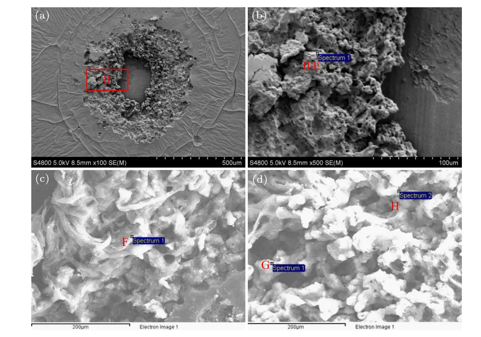
Fig.5. Morphology of paint layer removed in water: (a)overall morphology,0.49 J/cm2,(b)part II,(c)0.53 J/cm2,(d)0.65 J/cm2.
Figure 5(a) shows the overall morphology of paint removal in water when the laser fluence is 0.49 J/cm2, and Figs.5(b),5(c)and 5(d)show the morphology details of edge paint removal when the laser fluence is 0.49 J/cm2,0.53 J/cm2and 0.65 J/cm2,respectively.The paint surface is irregular and presents blocks of different shapes.
The quantitative proportion of paint element composition after paint removal reflects the basic mechanism of paint removal,and corresponding elemental composition and content are shown in Fig.6.
Figures 6 show that the main elements of the paint layer are C, O, Pb, and Cr, and the atomic number fraction ratio of each element changes before and after the paint removal,with the atomic fraction of C in the material accounting for the larger proportion. Elemental analysis shows that when paint is removed in air, the atomic number fraction of C decreases and the atomic number fraction of O increases,while in water,there is no obvious difference between the content of carbon and oxygen and the original paint layer.
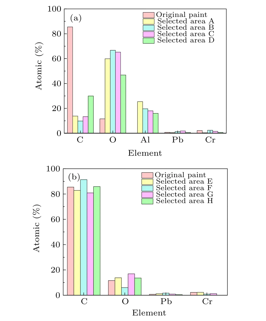
Fig. 6. Atomic ratio of elements after paint removal in different environments: (a)in air and(b)in water.
3. Theoretical analysis
Vibration,ablation,and laser plasma effects primarily occur during the laser paint removal.[11–13]The vibration effect indicates that when the pulsed laser irradiates the surface of the paint layer, the paint layer along with the substrate instantly heat up after absorbing the laser energy and thus produce thermal expansion,which leads to vibration waves within the surface of the paint layer and substrate,the stress formed at the interface overcomes the adhesion between the paint layer and substrate surface,and then breaks away from the substrate.Further,the ablation effect indicates that the temperature of the paint layer rises above the vaporization temperature after being irradiated by the laser,and thus the paint layer is removed by vaporization,and simultaneously,the vaporized steam continuously absorbs laser energy to increase its temperature,which results in the ionization of the paint forming high temperature and pressure laser plasma. This expands outward to form a laser plasma shock wave, causing shock damage to the paint,which is referred as the laser plasma effect. The physical essence of these three effects is that the laser heats the object and then produces thermal stress. The following three effects have been analyzed in the following sections.
3.1. Thermal effect
When the laser is irradiated on the surface of the sample,the paint and aluminum substrate absorb the laser energy to generate heat, and the temperature change conforms to the heat conduction equation. As the temperature increased, the substrate and paint layer began to expand,and the thermal expansion caused thermal stress on the sample. In order to analyze the temperature rise of paint and substrate under laser pulse irradiation, we make the following assumptions based on the primary process of laser action: (1)the distribution of laser intensity in the propagation direction follows the law of light absorption;(2)because the pulse laser irradiates the sample for a very short time (on the order of ns), the paint layer and substrate can be simplified as a one-dimensional infinite plane, and the absorption or diffusion of laser energy is considered adiabatic; (3)because the depth of heat conduction is far less than the laser radius, the heat transfer of laser energy can be regarded as a one-dimensional model;and(4)the heat conduction between the paint layer and the contact surface of the substrate is not considered. The effect model is illustrated in Fig.7.
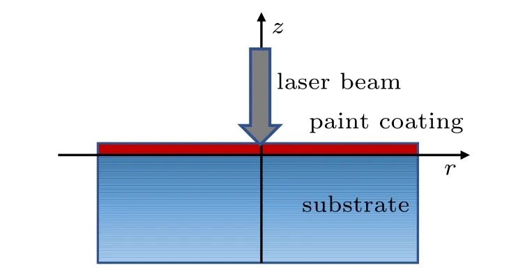
Fig.7. Coordinate diagram of paint layer–substrate structure.

whereT0is the initial temperature of the material, which is 293 K.Tfis the temperature of the laser action area.Tnis the temperature of the laser non-action area,his the convection heat transfer coefficient,σis Boltzmann constant andεis the emissivity of the material.
The energy density of Gaussian pulsed laser can be expressed as[14]

whereI0is the initial intensity of the incident laser,τis the pulse width, andr0is the laser spot radius. In the laser paint removal process, the incident laser pulse is used as the heat source, and the paint layer and substrate absorb a part of the energy. According to the law of light absorption by matter,the intensity of the light absorbed in each layer can be expressed as

HereIxis the intensity of the laser after transmittingxm underwater, andu(λ)is the attenuation coefficient of the beam.It is known that the attenuation coefficient of the 1064 nm laser in pure water is about 34.2.[15]
A two-dimensional finite element model in COMSOL multiphysics software was used to simulate the temperature distribution during the laser paint removal. The size of the paint layer was 1.2 mm×24 μm. However,because the temperature distribution of the substrate is approximately 3 μm deep on the surface,to reduce the calculation time,the size of the substrate was set to be 1.2 mm×5 μm. The Gaussian surface heat source was loaded onto the upper boundary surface to obtain the distribution of the temperature field in the material over time. The physical parameters of the paint layer and substrate are listed in Table 1.[16]
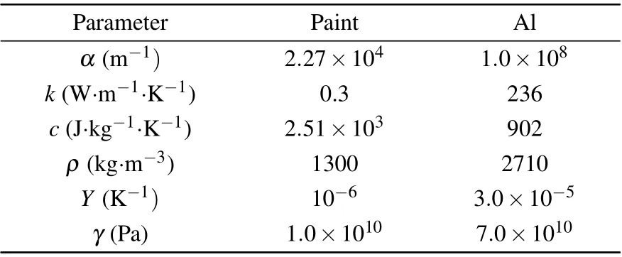
Table 1. Physical parameters of paint film and substrate.
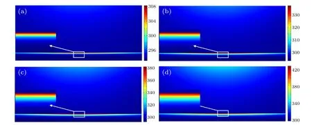
Fig.8. Temperature distribution of samples in air: (a)3 ns;(b)6 ns;(c)9 ns;(d)12 ns.

Fig.9. Temperature distribution of samples in water environment: (a)3 ns;(b)6 ns;(c)9 ns;(d)12 ns.
For the paint layer having a thickness of 24 μm in the experiment, it is evident from Figs. 2 and 3 that when the laser fluence was 0.49 J/cm2the paint layer was removed in both the water and air environments,and the substrate was not damaged. Therefore,under irradiation with a laser fluence of 0.49 J/cm2, based on the thermal deposition effect, the temperature distribution of the paint and substrate along the laser transmission direction with time was studied in this paper, as shown in Figs.8 and 9. However,because the temperature of the substrate is greater than that of the paint layer, the temperature change of the paint layer is not obvious in the figure,but it is evident from the temperature distribution of the aluminum substrate that the temperature in the center of the laser spot is the highest, and gradually decreases along the radial distribution with its temperature field conforming to a Gaussian distribution. As the laser irradiation time increased,the temperature of the paint layer and the substrate increased rapidly, and the temperature of the whole sample reached its highest value at the end of the laser pulse, and the temperature rise of the center of the target in the air is higher than in the water. This is because when there is a water layer on the target surface, the water due to its high heat flux and specific heat absorbs the excess heat of the sample and causes the energy deposited on the surface of the sample to diffuse rapidly.Therefore, the temperature of the paint layer and the metal substrate in the water was significantly lower than that in the air.

Fig.10. The temperature of the sample at the center of the laser beam radiation: (a)air,(b)water environment.
To show the variation in the sample temperature with depth more intuitively, Fig. 10 shows the distribution of the highest temperature (t= 12 ns at the end of pulse) of the laser beam radiation center at different depths when the laser fluence is 0.49 J/cm2. From the spatial distribution of temperature, it is evident that the temperature of the paint layer gradually decreases along the axial direction from the surface,but increase sharply to the highest temperature on the surface of the metal substrate, followed by a rapid drop and finally falling to room temperature in the range of 2–3 μm. Further,when the temperature exceeds the burning point or vaporization temperature of paint, it results in intense combustion or vaporization, and the vapor quickly condenses into droplets on the surface forming micro-nano particles of different sizes,as shown in Fig.4.[17]In this process,the carbon dioxide produced by the combination of C in the paint layer and oxygen in the air reduces the content of the remaining C, as shown in Fig. 6. Further, the substrate temperature changes significantly because the absorption coefficient of the metal substrate is much larger than that of the paint layer, while the specific heat of the metal substrate is much smaller than that of the paint layer, which causes the temperature of the metal substrate to increase sharply at the during the irradiation time.Owing to the strong absorption of light by free electrons in the metal, the light intensity rapidly decays, resulting in a rapid drop in temperature.[18]Thus,it is evident that,relative to the paint layer,the surface of the metal substrate is the place where the temperature is highest,and it is also the place most prone to thermal damage, which determines the removal effect of the paint layer. Based on whether the substrate is damaged or not, the damage is mainly caused by the melting of the substrate due to high temperature. After simulation calculation,the maximum threshold of paint removal under these conditions is 1.5 J/cm2.
3.2. Thermal stress
Considering the sample as an isotropic elastic body, the temperature of the sample increases because of the absorption of the laser energy, which causes thermal expansion of the sample,resulting in strain and stress. The thermodynamic parameters of the paint layer and substrate are quite different,specifically in terms of the absorption and thermal expansion coefficients.[19]Under irradiation with the same laser fluence,the temperature rise and thermal stress were quite different.For the removal of metal surface paint by laser, the force responsible for removal of the paint from the metal substrate is primarily the thermal stress produced by the interface between the paint and metal substrate. At the interface between the paint and substrate layers, the thermal stress of the paint bottom layer is opposite to that of the substrate surface, such that the cleaning force to remove the paint from the substrate surface should be the difference between these two thermal stresses.[16]Thus, the cleaning force can be obtained as follows:

The subscripts p and s represent the paint layer and the substrate, respectively,Yis the Young’s modulus,γis the linear thermal expansion coefficient, andσsandσpare the thermal stresses of the substrate and coating layer,respectively.
When the cleaning force between the metal substrate and paint is greater than the adhesion force(148 MPa),[20]the paint layer can be separated from the surface of the substrate. Here,it is necessary to consider whether the temperature of the substrate exceeds its melting point to determine whether the metal substrate will be ablated and damaged. Figure 11 shows the thermal stress distribution of the laser paint removal in air and water.

Fig.11. Thermal stress distribution of the sample at 12 ns: (a)air;(b)water environment.
Because the temperature of the aluminum surface is much higher than that of the paint layer,it is primarily dependent on the stress on the surface of the aluminum substrate in contact with the paint layer. As shown in Fig. 11, the stress of the substrate tends to spread at the center of the spot,showing an obvious stress gradient at the edge of the spot. When paint removal is carried out in air,the stress of the aluminum substrate reaches 400 MPa,much greater than the adhesion between the paint layer and the substrate, which causes the paint layer to crack and realize paint removal, as shown in Fig. 2(d). The removal range is about the whole spot diameter(1200 μm). In contrast, when removing paint in water, the maximum stress of the substrate is 140 MPa, which is less than the adhesion between the paint layer and the substrate. The thermal stress is not sufficient to separate the paint layer from the substrate.Therefore,it is necessary to analyze the effect of paint removal in water via other physical mechanisms.
3.3. Laser plasma effect
In air,under the irradiation of a high-intensity laser pulse,the high temperature effect of the metal substrate causes the adjacent paint film polymer to melt and vaporize rapidly, resulting in the generated vapor absorbing the laser energy violently. However, the continuous increase in temperature ionizes the paint and generates laser plasma,which,owing to the inverse bremsstrahlung effect,[21]hinders the propagation of laser energy to the target. The high temperature and pressure plasma radiates broad-spectrum light,continuously compresses the surrounding medium,and expands outward to form a laser-induced plasma shock wave, which causes significant damage to the paint and even the substrate. The force of the shock wave is closely related to the intensity of the incident laser,which can be described as

whereλis the wavelength of the incident laser andbis a constant related to the material, which is approximately 5.[22]When the laser fluence is 0.49 J/cm2, the peak stress is 3.48 MPa, which is far less than the adhesion between the paint layer and the substrate. Therefore, the removal of the paint layer in the air is primarily due to the energy deposition under laser irradiation, thus, the thermal stress plays a major role when the paint layer is removed from the air. Based on the criterion that the difference of thermal stress between paint layer and substrate is higher than the adhesion between them,the minimum threshold of paint removal in air is 0.17 J/cm2.Therefore,the range of paint removal in air is from 0.17 J/cm2to 1.5 J/cm2.
In contrast, when the laser irradiates the target in water,owing to the restriction of water, the expansion of plasma is limited, so the plasma shock wave is mainly concentrated in the center of the spot, and a large amount of laser energy is coupled in the plasma shock wave on the water–paint contact surface. Here, the shock wave pressure is significantly increased compared to that of air. The peak impact force of the laser pulse in water can be expressed as[23]

whereais the proportional coefficient of plasma heat energy to internal energy, taken as 0.1, andzAandzCare the acoustic impedances of paint and water, respectively. Here, the impedance of paintzAis 0.36×10⁶g/cm2·s,[24]impedance of substratezBis 1.5×10⁶g/cm2·s,[25]impedance of waterzCis 0.15×10⁶g/cm2·s,[25]laser fluence is 0.49 J/cm2,and peak impact force is 166 MPa. Therefore, when paint is removed in water, the paint is primarily sprayed by the plasma shock wave, as shown in Fig. 5(b). Moreover, the less oxygen in the water environment,leads to difficulties in causing ablation reactions,thus,the contents of carbon and oxygen are not significantly different from the original paint layer, as shown in Fig.6.
When the shock wave propagates in water,paint,and aluminum,it is reflected and transmitted at the both the interfaces of the paint–aluminum and water–paint because of the different impedances of the water,paint film,and substrate. The reflection and transmission coefficients can be obtained according to the continuous conditions and law of conservation of momentum.
The reflection coefficientRand transmission coefficientTof the contact surface between the paint layer and the substrate can be described as[26]
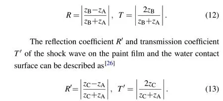
The plasma shock wave produced by the laser breakdown of water and paint is considered the incident wave, and is a compression wave. When the incident wave propagates to the interface between the paint film and substrate, reflection and transmission occur. However, because the impedance of the paint film is less than that of the substrate, the reflected and transmitted waves are still compression waves, and the transmitted wave increases compared to the incident wave. When the compression wave reflected to the paint film propagates to the water–paint interface, the greater impedance of the paint film than that of water, causes the reflected wave to change into a tensile wave. Further,when the tensile stress is greater than the tensile strength of the paint film,the paint film breaks,causing the high pressure plasma to spray outward and relieve pressure, and thus removing the paint film. Therefore,to prevent the substrate from being damaged when the paint is removed, the tensile stress reflected at the water–paint interface should be greater than the tensile strengthσpof the paint,while the compressive stress transmitted to the substrate should be less than the compressive strengthσsof the substrate,that is,

The range of the laser energy density for optimum paint removal can be obtained as follows:

The curves of the tensile stress, compressive stress and thermal stress of the paint caused by the laser plasma shock wave are shown in Fig.12,all of which increase with the laser fluence. Point A corresponds to the laser fluence for the tensile stress of the paint reaches the tensile strength (4 MPa),the laser fluence corresponding to point B is the breakdown threshold of water, and point C corresponds to the laser fluence for the compressive stress of the substrate reaches the compressive strength(276 MPa),[27]while point D is the minimum laser fluence to achieve thermal stress removal in water,which is greater than the compressive threshold of the substrate. Therefore,the maximum threshold of paint removal in water is 0.53 J/cm2. Because the theoretical energy density of just breaking paint is lower than the breakdown threshold of water, the minimum threshold of paint removal in water is 0.036 J/cm2. Therefore, the optimal energy density range of underwater paint removal should be 0.036–0.53 J/cm2.
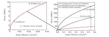
Fig.12. Tensile stress of paint layer,compressive stress and thermal stress of substrate under different laser fluence.
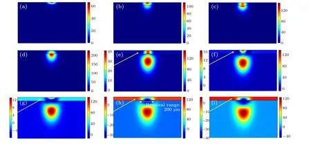
Fig.13. Propagation process of plasma shock wave in the sample: (a)6.8 ns;(b)12.3 ns;(c)16 ns;(d)21.4 ns;(e)32.9 ns;(f)34.2 ns;(g)34.6 ns;(h)37 ns;(i)38.1 ns.
Further, COMSOL multiphysics software was used to simulate the transmission of shock waves in materials and the process of stress generation. The size of the paint was 1.2 mm×24 μm, and the size of the substrate was 1.2 mm×1 mm. The peak pressure of the laser plasma shock wave was loaded on the upper boundary of the paint layer,and the side surface was set as a non-reflective boundary.Figure 13 shows the evolution process of the stress distribution changing with time during the transmission of the shock waves in the paint layer and aluminum substrate.It is evident from the pressure distribution diagram of the shock wave that the pressure in the center area of the laser spot is the largest during the downward transmission of the shock wave, and decreases in turn along the axial and radial directions.At first,the shock wave is coupled from the water to the surface of the paint layer(6.8 ns,Fig.13(a)),and then gradually propagated downward. Subsequently, it begins to propagate through the paint layer to the substrate (12.3 ns, Fig. 13(b)). When the shock wave propagates to the middle of the paint layer interface, its surface is spherical, and the shock wave propagating towards the substrate is more than twice as large as that of the paint layer(16 ns, Fig. 13(c)). At 21.4 ns, the shock wave propagating to the substrate reaches the maximum(Fig.13(d));thereafter,it starts to reflect at the interface between the paint layer and substrate(32.9 ns–34.2 ns, Figs.13(e)and 13(f)), and the reflected wave continues to reflect when propagating to the interface between the paint layer and water. Here, the stress propagating to the paint layer is the tensile stress (34.6 ns–38.1 ns, Figs.13(g)–13(i)). When the tensile stress is greater than the tensile strength of the paint layer (4 MPa), the paint layer will be sprayed and removed, and the removal range is only in the center of the spot,which is about 200 μm,far less than that in air. Compared with the substrate,the stress intensity in the paint layer in Figs.13(e)–13(i)is too small and the color change is not obvious;therefore,the stress distributions of the two layers of materials are shown separately. The color legend of the paint layer is represented on the left side of the figure, while the color legend of the substrate is on the right side.
4. Summary
In this study, the mechanism of paint removal in a water environment was studied. The research shows that in water,the stress coupled with the plasma shock wave causes the paint layer to break and be removed; while in air, laser ablation causes a phase change in the paint layer,and the removal is primarily due to thermal stress. The water absorbs the laser energy deposited by paint,therefore,the rising temperature of the sample is greatly reduced compared with that in air, and thus the ablation effect is reduced. However, compared with air,the plasma shock wave intensity in the water environment increase greatly,and the paint is broken and removed after being coupled into the paint. If the shock wave intensity is too high,the substrate will be damaged. To find the best laser parameters for underwater paint removal,the plasma shock wave pressure must be greater than the tensile strength of the paint and less than the compressive strength of the substrate,which will result in the energy density range for paint removal being obtained.
Acknowledgments
Project supported by the Joint Fund of the National Natural Science Foundation of China and the China Academy of Engineering Physics NSAF(No.U2030108),Sichuan Science and Technology Program(No.2021YFSY0027), and the National Natural Science Foundation of China(No.U2004162).
猜你喜欢
杂志排行
Chinese Physics B的其它文章
- Ergodic stationary distribution of a stochastic rumor propagation model with general incidence function
- Most probable transition paths in eutrophicated lake ecosystem under Gaussian white noise and periodic force
- Local sum uncertainty relations for angular momentum operators of bipartite permutation symmetric systems
- Quantum algorithm for neighborhood preserving embedding
- Vortex chains induced by anisotropic spin–orbit coupling and magnetic field in spin-2 Bose–Einstein condensates
- Short-wave infrared continuous-variable quantum key distribution over satellite-to-submarine channels
