High-brightness photo-injector with standing-wave buncher-based ballistic bunching scheme for inverse Compton scattering light source
2022-06-18JianXinWangKuiZhouPengLiDeXinXiaoLiJunShanXuMingShenYuLiuZhengZhou
Jian-Xin Wang · Kui Zhou · Peng Li · De-Xin Xiao · Li-Jun Shan ·Xu-Ming Shen · Yu Liu · Zheng Zhou
Abstract We report our recent progress in the design and simulation of a high-brightness S-band photo-injector with a ballistic bunching scheme aimed at driving an inverse Compton scattering (ICS) X-ray source. By adding a short standing-wave buncher between the RF gun and first booster in a conventional S-band photo-injector, electron bunches with a 500 pC charge can be compressed to the sub-picosecond level with very limited input RF power and an unchanged basic layout of the photo-injector. Beam dynamics analysis indicates that fine tuning of the focusing strength of the gun and linac solenoid can well balance additional focusing provided by the standing wave buncher and generate a well-compensated transverse emittance.Thorough bunching dynamics simulations with different operating conditions of the buncher show that a buncher with more cells and a moderate gradient is suitable for simultaneously obtaining a short bunch duration and low emittance. In a typical case of a 9-cell buncher with a 38 MV/m gradient, an ultrashort bunch duration of 0.5 ps(corresponding to a compression ratio of >5) and a low emittance of <1 mm·mrad can be readily obtained for a 500 pC electron pulse. This feasible ballistic bunching scheme will facilitate the implementation of an ultrashort pulse mode inverse Compton scattering X-ray source on most existing S-band photo-injectors.
Keywords Beam brightness · Ballistic bunching ·Emittance compensation · Compton scattering X-ray source
1 Introduction
In recent decades, inverse Compton scattering (ICS)light sources[1–3]have drawn increasing interest for their applicability in various scientific fields owing to their unique ability to produce bright quasi-monoenergetic ultrashort X-rays [4]. Moreover, scattered by relativistic electron bunches at hundreds of MeV, the incident laser with a wavelength of 800–1064 nm can be easily blueshifted to the γ-ray regime[5–7],which is beyond the reach of conventional free-electron lasers or synchrotron radiation facilities. Generally, a typical photo-injector is installed to drive an ICS source,and the performance of the X-ray source is mainly determined by the beam quality generated by the photo-injector. Taking the 180°collision between the laser and electron bunch as an example, the peak brightness Bxis proportional to the brightness of the electron beams, as described by [8]

where γ is the Lorentz factor, Q is the bunch charge, ∈n is the normalized emittance, and σzis the duration of the electron pulse. It can be deduced from Eq. (1) that maintaining a low emittance and short pulse duration is key to obtaining high-brightness X-ray pulses. Because the X-ray pulse duration is identical to that of the electron bunch in the 180°collision scenario,a compressed electron bunch is favored to generate ultrashort X-rays. Additionally, in the special design of a very compact ICS gamma ray source(VIGAS)project at Tsinghua University,the S-band photoinjector-generated electron bunches must be compressed before entering the X-band main accelerators to avoid an intolerable energy spread.
In a standard high-brightness photo-injector [9], the Sband, for example, electron bunches are generated and quickly accelerated to a few MeV in a high-gradient RF gun [10, 11]. A solenoid at the exit of the gun is used to focus the divergent electron beams, which is also referred to as the emittance compensation [12]. At the beam waist position,the main accelerators are placed to boost the beam energy and help ‘‘freeze’’ the emittance evolution [13].With the application of the emittance compensation scheme, the normalized emittance can be controlled to a 1 mm·mrad/ nC level [14, 15] on the premise of appropriate drive laser settings. Regarding the longitudinal aspect, owing to the lack of bunching cavities, the pulse duration of the electron bunch is almost identical to that of the drive laser, which is usually a few picoseconds (ps).
The most convenient method for obtaining ps- or subps- level ultrashort electron pulses and subsequent X-ray pulses is inserting a short section of the bunching cavities between the electron gun and main accelerator. This socalled ballistic bunching scheme [16] neither changes the basic layout nor adds complexity to the photo-injector, in contrast to the chicane compression or velocity bunching scheme, which uses a long accelerator as a buncher[17–21]. More importantly, the utilization of a chicane compressor also causes emittance growth owing to the space charge and coherent synchrotron radiation effects in the bend plane [22]. The first demonstration of ballistic bunching using a 42-cm-long standing-wave buncher achieved a compression ratio of 10 for high-charge electron beams, but at the cost of dramatic emittance degradation[23].In a previous study by Ding et al. [24],a 30-cm-long travelling-wave buncher was used to compress a 500 pC,10 ps electron beam by over 3.5 times, and the emittance was preserved by tuning the magnetic strength of the solenoid surrounding the first main booster. However,owing to the low acceleration efficiency, the total RF power fed to the buncher is up to approximately 20 MW,which brings pressure to the expensive RF power source.
In this study, we evaluate the feasibility of using a highly efficient standing-wave buncher to compress a highcharge electron beam while maintaining low transverse emittance. In Sect. 2, the beamline design of a modified photo-injector with a standing-wave buncher is introduced alongside the general beam dynamics analysis. The detailed bunching dynamics simulations are presented in Sect. 3. Finally, start-to-end simulations of the highbrightness photo-injector with a ballistic bunching scheme,from the RF gun to the interaction point, are presented in Sect. 4 with the aim of driving ultrashort pulse mode ICS facilities.
2 Beamline design and general beam dynamics
The high-brightness photo-injector with the ballistic bunching scheme proposed here is modified from the common S-band photo-injector used in other ICS sources,such as the Tsinghua Thomson scattering X-ray source [2]and Xi’an gamma-ray source [15]. Electron beams were generated and quickly accelerated to approximately 4.7 MeV in a high-gradient BNL-type S-band RF photo gun.At the gun’s exit, an approximately 20-cm-long solenoid was used for the emittance compensation process. A 3 m long SLAC-type constant impendence travelling-wave acceleration tube located 1.5 m downstream of the cathode boosts the beam energy to the relativistic regime. The difference is the insertion of a multicell S-band standingwave buncher for beam compression and an extra solenoid(denoted as a linac solenoid) surrounding the first 1/3rd part of the first accelerator for beam envelope control.The basic layout of the photo-injector and the electric and magnetic field distributions is shown in Fig. 1.
The simulation studies began with a normal case of a photo-injector without a buncher. A typical high charge of 500 pC was chosen, which is the standard operating point to drive an ICS or FEL facility. After optimization, a laser pulse of length 10 ps (flat-top distribution) and radius 0.9 mm (uniform distribution) was set to produce a 500 pC bunch charge. The detailed parameters of the normal case of photo-injector are listed in Table 1. With a suitable focusing strength of the gun solenoid, a beam waist was formed at the entrance of the first linac(marked as linac-1),and the transverse emittance was fully compensated to 0.6 mm·mrad. Theoretically, this match condition is a balance between the space charge defocusing and RF kick at the entrance of linac-1, and the matched beam size can be estimated by [13]:

where mec2=0.511 MeV is the rest energy of an electron,Elinacis the acceleration of the linac peak, I is the beam current, and IA=17 kA is the Alfven current. Substituting Elinac=20 MV/m,I =50 A, and γ=10 into Eq.2 gives a matched beam size σmatch of 0.31 mm,which agrees quite well with the optimized 0.35 mm in the simulation.
In the absence of bunching cavities, the electron bunch length increases slowly in the drift space between the gun and linac because of the positive energy chirp (the bunchhead has a higher energy) imprinted by space-charge forces.After entering the accelerator at the 0°injection phase(maximum energy gain), the bunch length was maintained at an rms level of approximately 3 ps as the beam energy was boosted to the relativistic regime, and the particle velocity difference was negligible. Based on this, the final bunch length at the exit of the normal photo-injector is mainly determined by the pulse duration of the drive laser.The evolving curves of the transverse emittance,beam size,and pulse duration are shown in Fig. 2 (in carmine color).

Fig. 1 (Color online) Basic layout of photo-injector (top)and field distribution (bottom)

Table 1 Parameters of the normal photo-injector case
Next, a standing-wave buncher was added to the photoinjector dynamics simulations. The applied buncher comprised five cells and operated in the π mode. The entire length of the buncher was approximately 36 cm, with a 5-cm-long entrance and exit ports. The electromagnetic simulations show that the gradient can reach 36 MV/m with 2.1 MW RF power fed into the buncher, as shown in Fig. 3. Using identical photo-injector parameters as those listed in Table 1 and the buncher working at 38 MV/m and-100°phase, a beam waist is formed at approximately 20 cm ahead of the linac-1, and the transverse emittance is deteriorated to more than 2 mm·mrad. This mismatched beam envelope was caused by the RF focusing effect in the standing-wave buncher, as shown in Fig. 2a, b. Moreover,the transverse beam size quickly expanded in the accelerator section without the linac solenoid. In the longitudinal aspect, a compression ratio R of 2.2 is obtained, which is significantly different from that obtained from the overcompression case. Here, R is defined as
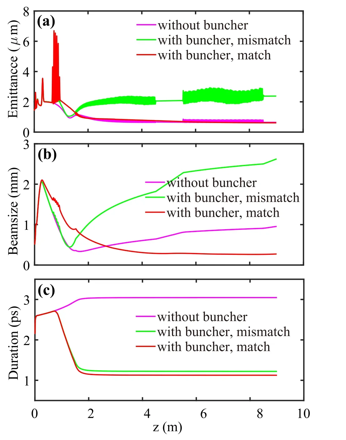
Fig.2 (Color online)Beam dynamics including a emittance,b transverse beam size, and c bunch duration in three different cases: 1)without buncher (in carmine color);2)with buncher and mismatched solenoid focusing strength (in green color); 3)with buncher and matched solenoid focusing (in red color)
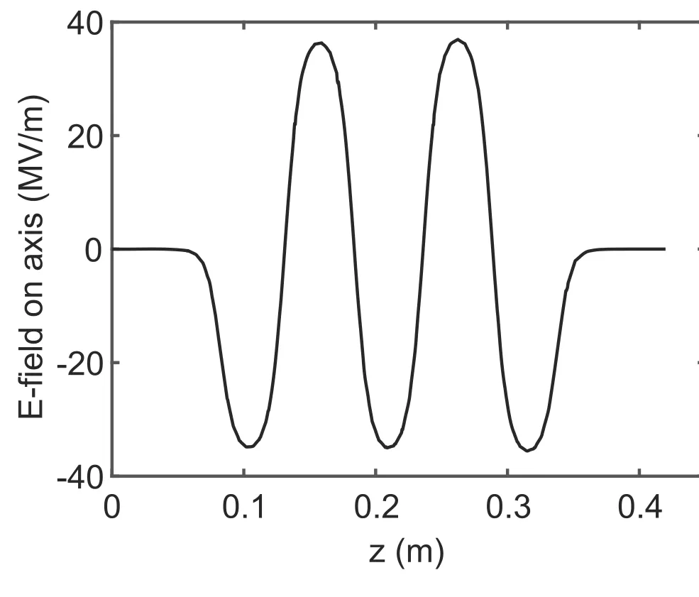
Fig. 3 Electrical field of buncher with 2.1 MW power input
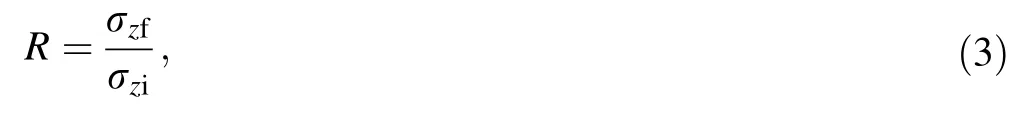
where σzfis the final bunch length at the exit of the photoinjector,and σziis the initial bunch length at the entrance of the buncher.
Because the buncher can provide extra RF focusing, a straightforward solution is to reduce the magnetic strength of the gun solenoid. Additionally, the focusing strength of the linac solenoid should be finely tuned to control the beam envelope in the accelerator section. Astra [25] simulation shows that when the strength of the gun solenoid is reduced to 2000 Gs and of linac solenoid to 700 Gs (other parameters are identical to the ‘‘mismatch case’’), electron beams are matched into linac-1, and the emittance oscillation is quickly damped to 0.6 mm·mrad level. In this case, both the beam decelerating and alternating RF focusing/defocusing situations occur,and Eq.2 is no longer applicable. Moreover, it is difficult to obtain an analytical solution. The longitudinal compression ratio obtained in this case is higher (R of 2.4) than that obtained in the matched case. This phenomenon is due to the lower space charge densities with larger transverse dimensions, which subsequently induce smaller positive energy chirp.
From this preliminary beam dynamic simulation, it is observed that a low transverse emittance can still be obtained in a standing-wave buncher-based ballistic bunching scheme with a very limited RF power. The key step is to balance the solenoid focusing,extra RF focusing,and space-charge forces.Previous work has shown that the transverse emittance can be fully compensated with a maximum compression ratio of 4 using a traveling-wave buncher. Thus, it is significant to explore the ultimate bunch compression with a standing-wave buncher while maintaining a low transverse emittance. In the following sections, detailed numerical simulations are performed to evaluate the effects of different factors on the ballistic bunching scheme with emittance compensation,such as the buncher voltage, buncher gradient, and working phase.
3 Bunching dynamics simulations
This part of the numerical simulations was conducted to examine the ultimate longitudinal compression without excessive emittance spoiling. Here, the upper limit of the normalized transverse emittance εn was set to 1 mm·mrad,corresponding to a geometric emittance εg of 5 nm·rad with γ = 200. For common ICS experiments, the beam divergence σx′produced by strong focusing quadrupoles is estimated to be of the order of 1 mrad. Thus, the RMS beam waist at the interaction point can reach σx=εg/σx′~5μm , which is sufficient to produce a micron-level X-ray source size via collision with highpower lasers focused to a few microns.
In the following simulations, the working parameters of the drive laser, RF gun, linac-1, and linac-2 were fixed, as listed in Table 1.All simulations were carried out using the ASTRA code, including 105macro-particles.
3.1 Five-cell buncher case
Because the drift length between the buncher and linac-1 is fixed,the compression ratio is determined by the buncher gradient and the injection phase. More specifically, for a fixed buncher gradient (Eb) or energy modulation amplitude, lowering the injection phase (φ) to just the deceleration phase (<-90°) leads to a higher compression ratio.For a fixed injection phase, a higher buncher gradient will give a larger energy chirp, and thus deeper bunching.Therefore, based on the simulation described in Sect. 2,detailed longitudinal compression processes are conducted by varying the buncher injection phases.At each phase,the focusing strengths of the gun and linac solenoids were carefully optimized to achieve the lowest transverse emittance at the photo-injector exit. Similar procedures are repeated using this 5-cell buncher with gradients of 38 MV/m, 43 MV/m, 47.5 MV/m, and 52.5 MV/m, respectively.The scanning results for the optimized emittance εn with different buncher gradients and phases are illustrated in Fig. 4. For each combination of (Eb, φ), the strengths of the gun and linac solenoids are scanned simultaneously,which also affects the final bunch length. Therefore, using the final bunch length as the x-axis in Fig. 4 instead of φ is more reasonable.
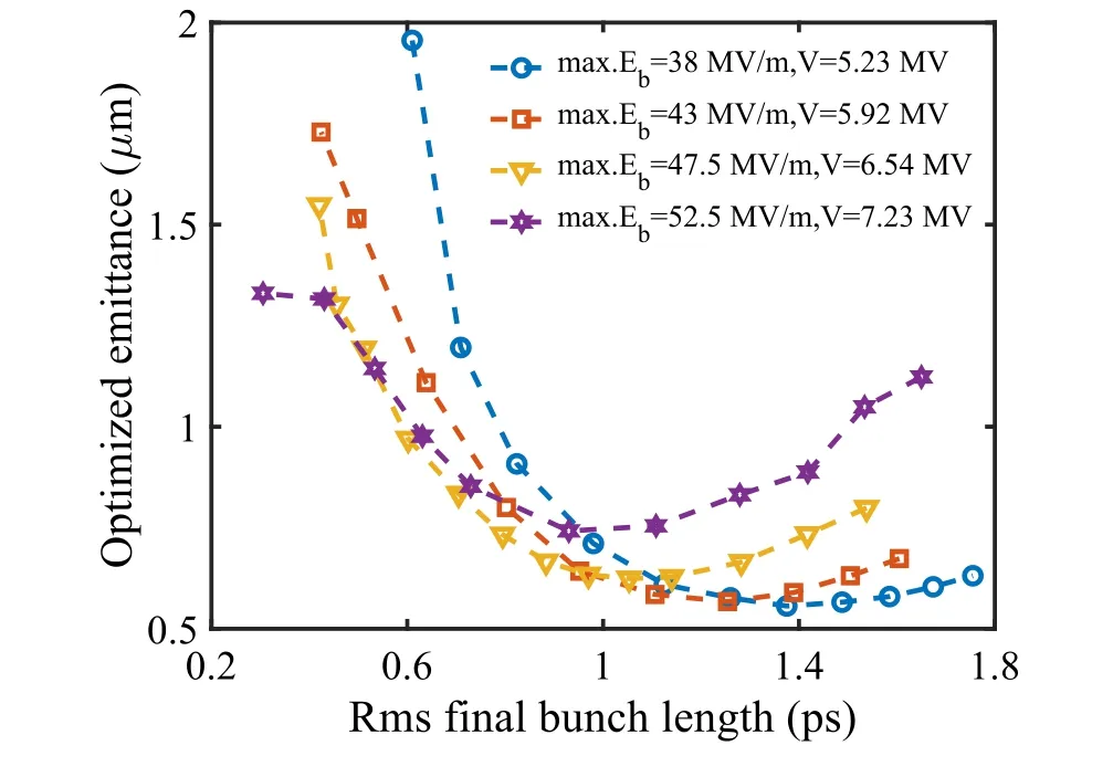
Fig. 4 (Color online) Optimized normalized transverse emittance versus RMS final bunch durations under different buncher gradient conditions
A clear trend observed in Fig. 4 is that for each buncher gradient,there is a best compression ratio point,where the transverse emittance is well preserved. Away from these points,compression ratios that are too low or too high will lead to emittance growth, especially in dramatic bunching cases wherein emittance compensation is more difficult with increased beam current. Additionally, the final bunch durations corresponding to the best compression ratio points become shorter with increasing buncher gradient because a larger energy chirp is helpful for further compression. Although a high gradient is favored for short bunches, a gradient that is too high will jeopardize emittance compensation. This conclusion can be reached by comparing the optimized emittance results between 47.5 MV/m and 52.5 MV/m, where larger emittance values are obtained in the latter case with compression ratios up to 6.In this sense, 47.5 MV/m is the most suitable gradient for this five-cell buncher,and transverse emittance can be well compensated with a maximum compression factor of 4.5,corresponding to a final bunch length of RMS 0.6 ps.
The emittance evolution in the low-R and high-R bunching processes can provide insight into the emittance compensation with a ballistic bunching scheme. In Fig. 5,we present the transverse emittance and beam size envelope along the beamline at three different injection phases(-85°,-95°and-100°)and same gradient of 52.5 MV/m,corresponding to a R of 1.64,2.9,and 6.23,respectively.It can be observed that increasing the beam current via bunch compression causes an increased emittance oscillation frequency and forms a beam waist ahead of linac-1(see the high-R case in Fig.5,marked by the solid green line).This trend is opposite in the low-R case,where the beam waist is formed inside linac-1, and both the beam size and emittance increase almost linearly after the beam waist location.This phenomenon is similar to that in the mismatched beam envelope case presented in Fig. 2, but with the optimized focusing strength of both solenoids.
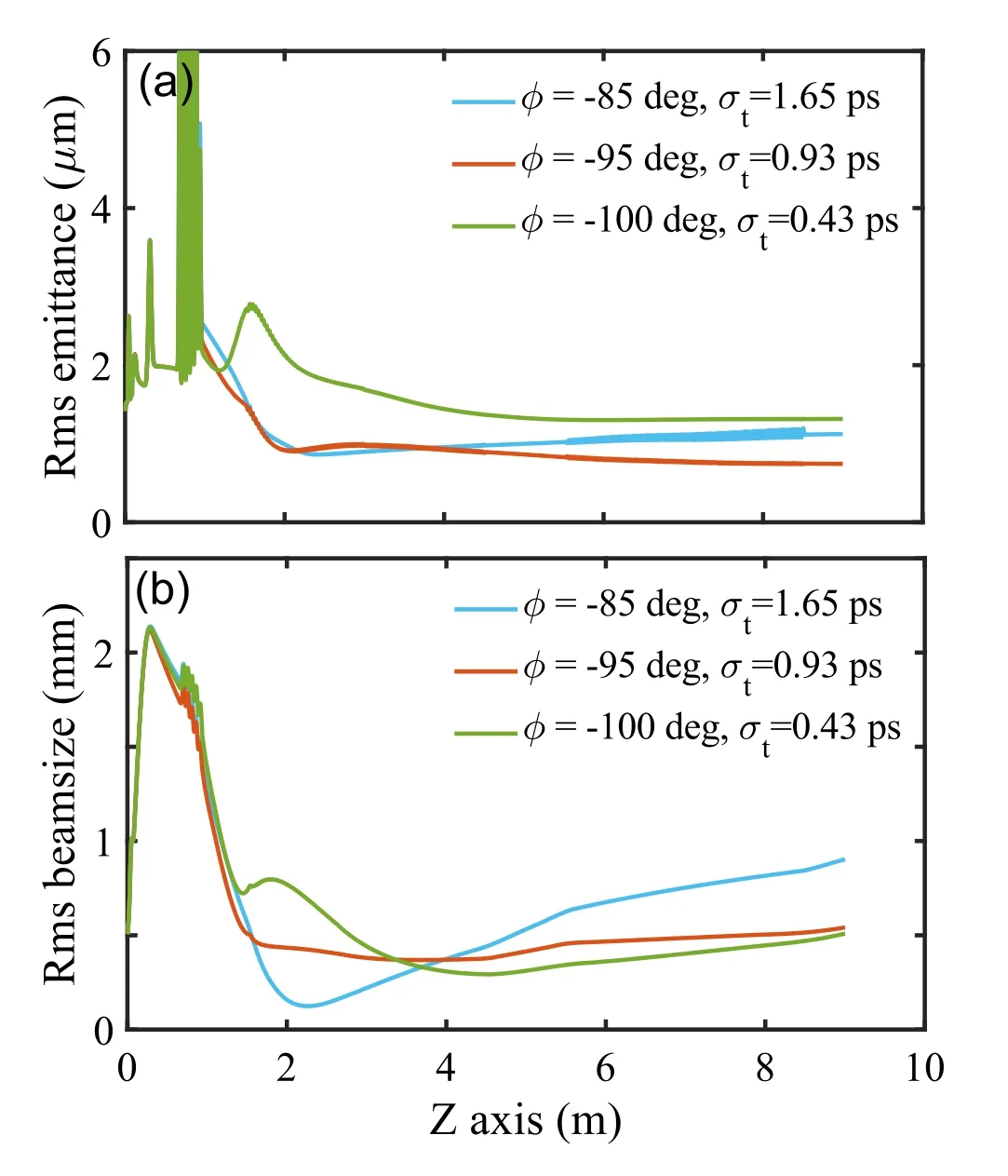
Fig. 5 (Color online) a Optimized emittance, and b beam size in different bunching cases: low-R bunching (in solid blue line), best compression ratio bunching(in solid orange line),and high-R bunching (in green blue line)
Here, we emphasize that all the optimized transverse emittance results were obtained in normal compression cases. Emittance compensation in the over compression scenario was also observed.Based on the simulations under the Eb =52.5 MV/m condition in Fig.4,the buncher phase φ is set to-102°and a longer bunch length(σt =0.325 ps)is obtained than that of the 101°phase (σt = 0.3 ps), thus indicating the arising of over compression.In this case,the optimized transverse emittance has a notable growth from approximately 1 mm·mrad to 2.36 mm·mrad, see Fig. 6(a). Additionally, the longitudinal phase space at several positions, including the entrance of the buncher, entrance of linac-1,first few cells,and exit of linac-1,is displayed in Fig.6(b).The blue,black,and red dots in Fig.6b represent the bunch tail,bunch center,and bunch head,respectively.Evidence of the crossover between different longitudinal slices can be clearly observed,especially in the bunch head and bunch center, which is usually referred to as wavebreaking. Moreover, nonlinearity in the ballistic bunching process was evident.

Fig. 6 (Color online) a Optimized emittance versus different final bunch durations at Eb = 52.5 MV/m. The black dashed line represents the normal compression cases, whereas the red dashed line represents the over compression case; b evolution of the longitudinal phase space from the entrance of the buncher to the exit of linac-1

Fig. 7 (Color online) Optimized emittance versus different final bunch durations at Eb = 52.5 MV/m. The black dashed line represents the normal compression cases, whereas the red dashed line represents the over compression case. The inset shows the longitudinal phase space of the over compression case
Moreover, the optimized gun and linac solenoids focusing strengths were recorded at each working point of(Eb, φ), as shown in Fig. 7. In our simulations, the gun solenoid is scanned from 0.19 T to 0.21 T at a step size of 10 Gauss, whereas the linac solenoid from 0 to 0.15 T at a step size of 100 Gauss. At a fixed buncher gradient, the variation in the optimized magnetic strength of the gun solenoid is not obvious when the buncher injection phase is changed, which is maintained within a small range of 50 Gauss.A general trend is that a weaker focusing of the gun solenoid is required with an increased buncher gradient,as stronger RF focusing is provided in this case.For the linac solenoid, the optimized magnetic strength increases as the final bunch duration decreases with a lower injection phase φ. Compared with the gun solenoid, the large-scale variance of the optimized linac solenoid strength can exceed 500 Gauss (see Fig. 7b), thus causing difficulties in the optimization of the linac solenoid strength.This is why the linac solenoid is scanned with a larger step size than the gun solenoid. Moreover, stronger focusing of the linac solenoid is required with an increased buncher gradient,which is opposite to that of the gun solenoid. This is because a higher buncher gradient causes weaker focusing of the gun solenoid combined with stronger RF focusing resulting in a larger divergence and subsequently expanded beam envelope in the booster, which is compensated by focusing provided by the linac solenoid to damp the emittance oscillations to obtain a low emittance.
3.2 Buncher with more cells
Because a higher amplitude of the energy modulation by the RF buncher is needed to obtain short electron bunches,while a buncher gradient that is too high will cause difficulties to emittance compensation, a buncher consisting of more cells and working at moderate gradient should fit the ballistic bunching scheme more than the 5-cell buncher.To validate this hypothesis, the same simulation procedure as the 5-cell buncher was repeated using a 7-cell buncher and 9-cell buncher. The results are shown in Fig. 8.
As observed, the general trend of the optimized emittance versus the final bunch durations using the 7-cell and 9-cell bunchers is similar to that of the 5-cell buncher.At a fixed buncher gradient, the lowest emittance was obtained when the bunch length was compressed to approximately 1 ps.In the 7-cell buncher case,the transverse emittance can be well compensated with a compression ratio of 4.5,under both 38 MV/m and 47.5 MV/m gradient conditions. This compression ratio is improved to 5.3 using a 9-cell buncher at a 38 MV/m gradient, as shown in Fig. 8.
3.3 Discussions
3.3.1 Choice of buncher voltage

Fig. 8 (Color online) Optimized emittance versus different final bunch durations using 7-cell and 9-cell bunchers
A clear conclusion can be drawn from the multi-cell buncher simulations that a deeper energy modulation or buncher voltage is required to obtain shorter bunches with low emittance. In typical applications, such as hybrid accelerating structures, including S- and X-band accelerators,a compression factor larger than 4 is desired.Different combinations of the buncher cell (Ncell) and gradient are summarized in Table 2, in which the transverse emittance are optimized up to 1 mm·mrad and the bunch duration is compressed to approximately rms 0.6 ps, responding to a compression ratio of 4.5. It can be easily observed that a buncher voltage of at least 7 MV is needed to obtain a compression factor of 4.5 with well compensated emittance. Moreover, further compression of the electron buncher to significantly less than 0.6 ps,a buncher voltage>9 MV is required, which is satisfied in the case of the 9-cell buncher with a 38 MV/m gradient.
3.3.2 Choice of buncher gradient
In addition to the overall energy modulation introduced by the buncher, the buncher gradient should be carefully considered. The choice of the buncher gradient is related not only to the beam bunching dynamics but also to the RF power input. For a specified energy modulation, a longer RF buncher with a lower gradient needs lower RF power,because the energy modulation amplitude scales with Eb×Lb, whereas the RF power required scales with E2b×Lb.
Here, the discussion of the optimal buncher gradient is based on the precondition of an approximately equal energy modulation amplitude or buncher voltage. In the first case of near 9 MV buncher voltage, using a 9-cell buncher working on a 38 MV/m gradient can obtain a lower emittance at each compression ratio working point than the 7-cell buncher working on a 47.5 MV/m gradient,as indicated by the red solid line and blue solid line in Fig. 8. A different trend is observed for a near 7 MV buncher voltage, where a 9-cell buncher working on a 30 MV/m gradient has a larger transverse emittance in the sub-ps regime than the 7-cell buncher working on a 38 MV/m gradient, as shown by the green dashed line and black dashed line in Fig.8.Therefore,a moderate buncher gradient of 38 MV/m is preferred over the other two in oursimulations. In the case of a 9-cell buncher with a 38 MV/m gradient, the total RF power is estimated to be only 4.2 MW, thus indicating a fourfold to fivefold reduction in the input RF power than a travelling-wave buncher.
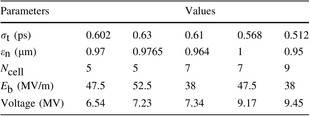
Table 2 Examples of short bunches with well compensated emittance
4 Start-to-end simulations of a bright photoinjector for ICS
In this section, an example of a bright photo-injector with a ballistic bunching scheme that is supposed to drive an ICS facility is presented. Based on the bunching dynamics simulation described in the previous section, the 9-cell buncher working on a 38 MV/m gradient was chosen to compress the electron bunches to the sub-ps regime. In addition to the accelerating section, the beam dynamics in the matching section should also be considered. This matching section is typically composed of multiple quadrupole magnets and is used to obtain the micron-scale transverse beam size at the interaction point. The main concern of beam dynamics in the matching section is the emittance growth during the beam focusing and defocusing processes,which leads to an expanded beam focal spot size at the interaction point. Because the emittance growth in the matching section is always caused by an improper transverse phase space as well as a large energy spread at the entrance of the matching section, start-to-end simulations of this bright photo-injector were carried out.
In this example, the 9-cell buncher is used with a 38 MV/m gradient and -97°phase to compress the final bunch length to approximately 0.5 ps. According to our former simulations, an emittance of 0.95 mm·mrad is obtained when the gun solenoid is set to 2010 Gs and the linac solenoid is set to 1500 Gs. However, the relatively large beam size (rms = 1 mm) at the entrance of the matching section causes notable emittance growth, which limits the generation of micron-scale beam focal spots. In this case, the solenoids were optimized to balance the emittance and beam size at the exit of the accelerator.Finally,an emittance of 0.99 mm.mrad and an rms of 0.68 mm beam size were obtained with the gun solenoid set to 2020 Gs and the linac solenoid set to 1100 Gs. The simulation results, including the energy gain, energy spread,and bunch duration,are shown in Fig.9,while the detailed beam parameters are listed in Table 3.
When the Twiss parameters β and α are known, we begin the beam optics design of the matching section.Matching magnets are composed of four equidistantly placed quadrupoles, commonly referred to as quadruplets.Here, matching the β function is realized by tuning the focusing/defocusing strength of the four quadrupoles, with the help of the beam optics code MAD [26]. After optimization,a beam focal spot is formed 1.7 m downstream of the entrance of the matching section, where minimum β*and α=0 are achieved on both the x and y planes, simultaneously,as shown in Fig. 10. The beam waist dimension at the interaction point can then be estimated using the following formula:

The optimized quadrupole focusing strength and β*are listed in Table 4. Here, the quadrupole coefficient QK is equal to G/Bρ, where G is the quadrupole field gradient,and Bρ is the magnetic rigidity. Assuming that negligible transverse emittance is introduced by the quadruplet, a beam waist of 8.7 μ m can be readily obtained according to Eq. 3.
In the beam optics simulations, the space charge forces and energy spread were not considered. In the last step,considering the optimized layout of the matching section in the ASTRA code, particle kinetic simulations are conducted to validate the beam optics design outcomes. Figure 11 shows the transverse beam size and emittance evolutions in the final matching section.It can be observed that a beam waist is generated 1.7 m behind the entrance of the matching section, which agrees well with the MAD outputs. The profile of the beam waist illustrated in Fig.11a shows a Gaussian distribution,with a beam size of 7.8 μm and 8.8 μm on the x and y planes, respectively.Moreover,it is interesting to find that εxdrops slightly from 0.99 mm·mrad to 0.96 mm·mrad, instead of undergoing emittance growth.
Overall, the beam dynamics simulation using ASTRA double-checks the effectiveness of the beam optics design.These start-to-end simulations verify the feasibility of this photo-injector to drive an ICS facility because a higher beam brightness rather than a standard photo-injector can be provided via a ballistic bunching scheme based on a short-section standing-wave buncher and limited RF input.
5 Summary

Fig.9 (Color online)Optimized beam parameters at the exit of the accelerating section:a transverse emittance and beam size,b energy spread,c energy gain, and d bunch length

Table 3 Beam parameters at the exit of the accelerator

Table 4 Parameters at the matching section
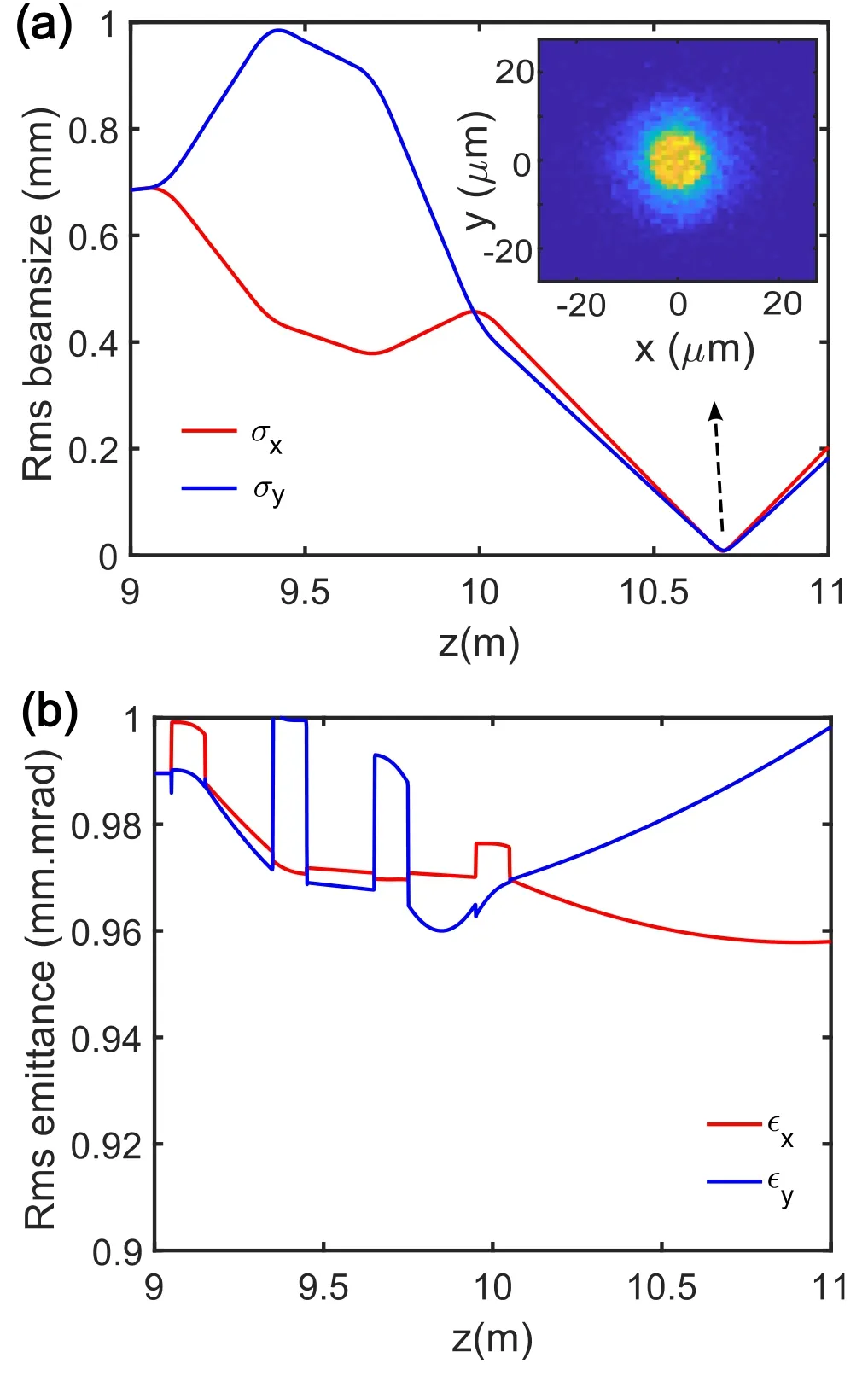
Fig.11 (Color online)a Transverse beam size,and b emittance in the matching section simulated by ASTRA. The inset shows the beam profile at the interaction point
In this study, a new attempt was made to improve the brightness of a conventional S-band photo-injector via a ballistic bunching scheme based on a short,highly efficient standing-wave buncher. General beam dynamics simulations show that electron beams experience additional RF focusing in the standing-wave buncher. By loosing the focusing of the gun solenoid while adding the focusing of the linac solenoid to control the beam envelope, the transverse emittance can be effectively compensated with a reasonable compression ratio. Beam bunching simulations with a multicell standing-wave buncher revealed an interesting fact that for a fixed buncher gradient, the best emittance compensation results occur at a specified compression ratio, and the optimized emittance will increase when the compression ratio is too large or too small.This is because a deeper bunch compression leads to a higher beam current and subsequently increases the emittance oscillation frequency. This could not be compensated by optimizing the solenoid focusing strength without changing the basic layout of the photo-injector, especially the location of the first booster. Thorough bunching dynamics simulations using different numbers of coupling cells and buncher gradients indicated that a buncher with more cells and a moderate gradient helps obtain a short bunch duration and low transverse emittance simultaneously. In our simulations, an electron bunch with a duration of rms 0.5 ps and an emittance of 0.95 mm.mrad can be readily obtained using a 9-cell buncher with 38 MV/m gradient.Furthermore, the buncher will require an RF power<5MW, which is only a quarter of that required by a travelling-wave buncher. In this situation, the RF gun,buncher, and first linac can share a 50 MW klystron.Finally, start-to-end simulations of a photo-injector with a 9-cell standing-wave buncher are conducted, where the final bunch duration is compressed to 0.52 ps and the focal beam size at the interaction point is focused to <10 μm using a matching quadruplet. In summary, this study verifies the feasibility of adding a short standing-wave buncher to meet the requirements of the sub-picosecond ultrashort electron bunches while maintaining the transverse emittance. Combining the merits of the very limited RF power and maintaining the basic layout of a typical photo-injector, this standing-wave buncher-based ballistic bunching scheme should provide a feasible solution for ultrashort pulse mode ICS facilities.
杂志排行

Nuclear Science and Techniques的其它文章
- Development of a low-background neutron detector array
- Dication-accelerated anion transport inside micropores for the rapid decontamination of pertechnetate
- Iterative Bayesian Monte Carlo for nuclear data evaluation
- Sparing lung tissue with virtual block method in VMAT planning for locally advanced non-small cell lung cancer
- Decomposition of oil cleaning agents from nuclear power plants by supercritical water oxidation
- Signal modeling and impulse response shaping for semiconductor detectors