The scaling laws of cabin structures subjected to internal blast loading: Experimental and numerical studies
2022-05-24XinbenRenZhixinHungYongboJingZihoChenXiofeiCoTinZhoYingLi
Xin-ben Ren , Zhi-xin Hung , Yong-bo Jing , Zi-ho Chen , Xio-fei Co ,Tin Zho ,*, Ying Li ,*
aBeijing Key Laboratory of Lightweight Multi-functional Composite Materials and Structures,Institute of Advanced Structure Technology,Beijing Institute of Technology, Beijing,100081, China
bState Key Laboratory of Explosion Science and Technology, Beijing Institute of Technology, Beijing,100081, China
Keywords:Internal blast Cabin structure Scaling law Experimental study Numerical simulation
ABSTRACT This paper presents a combination of experimental and numerical investigations on the dynamic response of scaling cabin structures under internal blast loading.The purpose of this study is to modify the similar relationship between the scaled-down model and the prototype of the cabin structures under internal blast loading.According to the Hopkinson’s scaling law,three sets of cabin structure models with different scaling factors combined with different explosive masses were designed for the experimental study.The dynamic deformation process of the models was recorded by a three-dimensional digital imaging correlation (DIC) method and a 3D scanning technology was used to reconstruct the deformation modes of the specimen.In addition,a finite element model was developed for the modification of the scaling law.The experimental results showed that the final deflection-to-thickness ratio was increased with the increase of the model size despite of the similar trend of their deformation processes.The reason for this inconsistency was discussed based on the traditional scaling law and a modified formula considering of the effects of size and strain-rate was provided.
1.Introduction
With the development of strike precision and charge volume,anti-ship missiles are becoming one of the most significant threats for large naval vessels.However, blast loading, especially from internal explosion, can cause significant damage to the target structures.Therefore, greater emphasis has been placed on enhanced protection of military structures [1,2].Therefore, research on dynamic response of cabin structures under internal blast loading would not only facilitate the blast resistance design of the cabin structures,but also improve the vitality and combat effectiveness of naval vessels in the increasingly threatening explosive circumstance.
There are obvious differences between confined and free-field blast.For the former, structures are subjected to loading from multiple shock waves due to the multiple reflection of the shock waves in a confined field, which finally makes the peak pressure obviously higher than that in the free field [3,4].In addition, the high-temperature gas cannot be promptly released in a confined blast condition,which results in a quasi-static pressure lasting for a relatively long time [5,6].Liang [7] investigated the dynamic response of metallic corrugated core sandwich panels under blast loading, and carried out the optimum design of its antiknock performance.Feldgun et al.[8] integrated thermodynamic rules with Jones-Wilkins-Lee (JWL) equations and proposed a formula for predicting quasi-static pressure which fits well with the test data.Therefore, the dynamic response of marine structures, e.g.cabins,under internal blast loading have received more and more attention in recent years.Burman et al.[9]studied the deformation and failure processes of compartments subjected to internal blast loading, which serves to quantitatively and qualitatively identify the dynamic deformation and critical failure modes of the welded steel compartments under internally explosively loaded.Zheng et al.[10] explored the deformation modes of the stiffened plate under confined blast loading through experiments and numerical simulations, and analyzed the influence of the stiffeners and vent size on the structural deformation.Li et al.[11] analyzed the distribution characteristics of the internal blast loading on liquid cabin plates and obtained their typical deformation modes.Through a combination of experiments and numerical simulations, Yao et al.[12] investigated the dynamic response of steel boxes under internal blast loading, concluded six failure modes of the structure.Zhao et al.[13] investigated the dynamic response of stiffened plates under confined blast loading and provided a prediction formula for calculating the dimensionless deflection of stiffened plates.Kong et al.[14]studied the damage features of a multi-layer protective structure under the synergistic effect of blast and fragment loadings.The developed model was validated by experimental results and showed a qualified performance on predicting the response of a full scale structure under of the attack of anti-ship weapons.
In order to characterize the actual behavior of structures under explosion loading, it is, in theory, necessary to conduct full-scale explosion tests.However, these tests are rather limited due to the security constraints and high costs in their required resources.To represent the physical phenomenon of full-scale prototype, the scaled-down model experiments are highly desirable as the alternative, owing to their advantages of simple operation and high repeatability.Duffey et al.[15]validated the scaling laws for punchimpact-loaded structures, indicates the deflections of full-scale prototype is larger than half-scale model, and the deviation is generally within ten percent.Oshrio et al.[16]indicates that it is not possible to use a scaled model to predict the prototype behavior,but this problem is overcome by changing the impact velocity so that the model behaves exactly as the prototype.Neuberger et al.[17-19]studied the scaling law of circular plates under spherical air blast and buried blast explosions.Through various explosive load tests, Snyman [20] investigated the geometric similarity scale of steel plates, indicates the importance of material properties when attempting to demonstrate similarity in the midpoint deflection.Yao et al.[21] explored the problem of scaling in the deformation process of steel box structures subjected to internal blast loading through experimental and numerical investigations, and the deflection correction formula was given.
Based on the literature study, it can be seen that extensive research has been performed regarding the load characterization and structural response under internal blast loading.Regarding the investigations on the scaling laws, most researches are limited in the free-field blast.Therefore,the investigations on the scaling laws of cabin structures subjected to internal blast loading are still rare.
In this study,the dynamic response of cabin structures designed with different scaling factors combined with different explosive masses under internal blast loading were assessed experimentally and numerically.The characteristics of deformation modes, deformation processes and pressure evolution inside the cabins were analyzed.The reasons for the differences of the final deflection-tothickness ratio of different cabin configurations were discussed.Based on the results of experiments and numerical simulation,the scaling law for cabin structure was modified considering the size and strain-rate effects.
2.Experimental studies
With respect to shock wave scaling, the most commonly used method is Hopkinson’s scaling law [22,23].This law shows that if the explosive mass (same type) and distance were designed according to the scaling law, the shock waves generated by the explosion should be similar.The relevant scaling variables and their relationship are listed in Table 1.The scaling factor is denoted as β.The superscriptsandrepresent the prototype and scaled-down model, respectively.
2.1.Experimental setup
The ship cabin is basically a rectangular steel box.However, in the practical condition, cabins are connected to each other inside the ship.Therefore,the boundary conditions of the cabin structures are neither fixed nor simply supported.An offset side with a length of 1/5 of the plate width is considered as a reasonable boundary condition for the study on the dynamic response of steel box structures under internal blast loading [21].Therefore,this setting was directly adopted for the design of the cabin structure model in this paper, as illustrated in shown in Fig.1(a).A circular hole was pre-manufactured in the center of top plate for the purpose of placing the explosive.To provide a comprehensive study on the similar relationship between the scaled-down model and the prototype of the cabin structures under internal blast loading, three types of cabin specimens with different sizes,denoted as CS-I,CSII and CS-III, were designed (see Fig.1(b)) and their geometric parameters are listed in Table 2.The model CS-III with the largest size is regarded as the prototype,thus the scale-down factors for model CS-I,CS-II and CS-III are 2,1.33 and 1, respectively.The material used for the cabin structure model is Q235B Steel.The corresponding mechanical properties, as shown in Table 3, were calibrated in our previous work[11].
The design of the explosion tests is demonstrated in Table 4.Pentaerythritol tetranitrate (PETN) is utilized as the explosive in this research.Three different explosive masses were assigned for each type of the cabin specimen, which finally resulted in 9 experimental cases in total.Spherical PETN explosive was firstly weighed by the electronic balance and was subsequently inserted and suspended in the center of the cabin specimens.Once the test started, the explosive was triggered by an electronic detonator which was also inserted from the top of the cabin.Repeating experiments indeed provides more information on the experimental data, which ensures the reliability and robustness of the research results.But due to the high cost in the internal blast tests, it is probably difficult to add more tests in this research.

Table 1 The relevant scaling variables.

Table 2 Geometric parameters of the designed cabin specimens (Note that the plate thickness and hole diameter are calculated based on the formulas in Table 1).

Table 3 Dynamic mechanical properties of Q235B.

Table 4 Experiment cases in the explosive test (Note that the explosive mass is calculated based on the formulas in Table 1).
Three cases in this research,i.e.CS-I-1,CS-II-1 and CS-III-1,were selected to measure the values of shock wave overpressure inside the cabin.The sampling frequency of the pressure sensor is set as 1 MHz.The positions of the pressure sensors were distributed on the Side Plate I, as indicated by SP1 and SP2 in Fig.1.
In the cases of CS-II-1 and CS-III-1, a Vic-3D digital image correlation (DIC) system was employed for measuring the deformation evolution of the Side Plate I, as schematically shown in Fig.2(a).This technology provides an effective approach for characterizing dynamic behavior of materials through real-time measurement of structural strain and displacement [24,25].The set of the original calculation accuracy and other details were introduced in our previous work [26,27].Prior to the tests, the surface to be tracked was cleaned with alcohol and spray-painted to get a highcontrast pattern consisting of random black speckles on a white background,as shown in Fig.2(b).Two Photron-Fastcam-SA1 highspeed cameras were used to digitally capture the random dot pattern at a speed of 15,000 frames/s.
2.2.Experimental results
A post-test 3D laser scanning was performed on the tested specimens to obtain a primary understanding of the structural deformation.The commercial software Geomagic Qualify was implemented to obtained the difference between the post-test specimens and the initial model, the comparison of deformation of the specimens at different scaling factors combined with different loading conditions is summarized in Fig.3.One should note that, to facilitate a reasonable comparison, the model in the cases of CS-I and CS-II were scaled up by 2 and 1.33 times,respectively.Consequently, the cases in each column (e.g.CS-I-1,CS-II-1 and CS-III-1) can be regarded as under the same loading condition.
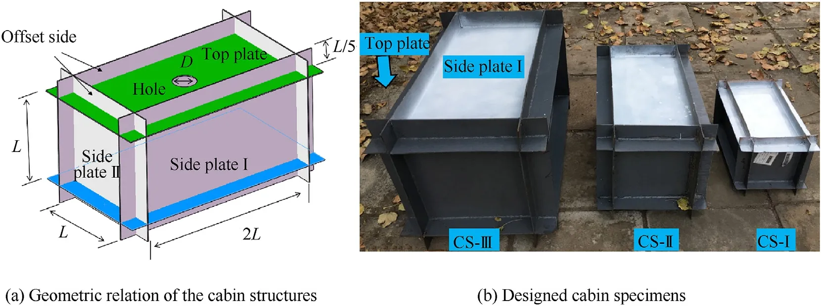
Fig.1.Test specimens: (a) Geometric properties of the cabin structure; (b) Designed scaled-down models.
As depicted in the figure, it can be seen that the overall deformation of the Side Plate I and II and the offset sides was gradually increased with the increase of the explosive mass.An obvious bulge was found for the Side Plate I formed by plastic hinges combined with inwards deformation at the corners and buckling at the offset sides in CS-III specimens, as shown in Fig.4.In addition, the deformation characteristics of the specimens with the same scaling factor (i.e.in each column) were similar.In addition, An inward plane buckling was indicated at the central parts of the offset sides,which was likely caused by the vertical tensile stress induced by the outward bulging occurred at the center of both the top and side plates.
However, an obvious difference was indicated in the final deflection of the deformed side plate.As shown in Fig.5, even though the effects of the scaling factor were eliminated, the final deflection values obtained from the central line of the Side Plate I for different specimens still showed some inconsistency, in particular for the CS-I-1.
Based on this observation,the center point deflection of the Side Plated I(both sides)and the corresponding deflection-to-thickness ratio values are summarized in Table 5.Fig.6 demonstrates the evolution of the latter as a function of the explosive mass.In addition to the increasing trend for all the curves,it should be noted that, the deflection-to-thickness ratio of the model specimens in different scaling factors exhibited different values for all the given explosive masses, ranging from 16.3% to 33.5%.This observation implies that, in addition to the scaling factors, some other important factors, e.g.the strain-rate effect, are possibly have impacts on the dynamic response of the cabin structures.Therefore,the traditional scaling law should be modified when applying for predicting of the dynamic behavior of the cabin structures.

Table 5 Plate center deflection.
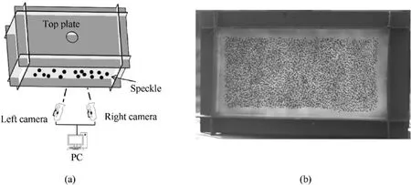
Fig.2.DIC test system:(a) Schematic diagram; (b) speckle.

Fig.3.The overview of deformation scenarios happened in cabin structure models after explosive tests (CS-II and CS-III scaled down).
The DIC-measured dynamic response of the Side Plate I in the case of CS-II-1 is shown in Fig.7.A shock wave was generated once the PETN explosive was detonated and radially propagated to the Side Plate I within a short time.As a consequence, the central region of the Side Plate I was firstly deformed (see Fig.7 (a)).Following that, deformation propagated from the center to the corners (see Fig.7 (b)).Due to the high deformation speed in the central region, the deformation characteristics of the entire plate become bulging outward from the center (see Fig.7 (c)).After reaching the maximum deflection, the deformation in the central area showed a slight spring back(see Fig.7 (d)).
In order to clearly characterize the deformation process of the Side Plate I, four measurement points were set for the DIC measurement,as indicated in Fig.8.Apparently,the displacement-time histories of all the selected points showed similar trend.The maximum deflection (27.7 mm)was achieved by the central point P0 at around 1.2 ms.P1 and P3 points exhibited similar deflection while the minimum one was found in P2 points.Taking P0 as an instance,an obvious drop was found after the peak value,indicating the rebound of the plate.From that onwards, the curve showed slight oscillation and gradually stabilized at around 23.8 mm.
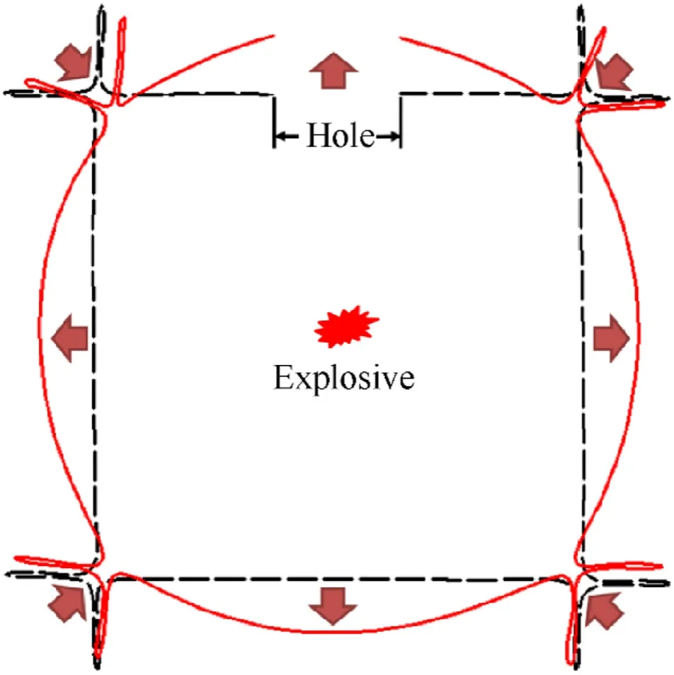
Fig.4.Comparison of section deformation between experiment case CS-III-3 and original model (Red outline is the deformed shape).
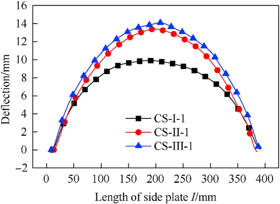
Fig.5.Comparison of deformation curves of central section of the Side Plate I in experiment cases of CS-I-1, CS-II-1 and CS-III-1 (scaled-down).
Owing to the differences in the final deflection of the specimens shown in Fig.6,it is necessary to detect the evolution of the internal blast pressure within the cabin during the explosive tests.Fig.9 illustrates the comparison of the pressure curves as a function of loading time for the SP1 point in the CS-I-1,CS-II-1 and CS-III-1.Note that the values obtained from the latter two cases were divided by 1.5 and 2, respectively.The comparison results demonstrated similar initial shock wave peaks with consistent starting time for the three cases.The subsequent evolution trend was also similar despite of the significant oscillations, which was induced by the complex reflection of shock waves inside the cabin.
Fig.10 shows the comparison of pressure evolution history of different measurement locations, i.e.SP1 and SP2, in the experiment case CS-I-1 under internal blast loading.Generally, both measurement points showed similar evolution trends,in particular for the final quasi-static parts.The most significant difference appeared at the initial stage.SP 2 point achieved around 3 MPa peak pressure,which was higher than its S1 counterpart(1.5 MPa).This was owing to its corner position, which possibly formed a concentration of the shock wave.Following that, a series of pressure oscillations were found for both of these points and showed a gradual reduction until the end of the loading process.
The quasi-static pressure is a static-like pressure load with a longer duration, which is a key factor for characterizing the structural response to internal blast loading.Anderson et al.[28] proposed an empirical formula of the quasi-static pressure by fitting the experimental data, which is expressed as:
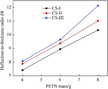
Fig.6.Relationship between plate center deflection-to-thickness ratio and PETN mass.
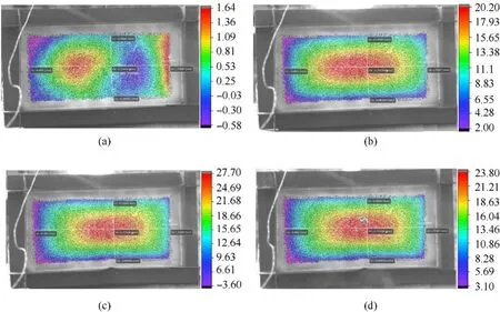
Fig.7.Deformation process of the Side Plate I in the case of CS-II-1: (a)0.2 ms; (b)0.8 ms; (c)1.27 ms; (d)10 ms.

whereis cabin structure volume,is the ambient pressure,andis the explosive energy.
The quasi-static pressure values gathered from the experimental results and calculated by using Eqs.(1) and (2) are summarized in Table 6.The results, including both the initial shock wave and the quasi-static pressure, exhibited a reasonable agreement for each loading condition.Consequently,the potential effects of internal blast pressure and quasi-static pressure on the differences in the final deflection can be neglected.
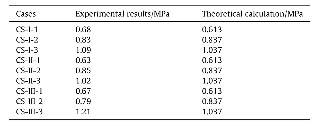
Table 6 Quasi-static pressure.
3.Numerical studies
Explosion tests have many constraints relating to safety problems and excessive costs [29].Thus, numerical studies can be a more appropriate approach than the experimental approach because it is a safe and cost-effective method,so we use numerical studies to deeply analyze the results.
3.1.Finite element model
The commercial code ANSYS/AUTODYN was implemented to establish a finite element model with the same size as the experimental specimen, as shown in Fig.11.The fluid-solid coupling algorithm was adopted to simulate the interaction between blast wave and the cabin structure.Taking the CS-I as an example, the mesh size of structure and air were both defined as 5 mm.Thus,the total element number for structure and air were 27776 and 360000,respectively.
The size of the spherical explosive was determined according to the PETN mass used in the blast tests.It was filled into the air with part fill setting.Flow-out boundary was given to the air on both sides of the area.Gap size was set as 0.64 mm for the contact and a full coupling was adopted.
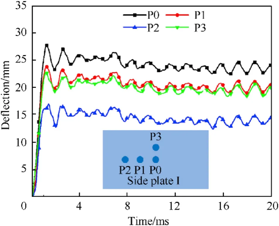
Fig.8.Displacement-time histories of each point of Side Plate I of CS-II-1.
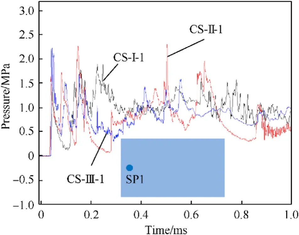
Fig.9.Pressure evolution histories of the SP1 in the cases of CS-I-1, CS-II-1 and CS-III-1.
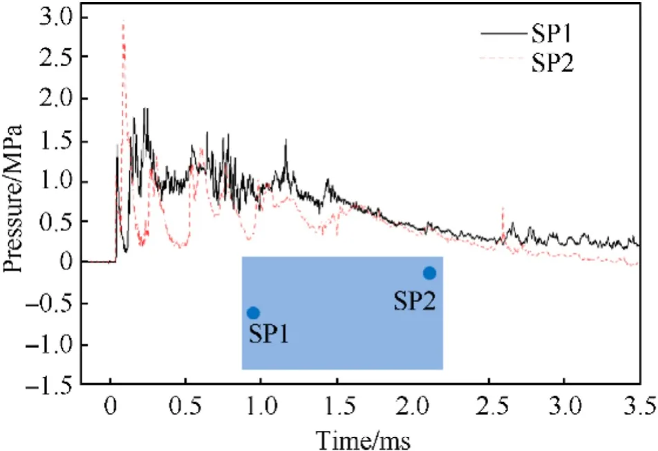
Fig.10.Pressure time history of different measurement points in CS-I-1.
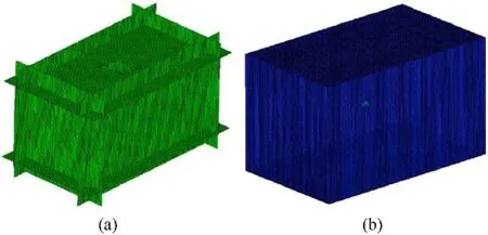
Fig.11.Finite element model of tested specimen:(a)cabin structure model;(b)air and explosive model.
3.2.Material model and parameter
In the modelling process, the Jones-Wilkins-Lee (JWL) status equation was utilized to simulate the pressure generated by the explosion:

whereis the relative volume of the explosive material,=ρ/ρ.ρand ρare the density of the explosive material and the detonation products.,,,and ωare material constants.is the specific internal energy.The material properties of PETN and the relevant parameters are listed in Table 7.andare the velocity of detonation and the Chapman-Jouguet pressure,respectively.
Cowper-Symonds material model was used to simulate the dynamic behavior of the steel cabin boxes.The general equation of Cowper-Symonds model is presented as:

According to our previous research [30], the values of the relevant material parameters are shown in Table 8.
3.3.Sensitivity study of the element size
Considering the impact of the element size on the convergence and accuracy of the simulation results, a mesh calibration study[31] was carried out prior to the further analysis.The CS-I-1 was taken as the instance.Different element sizes, i.e.2 mm, 5 mm,10 mm and 20 mm, were adopted and the comparison results on the deflection magnitude is shown in Table 9.To balance the computing efficiency and accuracy,the element size was selected as 5 mm.

Table 7 Material parameters of PETN.

Table 8 Parameters of Cowper-Symonds material model for steel box.

Table 9 Analysis on the element size sensitivity of the FEA.
3.4.Strain rate effect verification
The dissimilar response of the scaled cabin structure could be caused by many factors,e.g.gravity,material strain rate,machining errors, but strain rate effects were identified as the main factor in giving rise to the deviations between the results[32,33].So in this section,we use the simulation method to verify the importance of strain rate to the scaling law of cabin structure under internal blast loading.
Bilinear hardening material model was used in the numerical studies in order to evaluate the effects of the strain rate during the scaling analysis.The central point deflection of the Side Plated I is indicated in Fig.12.Obviously,the deformation process of the Side Plate I demonstrated consistent trend for the three cases, only the values of deflection were slightly different.One should note that,to facilitate a reasonable comparison,the time axis and deflection axis in the cases of CS-II and CS-III were scaled down by 1.5 and 2 times,respectively.The pressure of the SP1 also demonstrated similar evolution trend for the three cases, as shown in Fig.13.Based on these observations in Figs.12 and 13, it can be indicated that the deflection of the cabin structure made by strain rate insensitive material under internal blast loading satisfied the Hopkinson’s scaling law.Consequently, the dissimilar response of the scaled cabin structure was mainly caused by the strain rate effect.
3.5.Numerical results
Similar to the experimental results,the dynamic behavior of all the simulated cases exhibited similar trends.Therefore, only the deformation process of the case CS-I-1 was shown in this section,as illustrated in Fig.14.It can be clearly indicated that, during the entire blasting process, the overall deformation was initiated from the central point of all the Side Plates (i.e.I, II and top) and propagated towards the corners,which resulted in an outward bulging for the Side Plates.In addition, the offset sides showed an inward buckling at the central parts.All these findings indicated an excellent consistency to the scan results for the tested specimens shown in Section 2.2.2.
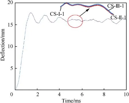
Fig.12.Central displacement-time histories of numerical results under CS-I-1,CS-II-1 and CS-III-1.
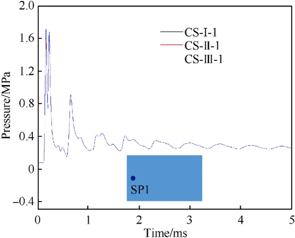
Fig.13.Pressure-time histories of numerical results under CS-I-1, CS-II-1 and CS-III-1.
The comparison of the experimentally and numerically obtained displacement-time curves of the central point (i.e.P0) in CS-II-1 and CS-III-1 specimens are respectively shown in Fig.15.In addition, the deflection-to-thickness ratio of the central point (i.e.P0) in all the considered cases obtained from two approaches are plotted in Fig.16.All the results exhibited a reasonable agreement,which provides a further validation for the developed finite element model.Based on the validation,the developed model was utilized for a further study on the modification of the scaling law in the next Section.
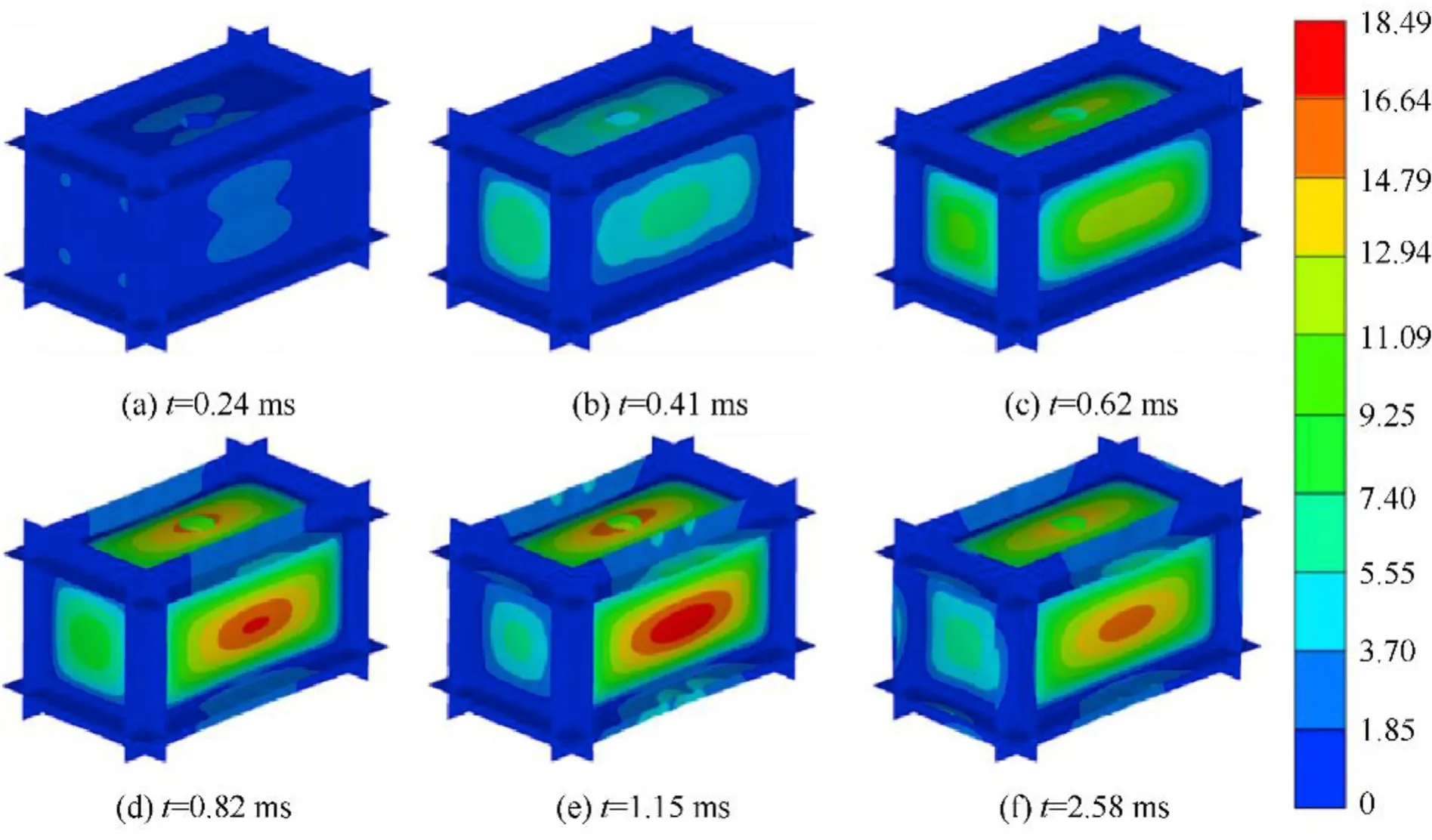
Fig.14.Numerical result of the deformation process of the specimen in CS-I-1.
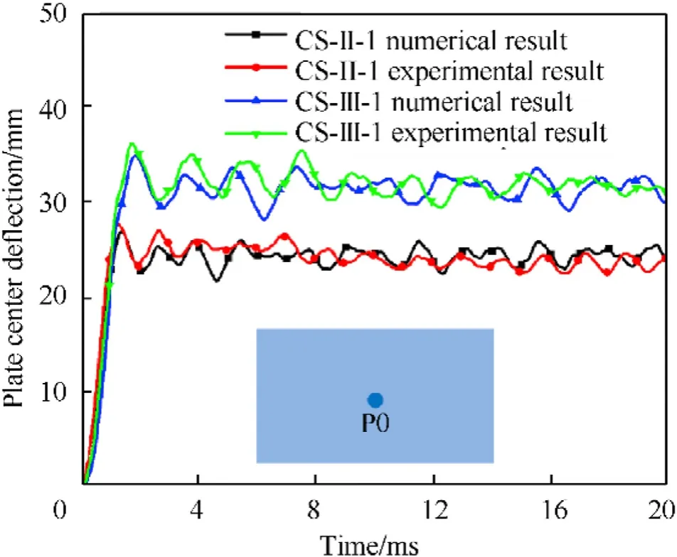
Fig.15.Central displacement-time histories of numerical and experimental result under CS-II-1 and CS-III-1.
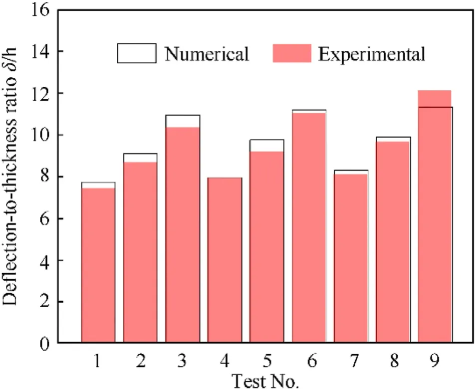
Fig.16.Comparison of the experimentally and numerically obtained deflection-tothickness ratio of the central point (i.e.P0) of every specimens.
4.Discussion
4.1.Effect of strain-rate ˙ε on deflection
When steel plates are subjected to internal blast loading, their dynamic response can be determined once the relevant conditions are given, such as the boundary conditions, the mass of the explosive and the volume of the cabin structure.Thus, the deflection under explosive loading can be described by a set of parameters as follows, characteristic length of the structure, stand-off distance, thickness of the plate, mass of explosive, the shockwave impulse per unit area of the plate, material density ρ,dynamic yield stress of material σ,effective plastic strain ε,Strain rate ˙ε.Deflection can be expressed as a function:

As the explosive is located in the center of the cabin,the standoff distance=/2,which can be neglected in the above equation.A set of fundamental dimensions comprised of dynamic yield stress of material σ, material density ρ, and thickness of the plateare selected to give the following dimensionless κ terms:

Thus the deflection-to-thickness ratio can be expressed as:

The similar relationship regarding on the dynamic response between the scale-down models and their prototypes could be achieved if each term of the models was kept equal to their counterparts in the prototype.Owing to the same materials and similar configuration between the prototypes and their models, it can be obtained based on Table 1 that:

In order to satisfy the similar relationship of the deflection between the scale-down models and the prototype,each value of the model to prototype ratio, as show in Eq.(9), should be equal to 1.


It should be noted that different constitutive models may lead to different expressions of similarity laws.The Cowper-Symonds model was adopted in this work to discuss the effect of the strain rate effect because it is one of the typical material models used to characterize the high strain rate dynamic behavior of metallic materials.
Based on the Cowper-Symonds model, the deviation caused by the geometric reduction ratio at different strain rates is

It can be known from Eq.(10)that the deviation caused by strain rates are quite obvious.Given the scale factor as 2,1.33,and 1, the deviation in σratio is shown in Fig.17.It can be seen that, as the strain rate increases, the increase of the deviation of the scaledown model is more significant than that of the prototype.
4.2.Effect of scaling factor β and scaled distance Z on deflection-tothickness ratio δ/h

The numerical results shown in Fig.18 (a) indicated that the deflection-to-thickness ratio was gradually decreased with the development of the scaling factor while was significantly decreased with the increase of the Hopkinson scaled distance.The best fit curved surface of the deflection-to-thickness ratio of the center point of Side Plate I as a function of the scale factor and the scaled distance is shown in Fig.18(b).The fitting formula is expressed as:

5.Conclusion
In this paper, the dynamic response of geometrically similar cabin structures subjected to internal blast loading were investigated through a series of experiments and numerical studies.According to the Hopkinson’s scaling law,three sets of cabin structure models with different scaling factors combined with different explosive masses were designed for the experimental parts.The dynamic deformation process of the model was recorded by using the DIC method and a 3D scanning technology was used to reconstruct the failure mode of the specimen.In addition, a finite element model was developed using the commercial software ANSYS/AUTODYN to perform a parametric study and for the modification of the scaling law.Based on the experimental and numerical studies, some conclusions can be drawn:
• The experimental results indicated that, the evolution trends and deformation modes of the different cabin structures designed with geometry similarity are almost similar.The evolution trends of all side plate shows an obvious rebound effect,and the deformation modes of all side plate are outward bulging produced.
• Despite of the similar evolution trends and deformation modes,the final deflection of the side plates in the cabins showed apparent differences even though the scaling factor was eliminated.As the strain rate and scaled factor increases,the increase of the deviation of the scale-down model is more significant than that of the prototype.
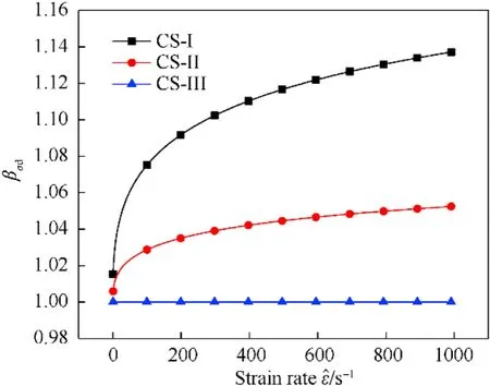
Fig.17.Effect of strain rate of cowper-symonds model on βσd.
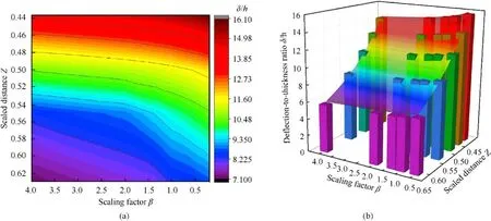
Fig.18.Effect of scaling factor and PETN mass on deflection-to-thickness ratio.
• The numerically obtained dynamic response of the cabin specimens showed a good agreement with that gathered from the experiments.Based on the proposed model, the scaling law for cabin structures was modified considering the scaling factors and scaled distance.An empirical expression on deflection-tothickness ratio was given, which can be used to modify the results for the up-scaling of the model in similarity research.
The authors declared that they have no conflicts of interest to this work.
The authors would like to thank the support from the National Natural Science Foundation of China under Grant No.11902031 and No.11802030 and No.11802031.Beijing Municipal Science and Technology Project Management Approach under No.Z181100004118002.
杂志排行
Defence Technology的其它文章
- Behind-plate overpressure effect of steel-encased reactive material projectile impacting thin aluminum plate
- Numerical damage evaluation of perforated steel columns subjected to blast loading
- Effect of hydrogen-storage pressure on the detonation characteristics of emulsion explosives sensitized by glass microballoons
- Blast responses of polyurea retrofitted utility tunnel reinforced with basalt fibre reinforced polymer bars
- Experimental study on the accumulative effect of multiple pulses on acceleration sensor
- Higher-order electroelastic modelling of piezoelectric cylindrical nanoshell on elastic matrix
