Behind-plate overpressure effect of steel-encased reactive material projectile impacting thin aluminum plate
2022-05-24QingYuJihoZhngHongweiZhoYnwenXioHifuWng
Qing-o Yu , Ji-ho Zhng , Hong-wei Zho , Yn-wen Xio , Hi-fu Wng ,*
aBeijing Institute of Technology, State Key Laboratory of Explosion Science and Technology, Beijing,100081, China
bAcademy of the Rocket Force, Beijing,100094, China
cEquipment Project Management Center, Army Equipment Department, Beijing,100072, China
Keywords:Reactive materials Steel-encased reactive material projectile Over-pressure effect Overpressure limit velocity Energy release
ABSTRACT Ballistic impact and sealed chamber tests were performed on the steel-encased reactive material projectile (SERMP) to understand its behind-plate overpressure effect when impacting the thin aluminum plates.The reactive material encased with a 1.5 mm thick 30CrMnSiNi2A steel shell was launched onto the initially sealed test chamber with a 3 mm thick 2024-T3 thin aluminum cover plate.Moreover, the overpressure signals in the test chamber were recorded by pressure sensors.The experimental results indicate an unusual behind-plate overpressure effect: as the density of the projectile increases from 6.43 g/cm3 to 7.58 g/cm3 by increasing the content of tungsten powder, although its total chemical energy decreases, it produces a higher behind-target overpressure at a lower impact velocity.A theoretical model is proposed to predict the reaction length of reactive material inside the projectile based on one-dimensional shock wave theory to understand this unexpected result.In addition, the deviation between the actual energy release and the theoretical calculation results, also the variation of overpressure rise time are analyzed and discussed.As the analyses show, when the SERMP successfully penetrates the cover plate, an increasing density of the reactive material inside the projectile always means that the delaying rarefaction wave effect,an increase of its internal pressure and strain rate levels.These factors lead to the increase of the overpressure limit velocity and reaction extent of the reactive material, while the overpressure rise time decreases.
1.Introduction
Reactive material projectiles are a class of novel energetic projectiles which can produce violent deflagration reaction under intensive dynamic loading, cold isostatically pressed and sintered Polytetrafluoroethylene (PTFE)/Al reactive material projectiles are the typical representative.Unlike traditional tungsten, steel, and other inert projectiles, reactive material projectiles can also form behind-plate overpressure damaged area.This mode of penetrating and exploding can significantly improve the damage power of ammunition warhead, which has attracted widespread attention from many research institutions of ammunition weapons at home and abroad in recent years [1-6].
In 2003, Joshi published a typical manufacturing process of PTFE/Al and noted that the reactive materials are a class of novel energetic composite materials, significantly different from traditional energetic materials due to its higher strength and density[7].Since then, researchers have carried out in-depth studies on the formulation process, mechanical properties, energy release characteristics, damage patterns, and other aspects of PTFE/Al [8-16].Taking into account the shortcomings of bomb calorimetry,Ames R G et al.investigated the energy release characteristic of the PTFE/Al reactive material projectiles and compared the energy release relationship between different material formulations by designing a vented chamber, also found that the energy release efficiency of the reactive material projectiles is a strong function of the projectile impact velocity [12,13].Wang H F et al.improved the vented chamber and proposed a method for dynamic measurement of the energy release characteristic of the PTFE/Al reactive material projectiles.Beyond that, the ignition and detonation, and damage characteristics of reactive materials on multilayer plates, shielded charge, and aviation kerosene were also studied [14,15].Through Taylor rod tests and Hopkinson pressure bar (SHPB) experiments,Raftenberg et al.studied the deformation and compressive mechanical responses of PTFE/Al [16].However, although compared with traditional energetic materials, PTFE/Al reactive material projectile have higher strength and density, but they are still far lower than inert projectile such as steel and tungsten.When impacting the thicker or harder target,it often breaks into amount of debris and reacts before the plate, cannot enhance the behindplate damage effect.
To address this, Cai investigated the effect of particle size of Al and porosity of W on the mechanical properties of materials from the perspective of the force chain and pointed out that W particle can effectively improve the compressive strength of the material,so as to avoid excessive loss of reactive materials in front of the target[17].Xu F Yet al.studied the influence of plate thickness and impact velocity on the behind-plate overpressure effect of the high-density reactive material projectile (PTFE/Al/W) through ballistic impact test and provided the optimal target thickness value to maximize behind-plate overpressure [18,19].Through the drop-weight test,Geng B Q et al.studied the influence of pressure on the density distribution of PTFE/Al/W and evaluated the impact-induced initiation characteristic of PTFE/Al/W[20].In addition,by adding highdensity metals,Nielson DB studied high-strength reactive materials that can be used as a reactive liner in penetrating (shape-charge)warheads, also the reactive material can be safely processed at temperatures significantly below the thermal autoignition point of the reactive material [21].All these studies show that, compared with PTFE/Al reactive material projectiles,the addition of tungsten powder does improve the comprehensive performance of the reactive material projectiles.However, the content of tungsten powder cannot be increased indefinitely, otherwise the impact deflagration characteristics of the reactive material projectiles cannot be guaranteed, which makes the ultimate strength of the good-performance PTFE/Al/W reactive material projectiles only about 100 MPa.In the face of thicker or harder targets, it is still unable to achieve efficient damage to the target.
In fact, in the further application of the reactive material projectile in the warhead, in order to solve the problem of the weak penetration performance of the reactive material projectile, our research group carried out a preliminary study on the inert-metalcased reactive material projectile.Through this method, more options are provided for the formulation of the reactive material inside the projectile,and makes it exhibit unusually good penetration and explosion performance.However, since the reactive material projectile reacts under the action of the transient shock wave generated during the impact, and the existence of the shell makes the reflection and transmission of the shock wave occur at the interface between the shell and the reactive material.In addition,the reaction of the reactive material projectile is also affected by the reflected rarefaction wave of the thin plate, while the shell makes the unloading relationship between the compression wave and the rarefaction wave more complex.As a result of the above two factors, the influence of the shell on the impact response of the reactive material has not been deeply understood, especially the unexpected behind-target overpressure effect of SERMP.Although the metal shell structure has been used in the studies of the reactive material projectile in literature[22-24],it was only used as a pure method to improve the penetration performance of the reactive material projectiles, but the internal mechanism has not been studied in depth.
In this paper, ballistic impact and sealed chamber tests were performed to understand the behind-plate overpressure of SERMP after impacting the thin aluminum plates.Moreover,the influence of the density of reactive materials and projectile impact velocity on the behind-plate overpressure effect is discussed and analyzed.The research results can provide useful guidance for the matching method between reactive materials with different densities and high-strength shells,so as to effectively enhance the damage power of reactive material projectile warheads.
2.Experimental arrangement
2.1.Preparation of SERMP
The raw materials included PTFE powder(average particle size:100 nm, density: 2.2 g/cm), aluminum powder (average particle size: 44 μm, density: 2.78 g/cm) and tungsten powder (average particle size:44 μm,density:19.35 g/cm).The physical properties of each component are listed in Table 1.
Under intensive dynamic loading, PTFE in the reactive material is sublimated and decomposed by transient shear.As an oxidant in the reaction system,Gaseous PTFE undergoes a violent deflagration reaction with Al,and its reaction product C undergoes a secondary reaction with W.The chemical reaction equations are shown in Eqs.(1)-(3).

Because WC and C have high melting and boiling points,they are all distributed in the chamber in the form of solid particles,and the gas in the reaction products is mainly AlF.It is worth noting that due to the very stable chemical characteristics of tungsten powder,the reaction of Eq.(3) only accounts for a tiny part of the whole reaction.Therefore,the primary function of tungsten powder is to serve as the rigid support point inside the reactive materials and to improve the strength and density of the reactive materials [25].It can be obtained from the above reaction equations that the stoichiometric weight percentage ratio of PTFE/Al is 73.5:26.5.Considering the reaction rate and reducing the influence of reaction between Al and external oxygen on the overpressure analysis,PTFE/Al under zero oxygen equilibrium ratio was used as the matrix to form three kinds of materials with different densities by controlling the mass proportion of tungsten powder.The basic parameters of reactive materials under various formulations are shown in Table 2,where TMD represents the theoretical maximum densities.
The preparation of the reaction materials mainly includes the steps of mixing components, cold isostatic pressing, and hightemperature sintering.First, the PTFE, Al, and tungsten powder were added to an anhydrous ethanol solution and mixed by a blender for about 40 min, followed by a drying process at room temperature lasting for 48 h, and then the mixed powder was placed in a mold with an inner diameter of 10 mm and a cold uniaxial pressure of 250 MPa.After that,the pressed samples were sintered at high temperatures and cooled under the protection of the argon environment.This process can effectively improve the compactness of the reactive materials and bonding performance of PTFE.
After getting the ∅10×8 mm reactive material,put it in the preprocessed 30CrMnSiNi2A steel shell and connected the cap with the shell by laser welding after close matching.The shell thickness is 1.5 mm,and the resulting SERMP structure is shown in Fig.1,and Fig.2 is its physical picture.The overall density of the projectiles formed by the three reactive materials A,B,and C was measured by the drainage method,which was about 6.43 g/cm,7.06 g/cmand 7.58 g/cm, respectively.The specific parameters are listed in Table 3, in which ρ,,,refer to the projectile density, the mass of the projectile, the mass of the shell, and the mass of the reactive material.

Table 1 Summary of element properties of PTFE/Al/W.

Table 2 Typical samples with different content of PTFE/Al/W.

Table 3 Basic parameters of typical experimental projectiles.
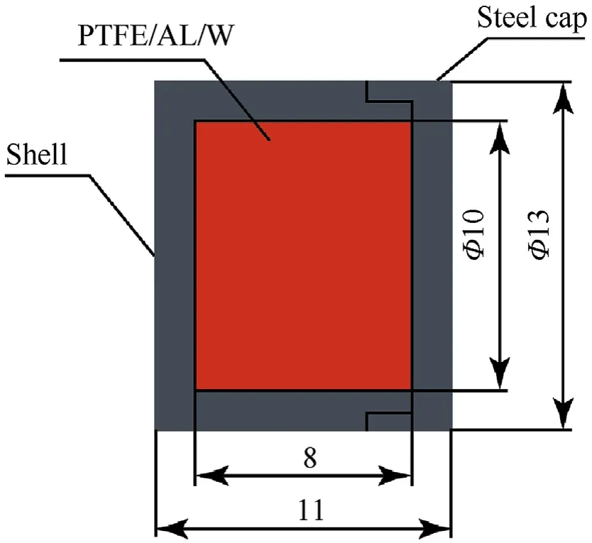
Fig.1.Schematic of the SERMP.
2.2.Overpressure test chamber
The basic structure of the overpressure test chamber is shown in Fig.3(a).Fig.3(b) is the photograph of the overpressure test chamber.It was a cylindrical steel chamber with an inside and outside diameter of 260 mm and 340 mm,respectively,a length of 500 mm and a volume of 26.5 L.The front of the chamber was closed with a 3 mm thick 2024-T3 thin aluminum cover plate and sealed with a rubber gasket at the threaded connection.A rectangular high strength plexiglass window (PMMA) was set on the chamber wall to observe the experimental phenomena.The front plate,rear plate,and PMMA window were fixed and sealed utilizing flanges and gasket materials.There were also three evenly distributed test channels on the sidewall of the chamber,and Ak-1 high-precision strain pressure sensors (China Academy of Aerospace Aerodynamics)were installed on each channel to record the pressure inside the chamber.The sensor range was 0-1 MPa, and the sensitivity of,andsensors were 0.249, 0.232, and 0.232 MPa/V under the calibration condition of 0.5 MPa, respectively.The distance between each sensor was 120 mm.
2.3.Experimental setup
The experimental test setup is shown in Fig.4.The entire experimental system comprises the projectile loading system,sensor velocity measuring system, and terminal overpressure testing system.The axis of each system was adjusted in the same horizontal line to ensure the stability of the projectile flight and overpressure signal test.
The central part of the projectile loading system was a 14.5 mm ballistic gun launcher.Place the SERMP with sabot into the ballistic gun.The impact velocities were controlled between 600 m/s and 1100 m/s by adjusting the mass of the black powder.To ensure the separation of reactive material projectile and sabot, the distance between the muzzle and the plate was 8 m.
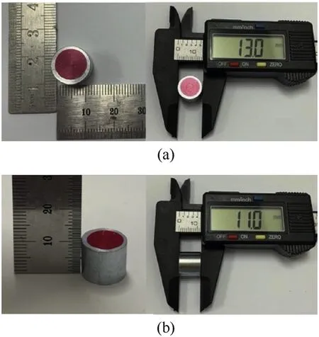
Fig.2.Typical photographs of SERMP:(a)the diameter of the projectile;(b)the height of the projectile.
The velocity measuring system was mainly composed of velocity probes and an electronic timer.The distance between the front plate and the probe was 320 mm, and the distance between each probe was 200 mm.The velocity measured by the velocity probes was taken as the final impact velocity and used to calculate the initial pressure of the impact surface.
The terminal overpressure testing system was composed of an overpressure test chamber and a high-speed video.A TST3206 data acquisition system was used to record the overpressure signals in the test chamber.The process of SERMP commonly impacting the test chamber was recorded by high-speed video, with the frame rate,resolution,and exposure time were set as 8200 fps,640× 480 pixels, and 40 μs, respectively.
3.Experimental results
The overpressure signals obtained at the Schannel in the test chamber are shown in Fig.5.In particular,the differences between the real pressure history and the quasi-static pressure are shown in Fig.5(a).The Behind-plate overpressure effect of SERMP due to impact is investigated by using quasi-static pressure curves,which is consistent with the treatment method in Ref.[26].It is shown that with the increase of measuring time,the changing trend of all overpressure curves can be divided into two stages.The first stage is the rapid rise of overpressure, lasting about 10-25 ms, and the corresponding process is the deflagration reaction of the SERMP in the chamber.The second stage is the slowly decreasing stage of overpressure, lasting for hundreds of milliseconds, and the corresponding process is the sustained heat exchange between the chamber and the external environment, which is mainly manifested as the outflow of deflagration gas product from the puncture.
The statistical results of the peak overpressure obtained from each quasi-static overpressure curve are shown in Table 4.It can be seen that the peak overpressure of SERMP is significantly affected by the projectile density and impact velocity.First of all, under a similar impact velocity,the peak overpressure of Type-C projectile is higher than that of Type-A and B.Especially when the impact velocity of type-C projectile is 851 m/s, the peak overpressure can reach 0.230 MPa.In comparison, the peak overpressure of type-A projectile is only 0.168 MPa at the impact velocity of 942 m/s.This is a rather unexpected result.On the one hand,compared with Type-A SERMP,the impact velocity of Type-C SERMP is lower.That is,the initial shock pressure received by the projectile is lower.On the other hand,with the increase of tungsten powder content,the total chemical energy of Type-C SERMP also decreases.Under such conditions,the behind-target overpressure would decrease for bare reactive material projectiles, but the results showed that Type-C S ERMP produced a higher behind-target overpressure.

Fig.3.Schematic of the overpressure test chamber and photograph of the test chamber.
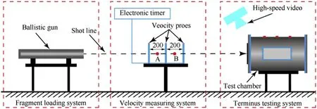
Fig.4.Schematic of the behind-plate overpressure effect test system.
In addition, for the C-type projectile, the peak overpressure generated by the projectile increases with the increase of the impact velocity,which is consistent with the experimental rules of the bare reactive material projectiles [27].However, in the overpressure test experiment of A-type projectiles,although the impact velocity of the 4#and 5#experiment is higher than that in the 3#,the peak overpressure does not increase significantly.The same result is also seen in the test experiment of B type projectile.Namely, when the velocity of SERMP impacting the thin target exceeds limit velocity, the behind-target overpressure does not increase monotonously with the increase of impact velocity, but changes near a specific stable value.For Type-A and Type-B projectile, it can be seen from Table 4 that the overpressure limit velocity is within the range of 869-1013 m/s and 915-1048 m/s,respectively.
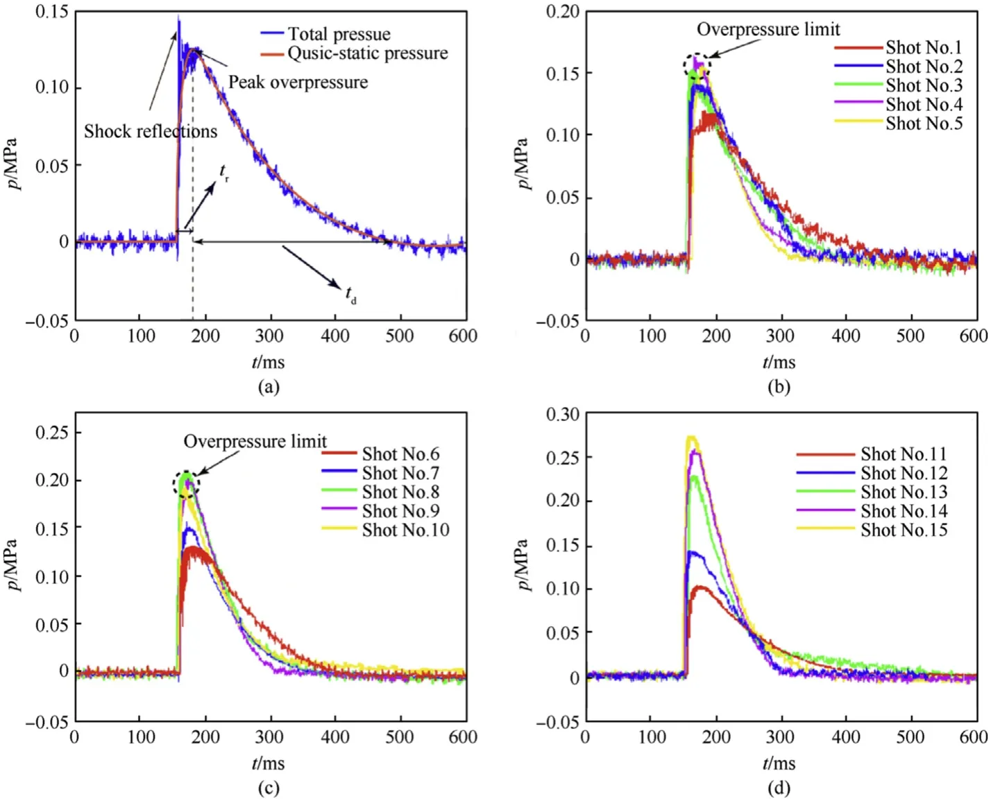
Fig.5.Behind-plate overpressure curves in the test chamber.(a) Differences between total pressure and quasi-static pressure.(b) Overpressure curves of Type-A SERMP in the S2 channel.(c) Overpressure curves of Type-B SERMP in the S2 channel.(d) Overpressure curves of Type-C SERMP in the S2 channel.

Table 4Experimental results.
Fig.6 displays the typical high-speed video frames of C-type SERMP when they impact the overpressure test chamber at two velocities, respectively.It can be seen from the second frame at 0.05 ms in the figure that after the SERMP penetrates the cover plate,partial fracture and initial ignition occur first.Immediately after,the deflagration reaction expands in the reactive material,and the flame brightness at the observation window reaches its maximum after 12-13 ms, as can be seen from the fifth frame at 12.8 ms, which is corresponding to the peak in the overpressure curve.By comparison,it can be found that the flame brightness in Fig.6(a)is higher than that in Fig.6 (b), which indicates that the former has a higher reaction extent, mainly due to its higher impact velocity.
Further observation reveals that two major stages of reaction of the reactive material can be identified:reaction confined by casing material and reaction in dispersed debris.In the first stage, the SERMP penetrates the cover plate,and the breakage and ignition of the reactive material are confined to the inside of the shell.The firelight observed is extremely weak before the shell is broken, as can be seen from the 1st and 2nd frames for both figures(a)and(b).In the second stage, the shell is broken under radial mechanical stress and internal deflagration pressure,and the reactive material reaching the fracture limit is dispersed in the test chamber in the form of debris, leading to the violent deflagration, as can be seen from the 4th and 5th frames for both figures(a)and (b).
Of course, in addition to some reactive materials involved in deflagration reaction, residual projectiles would be formed in the part of SERMP that does not reach its reaction threshold.Some of them are reactive materials of irregular cylinders which do not reach the critical fracture threshold.However, some large fragments which reach the critical fracture threshold but do not reach the reaction threshold are also included.Practically, the predominant existence form of the residual projectile is closely related to the reactive material formula, particle size, preparation process,impact condition and other factors.Due to the effect of high temperature and high pressure,it would burn slowly and form fireballs in the test chamber.Finally, as the reaction products in the test room continuously leak from the puncture and diffuse in the external environment, the brightness of the observation window gradually diminishes.the average duration of this stage was about 160 ms, which was corresponding to the second stage of the overpressure curves.
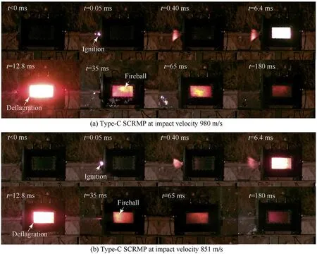
Fig.6.Typical high-speed video frames of SERMP.
4.Discussion
4.1.Description of the impact reaction process
There is an apparent difference between the impact reaction process of SERMP to thin targets and that of the bare reactive material projectiles,and the former is even more complicated.The impact reaction process of the SERMP is affected by the shell from three main aspects.
First of all, the bare reactive material projectile breaks into a large number of debris in the penetration process,and the debris is ejected from the front of the plate, leading to mass loss [28].For SERMP, the shell greatly enhances its penetration ability and can ensure all the reactive material into the overpressure test chamber.
Secondly, the propagation of shock waves between the projectile and the plate is affected by the shell, especially a series of transmitted and reflected waves are generated at the interface between the reactive material, shell, and plate, which affects the pressure and strain rate level inside the reactive material.As the deflagration reaction of the reactive material occurs under specific loading pressure and strain rate threshold[29],the impact reaction of the reactive material is affected by the shell.
Finally,when the projectile successfully penetrates the target,a violent deflagration reaction occurs.Compared with bare reactive material projectile,the energy released by SERMP is not only used for the expansion of deflagration products and the increase of internal energy of the product but also used for the deformation and fragmentation of shell and the flight of steel fragments.To better understand the impact reaction process of SERMP, the impact reaction process of SERMP is divided into three stages according to the impact-induced reaction characteristic of the reactive material combined with typical high-speed video frames, see Fig.7.
The first phase is shown in Fig.7(b).The two shock waves generated during the impact propagate forward to the front plate and backward into the SERMP,respectively.For SERMP,the shell is subjected to intense shear, and stress concentration occurs at the corner of the shell, the whole projectile undergoes high-stain-rate plastic deformation.Due to the difference of Poisson’s ratio between the reactive material and the steel shell,the radial expansion of the reactive material is more obvious during the impact process.Therefore,the front side shell moves in radial direction to cause the crush effects under the radial stress.Moreover, when the strain of the material reaches its critical fracture value, the initial separations occur at the embedded metal particle-polymer interfaces,resulting in cracks in the material.Conventionally, the ignition delay time of the reactive material is about 10-15 μs when the impact velocity varies in the range of 600 m/s~1200 m/s [28].During this period, the projectile can penetrate the entire 3 mm thick thin plate and enter the test chamber,so the reactive material does not react at this stage, and under the constraint of the shell,the reactive material has no mass loss.
The second phase of the impact reaction process is shown in Fig.7(c).At this time,the projectile has wholly penetrated the plate,and much crushing occurred at the front end of the shell, which made it lose the constraint for the reactive material.The reactive material breaks into a large number of debris and flies out from the front end of the shell.Among them,the debris with a large specific surface area first produces an ignition reaction,which locally forms a weak deflagration reaction.

Fig.7.Typical impact reaction behavior of SERMP.
The third phase of the impact reaction is shown in Fig.7(d).Compared with the second stage, more reactive materials participate in the deflagration reaction,releasing a large amount of energy into the chamber, and the remaining shell is broken under the action of the expansion of a large number of deflagration products.In addition, due to the non-self-sustaining nature of the deflagration reaction of the reactive material,its internal parts that do not meet the pressure and strain rate threshold formed residual projectile.The residual projectile is burned slowly in the high-temperature environment inside the chamber.However, compared with the heat loss and venting effects, the exothermic reaction of the residual projectile slows to a negligible degree.
Actually, the impact reaction process of SERMP is affected by impact velocity, parameters of the plate, parameters of the shell,and other factors.However,its necessary process is consistent with the above description.
4.2.Impact-induced reaction length
In general, when the loading pressure and strain rate in the projectile are higher than the threshold value,violent deflagration occurs in the impact process of the projectile [30].In order to analyze the impact-induced reaction characteristic of SERMP, a prediction model of the reaction length of reactive materials is proposed based on the one-dimensional shock wave propagation theory.Complex shock wave propagation occurs during the impact,including attenuation, transmission, and reflection of the shock wave.
The simplified shock wave propagation is shown in Fig.8.Firstly,a left traveling compression wave and a right traveling compression wave produced on the surface A1-A2 propagate forward into the plate and backward into the SERMP, as shown in Fig.8(a).Subsequently, the left traveling wave forms a reflected wave and transmitted wave at the interface B-Bbetween the shell and the reactive material.The transmitted wave is transmitted into the interior of the reactive material,and when the right traveling wave propagates to C-Con the free backside of the aluminum target,an unloading rarefaction wave with faster propagation velocity is formed, as shown in Fig.8(b).Finally, the rarefaction wave is reflected and transmitted twice at the interface A1-A2 and B-B,in which the transmitted rarefaction wave propagates into the reactive material chase and unload the compression wave that has propagated inside the reactive material, as shown in Fig.8(c).
On the initial impact surface A-A, based on the momentum conservation relationship and interface continuity conditions, the initial impact pressure at A-Acan be described as follows:

where:ρ is the material density,is the impact velocity,is the impact pressure,is the shock wave velocity,is the sound speed,andis the material coefficient.The subscripts 1 and 2 denote the shell and the plate, respectively.The shock wave velocityis expressed as:

where:is the particle velocity.The parameters used in the model are listed in Table 5.Each parameter of SERMP is based on the Voigt-Reuss-Hill mixing rules [31].

Table 5 Hugoniot impact parameters of different materials.

Fig.8.The simplified model of shock wave propagation of the SERMP impacting plate.
It is considered that the attenuation of the initial shock wave in the material is simplified to a simply shifted exponential.Therefore,the pressure amplitude after attenuation in the shell can be expressed as [27]:

where:is the pressure amplitude after attenuation in the shell,α is an empirical constant related to material property,the α of steel is 0.0543 mm,is the thickness of the shell.
After attenuation in the shell, the reflected wave and transmitted wave are formed at the interface B-B.According to the interface continuity condition, the amplitude of the transmitted wave can be expressed as:

where:is the amplitude of the transmitted wave.
The internal strain rate of the reactive material can be obtained by the ratio of the internal particle velocity to the length of the material,which applies to the short length of the reactive material[30].Combined with Eqs.(4)-(7), the internal pressure and strain rate distribution of the active material can be expressed as:

where: β is the attenuation constant of the shock wave in the reactive material,is the distance that the shock wave propagates inside the reactive material,is the length of the projectile.As such,the distance,at which the pressure in reactive material projectile decreases to, and the distance, at which the strain rate in reactive material projectile decreases to ˙ε, are written as:

where:and ˙εare the pressure threshold and strain rate threshold of complete deflagration of the reactive material.It is influenced by many factors,such as particle size,component ratios,and preparation methods.The pressure threshold values of A, B,and C projectile bodies are 2.16 GPa, 2.54 GPa, and 2.98 GPa,respectively,by fitting the relationship between chemical energy of reactive substances and actual release energy under different impact velocities [32].
For the strain rate threshold, it needs to be determined by Hopkinson rod experiments under different strain rates.For the traditional formula of PTFE/Al,the strain rate threshold is 6500 s.However, for different formulations of PTFE/Al/W, experimental results show that the strain rate threshold is generally lower than 6500 s[24].In fact, through the calculation of Eq.(9), it can be found that the strain rate of all the projectiles in this experiment during the impact process exceeds 10,000 s.Therefore, for the three types of SERMP in this paper,the strain rate does not limit the reaction length of the reactive material, and in the subsequent analysis, the influence of Lon the reaction length of the reactive material can be excluded.
When impacting the plate,the right traveling wave reaches the rear of the plate.It would be reflected in the opposite direction and spread towards the projectile as a rarefaction.As can be seen from Fig.8,the left traveling compression wave and reflected rarefaction wave have the following propagation relationship:


Thus, the distance, at which the initial shock wave in the projectile is unloaded by the rarefaction wave, is described as:

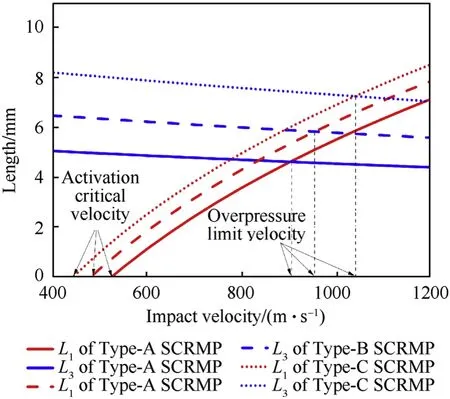
Fig.9.The effect of density and velocity on L1 and L3.
Based on the combined influences of loading pressure, loading strain rate, and rarefaction wave effect of the plate, the reaction length of reactive material can be expressed as= min (,).Using Eq.(10)- Eq.(15), the relationship betweenandis obtained, as shown in Fig.9.As can be seen from the figure, with an increase of impact velocity,show an increasing trend, whiledecreases continuously, where the intersection of curveand xaxis is the activation critical velocity () of the reactive material inside the projectile.By further comparing theand, it can be seen that when the impact velocity is small,the minimum value of the three is,and when the impact velocity is large,the minimum value of the three is.On the other hand, it can be seen that at similar impact velocities, with the increase of density, bothandincrease continuously.As a result,the limit velocity()affected by the rarefaction wave effect keeps increasing.It can be obtained that the limit velocity of A, B, and C projectile affected by the rarefaction wave effect is 905 m/s, 955 m/s, and 1040 m/s,respectively.
Therefore, with the increase of impact velocity, the changing trend of the reaction length can be classified into three cases according toand.When the impact velocity is less than,the reactive material cannot be activated, and the reaction length is always 0.When the impact velocity is greater than or equal tobut less than, the reaction length of the reactive material increases with the increase of the impact velocity.That is, the reaction length of the reactive material in this stage is determined by the attenuation effect of the shock wave.When the impact velocity is greater than or equal to, the reaction length of the reactive material decreases with the increase of the impact velocity.That is,the reaction length of the reactive material is affected by the rarefaction wave effect.
In fact, there is an upper bound on the impact velocity in the third case.This is because when the impact velocity is high enough to cause the projectile or target plate to undergo phase change or partial phase change, the mechanical properties of the material would change, and the multi-wave structure of shock wave and phase change wave would be generated inside the material.At this time, the change of the reaction length of the reactive material would be more complicated.Therefore, this paper only discusses the situation when the velocity is relatively low.
It should be pointed out that although the value ofdecreases with the increase of impact velocity,the change rate is low.As can be seen from the figure, when the impact velocity increases from 400 m/s to 1200 m/s,only changes by 0.5 mm.Therefore,it can be considered that when the SERMP impacts the thin targets, its limit velocity affected by the rarefaction wave is the overpressure limit velocity of the SERMP.The overpressure limit velocity Type-A and Type-B projectile is 905 m/s and 955 m/s,respectively,which is consistent with the results discussed in Section 3.However, the overpressure limit velocity of Type-C projectile is 1040 m/s,which is higher than the maximum impact velocity in the experiment.Therefore, the peak overpressure increases with the increase of impact velocity, as can be seen in Table 4.
According to Eqs.(4), (8) and (15), the internal pressure distribution of SERMP in 4#,13#, and 14# experiments are shown in Fig.10.TC in the figure represents the pressure transmission coefficient.It can be seen that at the impact velocity of 851 m/s and 980 m/s,the reaction length of the Type-C SERMP is determined by the attenuation effect of the shock wave because their impact velocity is lower than the overpressure limit velocity of the C-type projectile (1040 m/s).The initial pressure of SERMP in experiment 14#is higher on the front surface of the shell,and its peak value is 1.3 times of that in experiment 13#.Subsequently, a transmission wave is generated at the interface between the shell and the reactive material, with transmission coefficients of 0.85 and 0.88,respectively.As a result,the pressure of the reactive material inside the projectile in experiment 14# is still higher than that in experiment 13#.Therefore, when the impact velocity is 980 m/s, the reaction extent of the reactive material is greater,which leads to the higher brightness of the latter in the high-speed video,as shown in Fig.6.

Fig.10.Pressure distribution of internal materials of SERMP in experiments 4#,13#,and 14#.
By comparing the pressure distribution inside the projectile in experiment 4#and experiment 13#,it can be seen that due to the higher impact velocity in the 4#experiment,the initial pressure of SERMP is higher,which is 1.21 times of that in the 13#experiment.However, the transmission coefficient of 4# and 13# is 0.64 and 0.88,respectively.Therefore,for the experiment 13#,although the impact velocity is lower,the overall pressure of the internal reactive material is higher, so the value ofis larger.
In addition, as the impact velocity in the experiment 4# is higher than the overpressure limit velocity of Type-A projectile(905 m/s),the reaction length of reactive material is determined by the rarefaction wave effect.It can be seen from the figure that the unloading position of pressure in experiment 4#is 0.6 times that in experiment 13#.That is, theandin experiment 4# are both lower than the value in experiment 13#, which leads to a greater the reaction extent of the reactive material in experiment 13#,resulting in a higher overpressure in the overpressure test chamber,see Table 4.
4.3.Behind-plate overpressure analysis
Once the aluminum plate is perforated, the SERMP is initiated and releasing a large amount of chemical energy in the chamber,forming a behind-plate overpressure area.Based on the Boyle/Gay-Lussac gas state equation, the relationship between the overpressure and the energy released into the chamber by reactive materials can be expressed as [28]:

where: Δis the released energy,is the volume of the test chamber,Δis the peak overpressure in the test chamber,and takes it as the average value of the overpressure peak measured at the three channels,γis the ratio of specific heats of the gas.
It is important to note that Eq.(16) rigorously holds for a constant volume system.Considering the impact penetration puncture causes a venting of the chamber gases in actual experiments, Eq.(16) is approximately valid only under the assumption that the overpressure rise rate is much greater than the venting loss rate.The theoretical energy releaseof SERMP,which is obtained by the reaction length of the reactive material from Section 4.2, and the actual energy releasereleased in the chamber is calculated by using the experimental results in Table 4 and Eq.(16), and the results are listed in Table 6.
As can be seen from Table 6, under the approximately equal impact velocity condition,with the increase of SERMP density,the actual release can increase gradually.They are all due to the increase in the reaction extent of the reactive material.In particular,under the impact velocity of 1023 m/s,the actual release energy of Type-C SERMP can reach 17.48 kJ,which is 1.7 times of the overall kinetic energy of SERMP and 4.1 times of the kinetic energy of the internal reactive material.Further comparison shows that the value ofis always higher than that ofwith a deviation of about 20%.The reason for this difference is that in the process of deflagration of the reactive material,part of the energy released would be used for the deformation and fragmentation of the shell and the flight of fragments, as shown in Fig.7(d) [33].On the other hand, as previously analyzed for Eq.(16),the calculated energy release ignores the gas energy loss due to venting effect in the rapid rise of overpressure.Consequently, the calculated actual energy releaseis still lower than it actually is.

Table 6 The actual and theoretical energy release of SERMP.
In addition,the overpressure time characteristics of the SERMP are also affected by the projectile density and impact velocity.It should be pointed out that the overpressure time characteristics of the SERMP mainly include overpressure rise timeand overpressure fall time.The description ofand.is given in Fig.5(a).Since the distance between the sensor position and the projectile reaction center is different,andof the overpressure signal under each channel are different to some extent.In this paper,the average value of the three channels is used to describe the overpressure time characteristics.The statistical results ofandof three types of SERMP under different impact velocities are listed in Table 7.
In fact,the reactive material breaks into a large number of debris in the test chamber,and it is the reactive material debris that causes deflagration reaction inside.Herein,the average size of the debris is introduced to characterize the deflagration reaction rate.The smaller the fracture size of the debris,the larger the specific surface area, resulting in a faster reaction rate, leading to a shorter overpressure rise time [34].Significantly different from the rise time,the fall time is influenced by many factors, such as peak overpressure,perforated hole size,and heat dissipation efficiency of the chamber, so the regularity of the fall time is quite complicated.Therefore,the rise time change of overpressure is mainly discussed below.
It can be seen from the Table that the average overpressure rise time of Type-A projectile is 19.14 ms, while that of Type-B and Type-C projectile is 17.30 ms and 15.28 ms,respectively.The results show that increasing the density of the reactive material to some extent is beneficial to reducing the overpressure rise time.As previously discussed, the overpressure rise time of the reactive material is determined by the fracture size of the reactive material during impact.Assuming that the debris formed by the reactive materials are spherical, the fracture size can be expressed as [34]:

Table 7 The rise time and fall time of the overpressure signal under various working conditions.

where:is the yield strength, for Type-A, B, and C reactive materials,the values are about 44,53,and 63 MPa respectively[35];ρ is material density; dε/dis the strain rate of the reactive material.
In combination with Eqs.(9) and (17), the fracture size of the reactive material can be further expressed as:

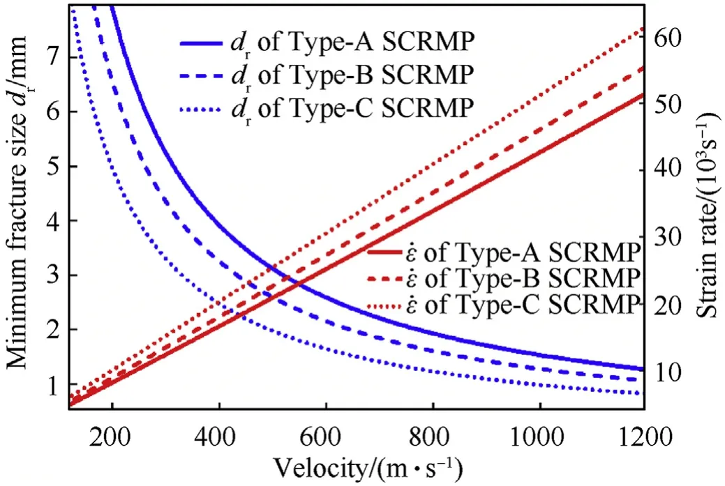
Fig.11.The relationship between fracture size and impact velocity.
Using Eqs.(4) and (18), the relationship between fracture size and impact velocity is obtained,as shown in Fig.11.As can be seen,at the same impact velocity, the fracture size of Type-C SERMP is the smallest.In particular,when its impact velocity is 1023 m/s,its minimum fracture size is 0.96 mm.This is the main reason that the average overpressure rise time of Type-C projectile is the shortest.
In addition, with the increase of impact velocity, the minimum fracture size of the reactive material decreases continuously.Therefore, for the same type of reactive material projectile, the greater the impact velocity is,the smaller the fracture size of debris is.This leads to the fact that the overpressure rise time of A,B,and C projectile is the largest at 712 m/s, 716 m/s, and 627 m/s, respectively, which is 27.8 ms, 21.6 ms, and 23.7 ms.
However,it can be seen from Table 7 that as the impact velocity increases,the overpressure rise time is not strictly in a monotonous decrease.On the one hand,this is because when the impact velocity changes in the range of 600-1000 m/s, the fracture size of the reactive materials decreases, but to a lesser extent, so the overpressure rise time does not decrease significantly.On the other hand, judging the deflagration reaction rate by the fracture size of the reactive materials is only one of the main factors.However,with the change of impact velocity, the reaction extent of the reactive material would also change,and factors such as shear ignition and deflagration diffusion process at different velocities would also have different degrees of influence on the overpressure rise time.
Additionally,it is noted from Fig.10 that the reaction length ratio of the reactive material in Experiment 13# and 4# is 1.21, and the total energy of Type-C projectile is lower than that of Type-A.However, the average overpressure ratio measured in Experiment 13#and 4#is higher than 1.21.Thus,the effect of the fracture size of reactive material on the peak overpressure is a non-negligible fact,inspired by Fig.6 that the violent deflagration of the reactive material debris cloud is mainly responsible for the pressure rise to the peak in the second stage.Fig.11 shows that the fracture size of the C-type projectile is smaller than that of the A-type projectile at the same impact velocity.In particular,the fracture size of the reactive material in experiment 13#is 0.69 times that in 4#,the finer debris cloud in a better mixing results in a higher deflagration reaction rate, making the venting effect more insignificant and ultimately leading to a relatively higher overpressure in the test chamber.
5.Conclusions
In the present work, ballistic impact and sealed chamber tests were performed on SERMP with different densities to understand the behind-plate overpressure effect when impacting the thin aluminum plates, and influences of reactive material density and impact velocity on the behind-plate overpressure effect are analyzed.
(a) The SERMP is initiated to deflagrate after penetrating the thin aluminum target,forming a behind-target overpressure area.In particular,for SERMP of a density of 7.58 g/cmwith a size of ∅13 × 11 mm, the maximum overpressure of 0.274 MPa can be generated in a test chamber of a volume of 26.5 L when it impacts a 3 mm aluminum front target at a velocity of 1023 m/s.The chemical energy released by SERMP is 1.7 times of the overall kinetic energy of SERMP and 4.1 times of the kinetic energy of the internal reactive materials。
(b) During the impact of SERMP, there is the transmission and reflection of shock waves.The shock wave transmission coefficient between the reactive material and the shell increases as the density of the reactive material increases,which is beneficial to increase the reaction extent of the reactive material, thereby forming a higher behind-plate overpressure.
(c) Unlike the bare reactive material projectile, the steel shell changes the chasing and unloading relationship between compression wave and rarefaction wave, which causes SERMP to have an overpressure limit velocity in the process of impacting thin aluminum target.For Type-A, B, and C SERMP,the overpressure limit velocities are 905 m/s,955 m/s, and 1040 m/s, respectively.
(d) The SERMP with higher reactive material density has a higher strain rate under the same impact velocity, resulting in a smaller fracture size and faster deflagration reaction rate,which reduces the overpressure rise time and is often conducive to the further increase of the overpressure.
The authors declare that they have no known competing financial interests or personal relationships that could have appeared to influence the work reported in this paper.
This work was supported by National Natural Science Foundation of China, grant number U1730112.
杂志排行
Defence Technology的其它文章
- Numerical damage evaluation of perforated steel columns subjected to blast loading
- Effect of hydrogen-storage pressure on the detonation characteristics of emulsion explosives sensitized by glass microballoons
- Blast responses of polyurea retrofitted utility tunnel reinforced with basalt fibre reinforced polymer bars
- Experimental study on the accumulative effect of multiple pulses on acceleration sensor
- Higher-order electroelastic modelling of piezoelectric cylindrical nanoshell on elastic matrix
- An improved LuGre model for calculating static steering torque of rubber tracked chassis
