Numerical damage evaluation of perforated steel columns subjected to blast loading
2022-05-24MahmoudNawarIbrahimArafaOsamaElhosseiny
Mahmoud T.Nawar, Ibrahim T.Arafa, Osama M.Elhosseiny
Structural Engineering Department, Zagazig University, Zagazig, 44519, Egypt
Keywords:Perforated steel columns Blast load Damage criterion Numerical modeling Explicit finite element analysis Web-opening shapes
ABSTRACT The structural performance of perforated steel columns(PSCs)is significantly more complex than the one of solid web I-shaped elements under the diversity of blast loading scenarios.The damage criterion of PSCs is not only related to initial deformation response during the blast but also the residual axial load capacity and it can be considered as a reliable index after the blast effects.Therefore, the PSCs damages will be studied in two stages;direct and post blast effects.In the present study,the dynamic response of PSCs was numerically evaluated under different levels of blast threats using LS-DYNA software.Extensive explicit finite element(FE)analyses are carried out to investigate the effect of various parameters,such as web opening shapes,boundary conditions and strengthening details on the damage index and toughness of the PSCs compared to the parent steel sections.The results of the comparative study show that the damage and toughness decrease when the support condition changes from pinned to fixed ends through the two stages of loadings.PSCs give high toughness compared to its parent sections during blast shock stage while, a remarkable decrease in toughness is observed during the application of axial gravity after blast shock.Furthermore, the web opening shapes have slight effects on the global dynamic behavior of PSCs,particularly in terms of residual capacity.On the contrary,the retrofitting strategy using both closed holes at end and vertical stiffeners have an effective enhancement to get higher toughness in case of the extreme blasts.
1.Introduction
The danger of explosions and terroristic threats may put the light structural element at risk more than massive structures.These terroristic accidental shocks cause unconfined surface explosions outside the buildings.Steel columns play an important role in either promoting or decreasing the damages of steel structures because the failure of an individual column element could possibly cause a progressive collapse of the entire frame structure.The use of perforated steel columns(PSCs)has been increased due to their economic and aesthetic advantages because they are produced from steel I-sections, and their webs are cut and rewelded to generate higher section depth with regular web openings shapes along their length.PSCs are significantly more complex in their structural behavior than solid Web I components.In the perforated section many new failure modes would occur, including the Vierendeel mechanism failure,web-post buckling failure as well as the shear rupture of weld in the web-post.The blast pressure starts with an instantaneous rise to the peak positive pressure and reduces gradually by exponential function to the negative phase.Also,many graphs, empirical formulas and software programs such as AT-Blast and ConWep based on the scaled distance,determined the peak reflected pressure () and the equivalent duration ().The scaled distance()was suggested by Hopkinson[1]as shown in Eq.(1):

whereis the stand-off distance (m) andis the equivalent charge weight(kg of TNT).Fig.1 shows the exterior explosion near the structure which produces the reflective pressure when the blast wave reflects on any obstacle that has an angle with the path of wave travel.
The behavior of the PSCs is highlighted since they are considered as main components of most buildings to sustain ordinary gravity loads and exceptional loads like explosion shocks.Therefore, the post-blast residual axial capacity becomes an important field of research to understand the damage sustained by PSC element and the residual axial capacity to be able to determine if a progressive collapse of the entire structure could ensue.

Fig.1.Exterior explosion near structure.
Several research studies in the literature have focused on understanding the dynamic response of reinforced concrete and steel structures without openings to blast loading,both theoretically and experimentally.Shi and Stewart [2,3] investigated a reliability analysis using the Monte Carlo Simulation (MCS) method and FE analysis for each RC columns and slabs separately.Most steel research programs have investigated the response of solid steel columns without opening.Lee et al.[4] modelled the complex interaction between the blast wave and the wide-flange steel column based on Computational Fluid Dynamics (CFD) technique using FE analyses.The effect of blast on the load bearing capacity of Ishaped columns, also was studied using various parameters (the shape of the detonation,the initiation point location,the explosive mass)at Mazurkiewicz et al.[5].The non-linear dynamic analysis of steel beam-column elements under blast was performed based on non-discretization numerical methodology at Heidarpour and Bradford[6].Nassr et al.[7-10]carried out many field experiments on steel beams and columns and validated the results of a nonlinear dynamic analysis based on a single degree-of-freedom (SDOF)model with test results.Magallanes e t al[11].also conducted a field test to investigate the behavior of a W360×347 steel column with a clear height of 5.73 m subjected to 1818 kg of TNT with stand-off distance of 4.75 m.Hadianfard et al.[12] studied the influence of steel columns cross-sectional properties and boundary conditions on their behaviors when exhibited by various blast loadings.Moreover, many theoretical research have been published to characterize the SDOF analysis of the steel column subjected to blasting loads.Shope [13] developed a simplified analytical methods for a steel column under blast load and static axial compressive force.Nassr et al.[9]had also investigated the effect of P-δ and strain rate using SDOF analysis on the column’s strength and its dynamic response under blast loads.Al-Thairy [14] presented a modified approach to the SDOF analysis method of steel columns under blast load.
Although the literature of theoretical studies generally presented an appropriate tool for design, Three-dimensional analysis using Finite Element (FE) software programs (i.e., LS-DYNA [15],ABAQUS[16],ANSYS[17],etc.)can predict the dynamic behavior of PSCs accurately, including local and global deformations under blast.Furthermore, the numerical simulations offer alternative to cost/time expensive experiments.
PSCs were studied only statically to present analytical solution for calculating the buckling resistance of axially loaded PSCs[18,19].Also, perforated cruciform steel columns were investigated numerically under axial and lateral cyclic loading [20].However,there are large studies of researchers on solid steel element through damage evaluation based on numerical studies and experimental results,the responses of steel columns with perforated web are not investigated to sustain large deformations as normally expected in blast design.Also, there was no work found on the effect of web opening shapes,boundary conditions,and strengthening details to enhance the strength and toughness of PSCs which are relatively controlled by the failure under blast load.
In this paper,the objective is to establish numerical models of a series of perforated steel columns using LS-DYNA software.Explicit FE analysis is performed and highlighted on the blast performance and toughness of PSCs compared to parent steel sections.To estimate different damage levels of PSCs, the residual axial loadbearing capacity is determined.Before performing the parametric investigation, a convergence study was carried out to validate the accuracy of FE models that are made of solid and shell elements with field test results.Extensive parametric studies will investigate the effect of web opening shapes, boundary conditions and strengthening details under various blast scenarios.The results obtained from the residual capacities are used to get the toughness of PSCs that are considered an important key in comparisons among the studied cases.
2.Finite element numerical approach
2.1.Material, elements, geometry and boundary conditions
The development of computer technology and computational mechanics helps to utilize the numerical techniques in simulation of structure response and damages when exposed to blast loads.In this paper,the hydro code LS-DYNA software[21] performs highly non-linear dynamic analyses to study the blast-induced dynamic behaviour of PSCs.MAT_PELASTIC_KINEMATIC(MAT_003)material command was used to define the steel properties including strain rate effects.It is suitable for modelling the kinematic hardening plasticity materials.Both of strain hardening and the high strain rate effect are involved in the dynamic increase factor[22,23]based on Cooper-Simonds relationship [24], that is:

where DIF is the dynamic increase factor and ε˙is the material strain rate,Theandis constant coefficients were set equal to 40.4 and 5, respectively, as suggested in Refs.[24,25].
The choice of type and size of element controls the accuracy of results and computational time.FE models of PSCs can be carried out using shell and solid elements.In the validation study, a convergence investigation was analysed by considering two different elements for each tested configuration to enhance the level of accuracy.In the shell models, quadrilateral elements with five or three integration points(“ELFORM=16”option)through the thickness of each element[26]were simulated a variety of damages in the case of large deformations and strains.In the case of solid models, eight-node brick elements were used with a fully integrated solid formulation (“ELFORM = 2” option) through the element surface [27].
Generally, the columns are exposed lateral blast load along the columns’height as well as compressive load with axially at the top end of each column.Therefore,two rigid plates are provided on the top and bottom of the column to apply axial loading and also to define fixed and pinned boundaries in the shell and solid model assemblies.Pinned boundary ends are simulated as line nodes along the plate width which their transitions are constrained and their rotations are released.While,fixed boundary ends are defined in nodes at the locations of the predicted bolts, which their rotations and translations are constrained.Fig.2 (a) and (b) demonstrate the modelling of pinned end conditions about of both strong and weak axes respectively.Fig.2 (c) illustrates the modelling of fixed end conditions.
However, the effect of boundary conditions on the buckling capacity of castellated columns due to shear and flexural deformations was studied in previous researches such as in El-sawy[19].Other studies have been statically based on the effect of perforated web shapes which vary among hexagonal hole, sinusoidal hole,circular hole,or elongated circular hole in Nawar et al.[34].So, it is a must to study the influence of web opening shapes on load bearing capacity under blast load since a little attention has been paid to PSCs.Fig.3 describes a schematic representation for the simulated columns exposed to the blast pressure,with different four web opening shapes (Hexagonal, circular, sinusoidal and,elongated circular hole shapes), with pinned and fixed conditions respectively.
2.2.Residual capacities
To obtain the full capacity of the columns, quasi-static loads should be performed to simulate the residual stresses.In perforated steel column,blast load occurs instantly then axial gravity loads are applied gradually until increasing residual axial-bearing capacity.Fig.4 shows the analysis technique which will be continued until node velocities reach to low values(<0.1 m/s)and the gravity load was then progressively increased, up to collapse.
The multi-stage numerical strategy is performed to predict the residual capacity as the following stages; First stage, quasi-static application of the primary gravity load, equal to 20% the axial capacity of the PSCs as illustrated in Refs.[2,28],within an arrival time of 50 m s[29].Secondly,application of the lateral blast pressure to the PSCs.Third stage comes when propagation of the dynamic analysis after the explosion occurred, until vibrations are damped and all nodal velocities are low enough(<0.1 m/s).Finally,gradual increase of the gravity load(axial load for the column)was applied until the column fails.At this stage, the maximum axial load is considered as the residual axial bearing capacity of the perforated steel columns[30].To ensure that the loading is quasi-static test in first and fourth stages,the strain rates were captured for all column models and it was found that their values were less than 10swhich fall in the quasi static strain rates according to the approximate ranges of the expected strain rates for different loading conditions [31].
2.3.Failure and damage criteria of PSCs
Traditionally,the amount of damage under blast pressure can be predicted by determining the support rotations and ductility ratio.The expected support rotations (θ) are calculated based on the maximum mid-displacement) and the length ()of the structural elements[32,33].The ductility ratio(μ)is defined as the ratio of the maximum deflection to the elastic deflection.UFC provisions [32] give the damage level for primary steel frame members(without/with significant compression)based on support rotation and ductility ratio.
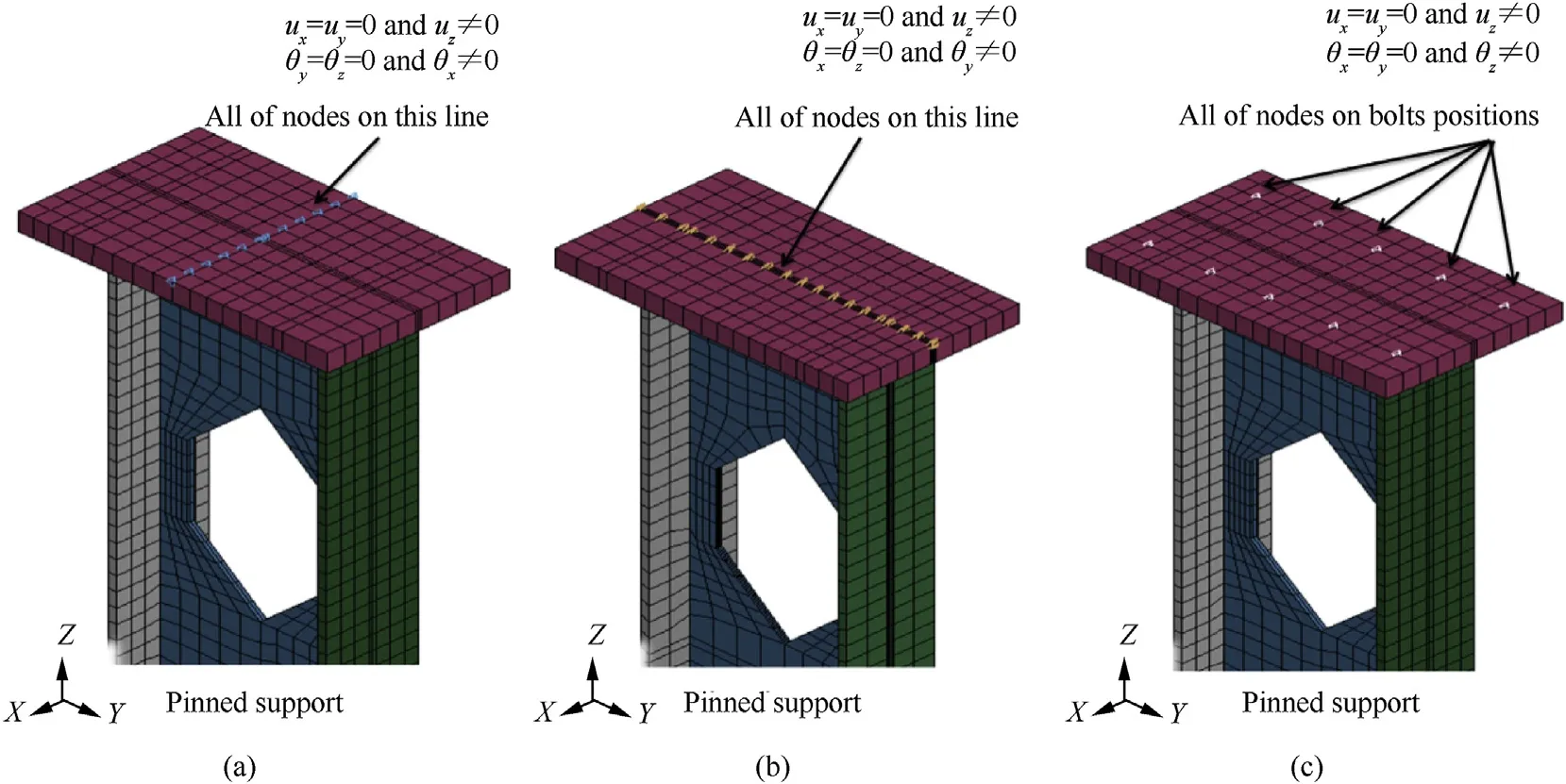
Fig.2.FE modelling of pinned and fixed support conditions of steel columns.
The damage due to blast increases when gravity loads are applied on the column.So that the criteria of ductility ratio and limits of the support rotation may not be appropriate for the estimation of local damage (especially in web buckling) for PSCs after explosion[28].Therefore,another criterion is needed to determine the damage index () which is based on the residual axial load capacity as in the following Eq.(4).
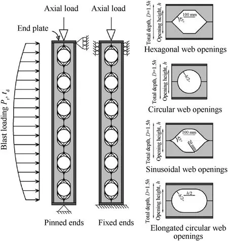
Fig.3.a schematic representation for the simulated PSCs.
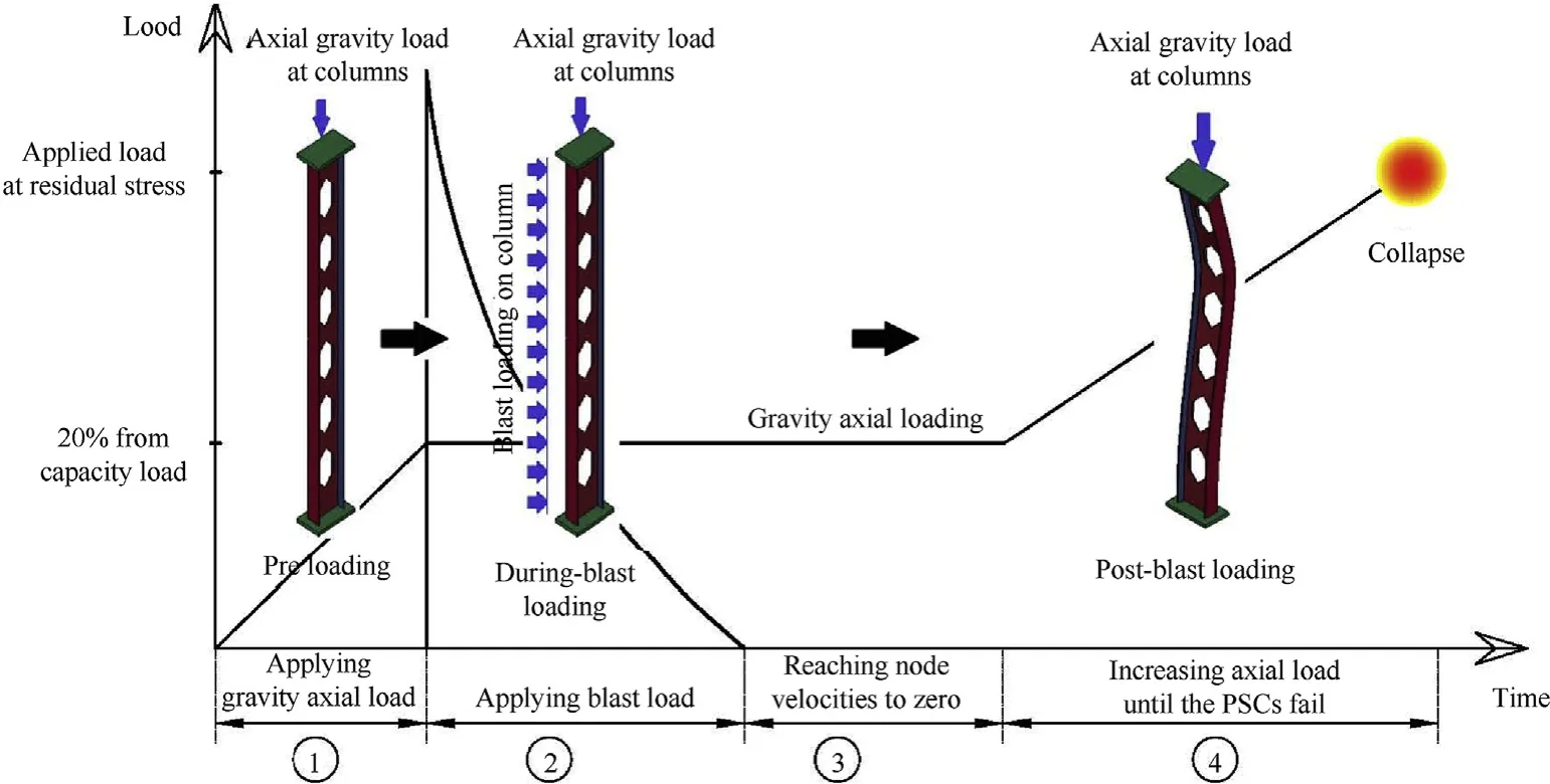
Fig.4.Schematic mechanism of the loading technique for the evaluation of the post-blast residual capacity of the examined steel columns.

whereis the maximum axial load-carrying capacity of the undamaged column,andis the residual axial load capacity of the damaged column after the explosion.Each of,values are obtained from FE analyses.
The levels of damage are classified into four levels according to their damage index [28].Low damage is the first level of damage and it occurs when the damage index is within range(=0-0.2),then the range(=0.2-0.5)is determined as medium damage,the high damage occurs when the range reaches to(=0.5-0.8),and the collapse will occur at (= 0.8-1).The analysis duration is extremely time-consuming which is controlled by means of CONTROL_TERMINATION card in LSDYNA model.To decrease the time costs as much as possible,the nodal velocities are diminished to an acceptable level by an additional damping(20%)at the time interval 150-500 ms during the third stage of loading.Therefore, that damping reduces the analysis time duration and speeds up the simulation without any effects on the residual axial capacity.
2.4.Verification of the FE modelling
The present work is an extension to Nassr et al.work[10]which depends on existing of sheathing at right and left of the column member so, there is no direct interaction through the holes of the column.Also,this assumption is suitable to simulate the real case of blast pressure on the steel buildings which contain architecture envelope.In this section, the sensitivity of FE models predictions were discussed to confirm the accuracy of the modelling, and results are compared to previous experimental results of Nassr et al.[10].To make a validation of steel column models, three experimental specimens were chosen from three explosion shots.As obtained from three tested specimens with section type W24×15,nominal length of 2.413 m and 270 kN of axial load was utilized.In both of test 1 and test 3,the columns were subjected to 50 kg and 100 kg,respectively explosive charge mass of ANFO with the same stand-off distance of 10.3 m, while the columns were subjected to 150 kg explosive charge at a distance of 9 m in test 2.The explosive energy of ANFO is approximately 82% of the energy of TNT.The boundaries of the columns are modelled with pinned ends only in the validation study.The blast loads are distributed nonuniformly throughout the column length.Bending due to the blast load was about strong axis in tests 1, 3 while the orientation of specimens was faced to weak axis in test 2.In the experimental steel samples,the material properties are a density of 7850 kg/mand its yield strength, elastic modulus, Poisson’s ratio and failure strain, were 470 MPa, 210 GPa 0.3 and 0.2, respectively.
For Test 1,2,and 3,the averages of the measured peak reflected pressures recorded by transducers used in the experiments were 307, 623, and 1560 kPa, respectively.While, the positive phase durations had an average value of 7.3,6.0,6.2 ms,respectively.Both reflected pressure and positive phase duration values can be achieved by software CONWEP to define the blast loading history in the FE models.
In the present study,a function named LOAD BLAST_ENHANCED is selected in LSDYNA to model the blast load using CONWEP data that is determined by the empirical relationships obtained from the blasting tests after fitting the data points with high-order polynomial.This function eliminates the shock wave propagation to reduce the computational time.In addition, assigning of a shockfront surface on the upper flange is used by LOAD_BLAST_ SEGMENT_SET command to simulate the interaction of blast wave with the steel beam.The columns are modelled using both of solid elements and shell elements to study the effects of element types and dimensions on accuracy of validation results.Preliminary numerical convergence studies are performed for one of the verified columns(2C)using different sizes of 10,15,and 20 mm.The max midspan displacements were 54.89 mm, 54.68 mm and 54.48 mm respectively.Consequently, the elements with dimensions of 20 mm are recommended because the obtained displacements using elements size of 10 or 15 mm are very close to the FE results of elements size 20 mm but with more computational time, Hadianfard et al.[29].Fig.5 shows the mid-span displacement time history to verify the FE models with the results of the experimental specimens for the steel columns (1C, 2C, 3C).
The columns in test 1 and 3 experienced only elastic deformations, as no permanent deformations were observed.The column in test 2 experienced yielding and plastic deformation,particularly visible at the mid-span section.Post-blast residual deformations along the column(Test2C)are measured using a total station.The maximum permanent deflection after the blast shot for columns in test 2 is captured from FE simulation.Fig.6 shows the post-blast deflected shapes of the column in test 2 achieved from the FE model using shell and solid elements and the experiments proposed by Nassr et al.[10].
Table 1 shows detailed results of FE models (peak reflected pressures,, reflected impulse,, positive phase duration,,maximum displacement,, maximum strain, ε and maximum strain rate,and they are compared to experimental results.
The averages of the measured peak reflected pressures of three blast shots, have differences of 2%, 3%, and 16.3% respectively in shell F.E.models, While the differences were 0.7%, 0.2%, and 6.7%respectively in solid F.E.models.The averages predicted reflected impulse, based on the pressure-time profiles have differences of 8.3%, 2.2%, and 1.6% respectively in shell F.E.models, compared to the corresponding values measured by experimental tests.While the differences were about 6.6%, 2.5% and 7% respectively in solid F.E.models.Generally, the differences of estimated positive phase durations in F.E.models have a range of 2-3 msec.The comparative results also show that the differences of maximum displacement obtained from the shell FE models, were 7%, 0.5%, and 5.7% in the solid steel columns (1C, 2C and 3C) respectively.While, the maximum displacements obtained from the solid FE models, have differences of 4.2%, 1.6%, and 1.2% respectively, compared to the experiment.
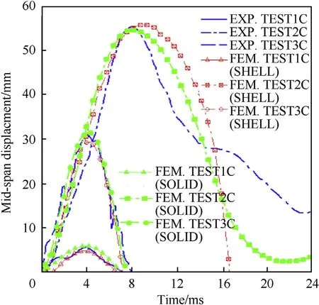
Fig.5.Mid-span columns displacement time histories achieved from FE and experiments [10].
However,there is a slight difference between experimental data and predictive finite element values, the present FE solid models give a satisfactory computational efficiency compared to shell models.Accordingly, fully integrated solid elements with eight integration points on the element surface will be recommended in the FE models to predict the behaviour of FSCs response to blast loads.
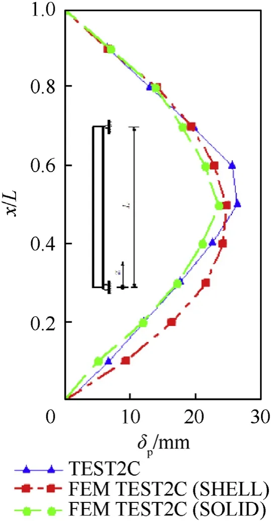
Fig.6.Permanent deflected shape of steel column (test2C) achieved from FE and experiments [10].
3.Simulation of parametric models
3.1.Geometric characteristics
A wide set of parametric FE simulations for PSCs was numerically investigated.The PSCs were created by cutting and rewelding the standard I section (W24 × 15) to form perforated web section with different opening shapes such as: hexagonal, circular, sinusoidal or elongated circular openings.Additionally, strengthening details were varied among these techniques; closed holes, vertical stiffeners, and spacer plate as shown in Fig.7.The geometric characteristics have the same material properties (density, yield strength, failure strain, elastic modulus and Poisson’s ratio) and nominal length of columns which are used in validation study(section2.4).Five different blast scenarios (BS) were involved,which are listed in Table 2.Accordingly,all the blast pressures(BS#1, 3, 4, and 5) were distributed on the same impact surfaces and faced to strong axis except the BS#2 which was faced to weak axis.Moreover, the perforated steel columns are also provided with pinned or fixed ends to study the influences of the boundary conditions.
It is worth mentioning that the aim of the research studies is to compare the dynamic behaviour of blast-loaded PSCs with its parent solid sections.The section depth of the perforated section() has one and half of the steel section depth () and the geometrical opening height is also equal to this depth ().The nominal length of FE models was 2.413 m which is the same member length used in validation study.In the case of members with spacer plates, the height of perforated section increased by 40 mm the Sinusoidal openings are created by adding fillet radius(= 50 mm) to hexagonal opening.Table 2 summarizes and provides a better understanding of what variable parameters are for each FE model and its corresponding cases.
3.2.Studied cases
Studied columns are characterized such that the previous parameters could be identified.Each case is defined with a unique name (Column (C)-web opening shapes-blast scenarios-boundary conditions-strengthening details) to cover all studied parameters.The web opening shapes vary among hexagonal hole(H),sinusoidal hole (S), circular hole (C), or elongated circular hole (E).The third symbol refers to the five blast scenarios (shot#1, shot#2, shot#3,shot#4,and shot#5).End conditions have boundary with pinned(P) or fixed (F) ends.The strengthening details have five suggests;Non strengthening (Ns), Vertical stiffeners at two ends (Vs),Continuous vertical stiffeners (CVs), Closed holes(Ch), or Spacer plates (Sp).For example, the label ‘C-H-1-P-Vs’ identifies that perforated steel column with hexagonal web openings, is exposed to first blast shot with pinned ends,the column is strengthened by two vertical stiffeners at ends.While original steel columns with parent section,are labeled such as the previous definition without the second term and that could be identified as illustrated in Table 3.Fig.8 illustrates three-dimensional FE models of the steel columns in LSDYNA.

Table 1 Matrix of Test Specimens and results of validation study.
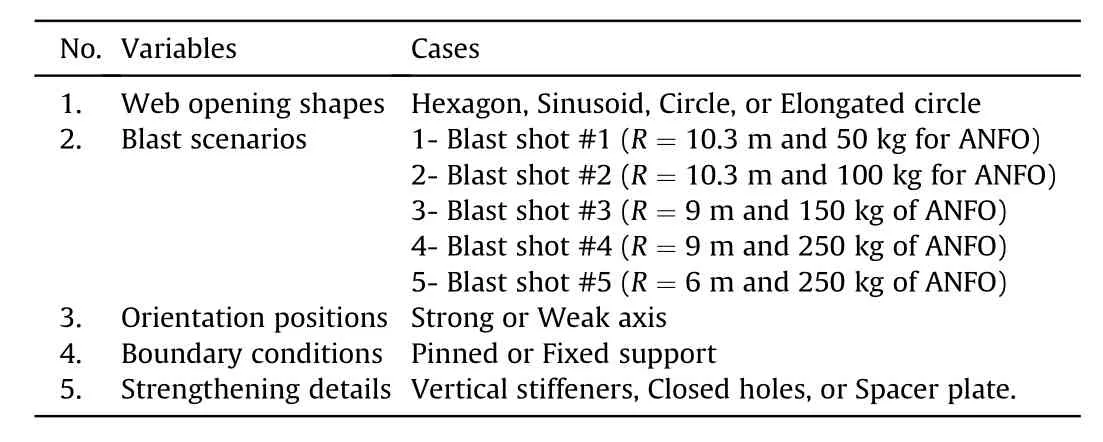
Table 2 all variables and studied cases of PSCs.
4.Numerical results and discussion
In order to evaluate the vulnerability of PSCs under different blast features, a damage index based on the residual capacity is proposed.Loading based on axial normal force are occurred after applying blast loads to capture the residual capacity of PSCs at the mid-span.Within the full set of FE dynamic simulations(up to 150 models), FE data were collected for observing the dynamic response of the examined columns under the damage scenario due to the imposed blast load pressures.The damage evaluation in columns can be estimated in accordance with Section 3.4 based on both of initial and residual capacities.
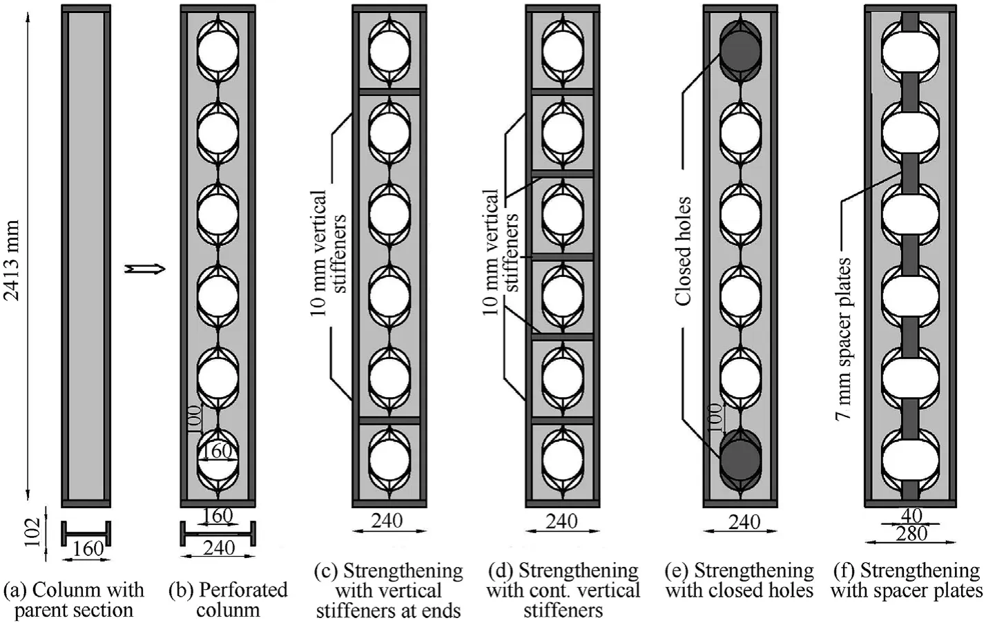
Fig.7.Geometric configuration of studied cases.
4.1.Damage evaluation of steel columns
The residual capacity () is derived from a FE analysis while,the initial capacity()can be calculated by two methods.The first one is based on equations which are presented for steel elements in AISC specifications and design guide[34,35],while the second can be estimated through FE analysis with the LS-DYNA software.In this approach, both initial and residual capacities are obtained using FE numerical method.To predict the initial capacity(), the gravity axial loads are applied gradually without blast until the column reaches its maximum capacity.The related values of the initial capacities are listed with pinned and fixed ends in Table 3.
The residual axial capacities of the steel sections were estimated to give an evidence of FE model with effects of various parameters such as types of boundary conditions and web opening shapes, as well as strengthening details under different blast features.To obtain the residual capacities of steel columns,a maximum of 20%gravity capacity was applied before shock of the blast pressure and this value was remained until the degradation of the structural response.When the nodes velocities reach to less than 0.1 m/s,the gravity load increases gradually to maximum level at which collapse mechanisms initiate and the residual capacities can be observed.Fig.9 shows the different stages of nonlinear response to obtain the residual axial capacity for columns (C-H-[1,2,3,4or5]-PNs).
Moreover,Fig.10 shows the lateral displacement time histories of two columns (C-H-2-P-Ns) and (C-H-2-P-Ns).The lateral displacements(direct and post blast)are achieved clearly in the strong shots rather than small ones where the yielding and plastic deformation can be visible.
The visual Von misses stresses of the column (C-H-5-P-Ns) are captured through the different stages of analysis in Fig.11.This figure illustrates the developments of residual axial capacity in the examined steel column(C-H-5-P-Ns)till the collapses occur at the final stage.
To better understand the differences between the damage criteria, Table 3 gives detailed results of studied steel columns in both pinned and fixed ends.The damage indices of PSCs have low damage levels compared to the results of the displacement criterion (support rotations and ductility ratio).The damage index depends on the failure modes of the steel member.The general failure modes associated with blast loading can be flexure, direct shear,local buckling.The damage index can be determined based on axial capacity () of columns because the local web buckling failure mode dominates on the structural response of the perforated and parent steel columns.
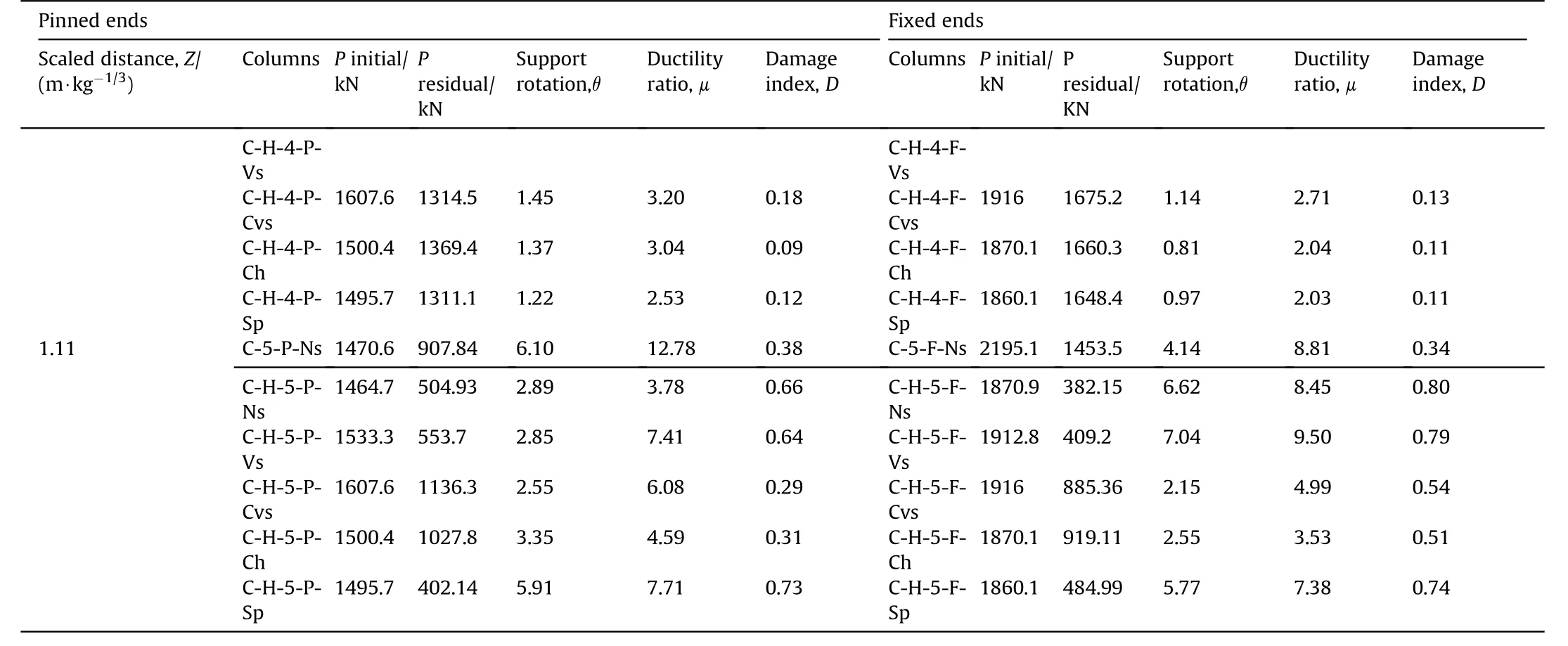
Table 3 (continued)

Table 3 Detail results of examined steel columns with pinned and fixed ends under different blast shots.
Additionally,toughness (total energy absorbed till failure)is an important indicator of PSCs for blast design.It is determined by the integration of load displacement curve till the failure point.The applied gravity loads lead to displacement indirection in the structural steel behavior.This parameter can be modified to a normalized indicator of PSCs relative to their parent steel columns to be used in the following comparative analysis.
4.2.Influence of blast scenarios
The damage levels of PSCs depend on the blast features directly.The results proved that there is vulnerability of blast pressure on the dynamic behavior and the shape of failure.The residual capacities decrease reversely with the increase of the blast pressure to emphasis the reliability of the damage indices.For the perforated steel column under weak and moderate blasts (BS#1,BS#2, BS#3,and BS#4), the failure mode was the web local buckling about the minor axis of section.While, dominated failure mode was the Vierendeel bending failure in the perforated columns under the strong blasts (BS#5) as shown in Fig.12.
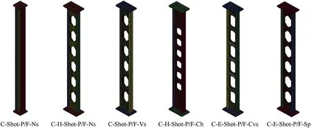
Fig.8.Finite element models of perforated columns using solid elements.
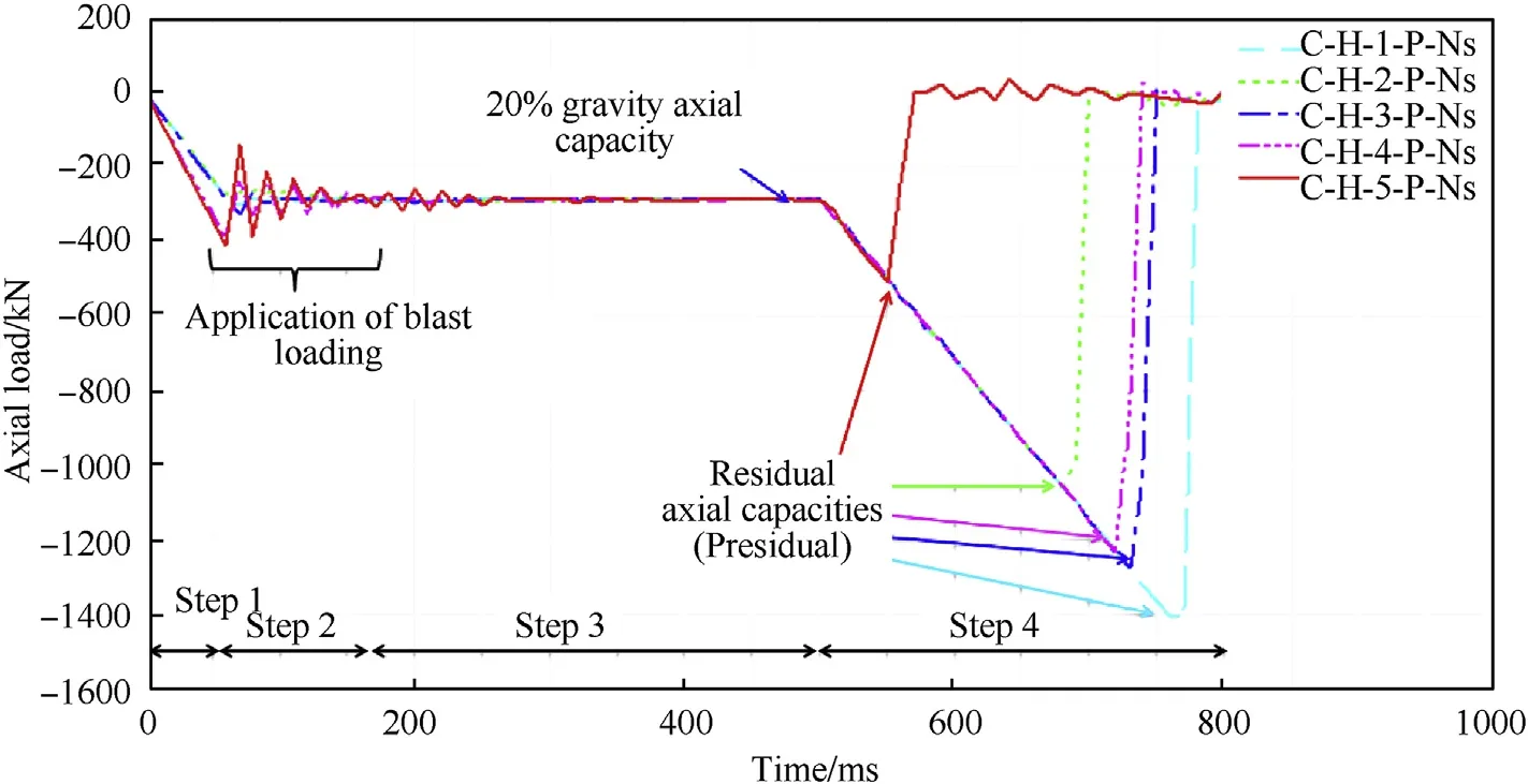
Fig.9.Axial load of perforated steel columns versus time under the different blast loadings.
The normalized toughness can clearly explain the effect of blast pressure compared to parent steel columns as shown in Fig.13.The orientation of the steel section against the blast pressure is important parameter.In the BS#2 which the blast shock was directed at the weak orientation of PSCs,the ductility capacities and support rotations of PSCs were greater than those members which were subjected to the blast shots and directed at strong orientation with convergent values of scale distance (BS#1 and BS#3).
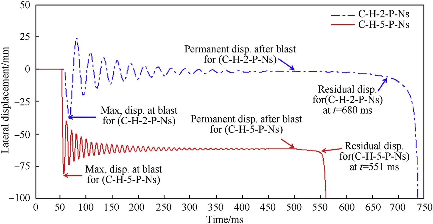
Fig.10.Lateral displacement time histories at the mid-span section.
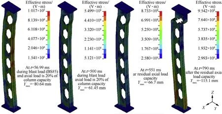
Fig.11.The developments of residual axial capacity in column (C-H-5-P-Ns) at several time instants.
However,there are significant effects of the opening web shapes and strengthening types on the dynamic response of PSCs under blasts directed at strong orientation, that effects are convergent when the blasts directed at weak orientation.The result of this is that the moment of inertia about the minor axis is not influenced by any strengthening in the web portion.
The normalized toughness can be a balanced indicator in the low and moderate blasts because it depends on the residual capacity and the maximum deformations at the same time and will be compared to parent sections.Otherwise, the comparisons depend on the residual capacities only in the extreme blasts because the damages occur in early time.
4.2.Influence of boundary shapes
In this section,the effects of boundary condition on probability of failure are investigated based on the displacement criterion(during blast effects) and the damage index criterion (at residual capacity).By changing the support conditions from pinned to fixed ends, the damages after the blast shock change from medium to low level.The columns with pinned ends permit to deform more than those with fixed ends at both states of the blast loading and residual capacity zones, because the damage is controlled by the stiffness of connections.In strong blast(BS#5),the behavior of PSCs may give a reverse result due to the sudden shear failure formed in the weak holes near the fixed connections.Additionally, the value of residual capacities increases, and the damage indices decrease when the support conditions change from pinned ends to fixed ends under the weak and moderate blasts.In contrast,the residual capacities decrease, and the damage indices increase under the strong blasts(BS#5).Therefore,the residual axial capacity criterion can predict the behavior of PSCs precisely and will present damage evaluation more accurately.
4.3.Influence of web openings
The web opening shapes can be investigated based on the ductility ratio and normalized toughness.Fig.14 demonstrates the effect of the web opening shapes (Hexagon, sinusoid, Circler,Elongated circular)on the normalized toughness of the PSCs under BS#3.The columns with sinusoidal and elongated circular web openings have a slightly higher toughness than other shapes because these shapes give a high deformation at residual capacity in the local web damages about the minor axis of section.The behavior of columns with other web opening shapes has so close toughness values.Generally,the web opening shapes have slightly effects on the blast resistance of PSCs.
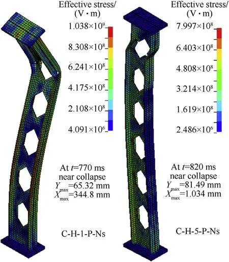
Fig.12.Von misses stresses of the columns (C-H-1-P-Ns and C-H-5-P-Ns).
4.4.Influence of strengthening details
The effectiveness of strengthening details depends on the damage mechanisms and failure modes for the PSCs.Strengthening strategies vary using different elements such as two vertical stiffeners only at ends(Vs),continuous vertical stiffeners(CVs),closed two holes at ends (Ch), and spacer plates (Sp).In this section, the effects of strengthening details on probability of failure are addressed based on the toughness compared to the PSCs without strengthening.Only strengthening by two vertical stiffeners (Vs)gave a little increase up to 10% at the fixed state and the others didn’t give any increase on the toughness.The used strengthening strategies is related to retrofit about the major inertia of the perforated section whereas, the dominated failure mode in the columns is the web local buckling about the minor axis of section.So that,strengthening details in the PSCs can be effective by using other strategies to retrofit about the minor axis.All previous results are related to the low and moderate blast scenarios in which also strengthening by closed holes gave the worst values of relative toughness because it doesn’t allow the PSCs to deform under blast loading.In strong blasts(BS#5),radical changes had taken place in the effectiveness of strengthening details whereas, retrofitting by both closed holes at end(Ch)and continuous vertical stiffener(Cvs)gave an obvious increase on the toughness because the strong strengthening helps to promote the residual capacities even though its small deformations.
5.Conclusions
In this approach, an explicit FE method to analyze the damage criterion and failure modes of perforated steel columns (PSCs)under blast loads which was validated using published test data.Extensive parametric studies are performed to investigate the effect of web opening shapes, boundary conditions and strengthening details based on the damage criteria and toughness of the PSCs compared to the parent steel sections.The comparative FE results of the present study are summarized as the followings:
• A convergence studies were carried out about mesh sensitivity to validate the accuracy of FE models with acceptable computational time.
• The validation study shows that using fully integrated solid elements in the developed FE model gives better computational efficiency compared to shell models.
• The damage indices based on the residual capacities can present damage evaluation more accurately for the PSCs, unlike UFC damage criteria, as it depends on the local damages and local failure modes under different blast scenarios.
• PSCs give high toughness compared to its parent sections during blast shock stage while,a remarkable decrease in toughness are observed during the application of axial gravity after blast shock.
• The columns with pinned ends permit to deform more than those with fixed ends at both the two stages of loadings(direct and post the blast) because the damage is controlled by the stiffness of connections that change the indeterminacy of the columns.

Fig.13.Toughness results of perforated steel column normalized to parent section results under different blast pressure.
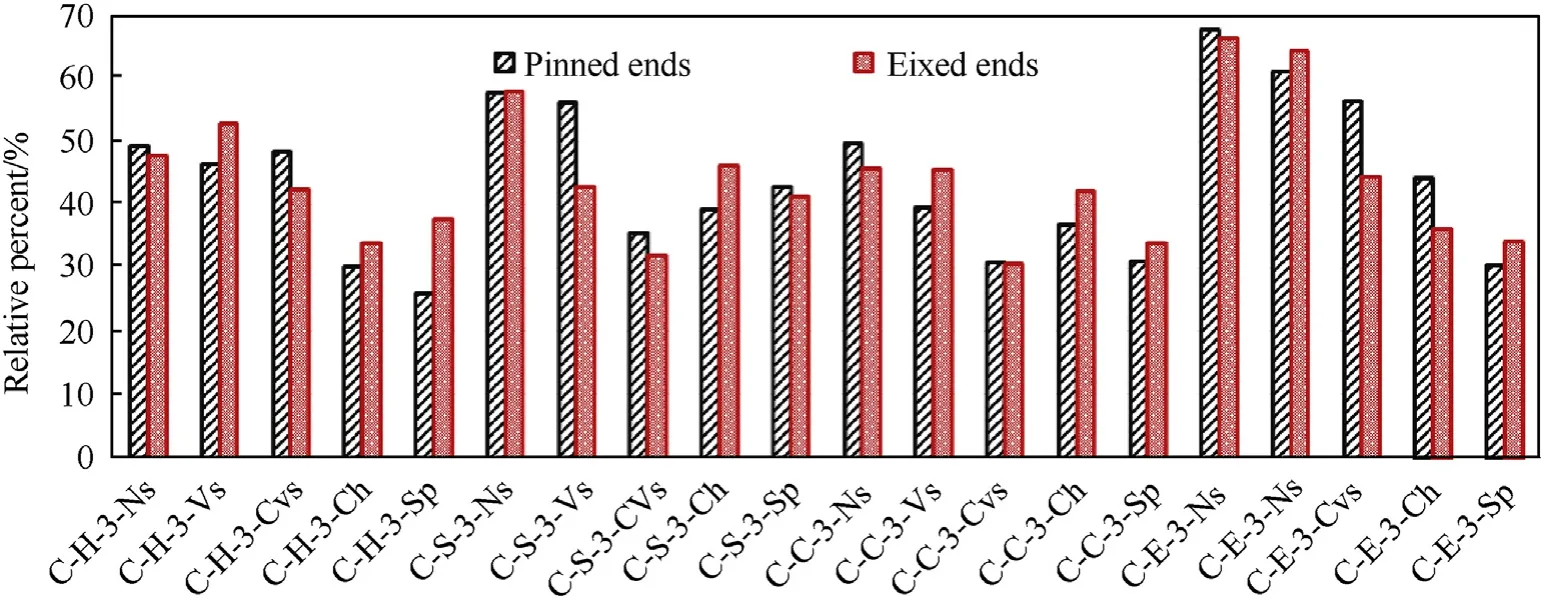
Fig.14.Normalized toughness results of perforated steel columns with different web opening shapes under BS#3.
• Under low and moderate blasts, the residual capacities are increased and the damage indices are decreased when the support conditions are changed from pinned to fixed ends.However, the behavior of PSCs gives usually reverse results under the extreme blasts.
• The web opening shapes have minor impact on the global dynamic behavior of PSCs.The columns with elongated circular web openings have a slight higher toughness than other shapes.This shape gives a high deformation at residual capacity in the local web damages about the minor axis of section.
• Under the low and moderate blasts, the strengthening by two vertical stiffeners at the ends provides higher values of the toughness for PSCs than the others at the fixed state.
• In case of the extreme blasts, the strengthening strategy using both closed holes at the ends and continuous vertical stiffeners have an effective enhancement to get higher toughness.
The authors declare that they have no known competing financial interests or personal relationships that could have appeared to influence the work reported in this paper.
杂志排行
Defence Technology的其它文章
- Defence Technology
- Roll angular rate extraction based on modified spline-kernelled chirplet transform
- Buckling of composite cylindrical shells with ovality and thickness variation subjected to hydrostatic pressure
- Preparation of the core-shell HMX@CS microparticles by biological excitation:Excellent hydrophobic-oleophilic properties and decreased impact sensitivity effectively
- Quantitative prediction and ranking of the shock sensitivity of explosives via reactive molecular dynamics simulations
- An efficient light-to-heat conversion coupling photothermal effect and exothermic chemical reaction in Au NRs/V2C MXene membranes for high-performance laser ignition
