An improved LuGre model for calculating static steering torque of rubber tracked chassis
2022-05-24KngLingQunzhngTuXinminShenZhonghngFngXunYngYongZhngHuiyuXing
Kng Ling , Qun-zhng Tu , Xin-min Shen , Zhong-hng Fng , Xun Yng ,Yong Zhng , Hui-yu Xing
aCollege of Field Engineering, Army Engineering University of PLA, Nanjing, 210007, China
bState Key Laboratory of Intelligent Manufacturing of Advanced Construction Machinery, Xuzhou Construction Machinery Group, Xuzhou, 221004, China
Keywords:Rubber track Static steering torque Friction model Chassis Maneuverability Vehicle
ABSTRACT Tire and rubber track interchangeable chassis combines the advantages of tire and rubber track, which can greatly improve the maneuverability of military construction machinery.However,there is almost no effective calculation model for the real-time static steering torque.When the relative sliding speed is greater than 0.01 m/s, the influence of friction heating can not be ignored.An improved LuGre model is established to calculate the static real-time steering torque of tire and rubber track interchangeable chassis.Firstly,the friction heating model between rubber and ground is established.Combined with the influence of temperature on the dynamic performance of rubber material, the influence of friction heating on the stiffness and friction coefficient of rubber track is analyzed, and the improved LuGre friction model is established.The steering torque of tire and rubber track interchangeable chassis is affected by rubber material properties, steering speed, pavement type, and ambient temperature.Compared with the original LuGre model, the improved LuGre model captures the change in friction torque during multiple in-situ turns due to frictional heating.The error with the experimental data is small, which verifies the effectiveness of the improved LuGre model.
1.Introduction
With the gradual increase in the rapid maneuvering speed of main battle vehicles,military construction machinery also needs to have stronger maneuverability.The tire and rubber track interchangeable chassis can effectively improve the maneuverability of military construction machinery.The tire and rubber track interchangeable chassis has two driving modes: tire driving mode and rubber track driving mode.The military vehicle can drive at high speeds on the highway through the tire driving mode.The rubbertracked vehicle has low ground pressure and can safely pass through muddy areas[1,2].The two driving modes can be switched to each other, thereby improving the maneuverability of the vehicle.Therefore,tire and rubber track interchangeable vehicle is widely used in military equipment, emergency rescue, snow operations,geological exploration,field pipeline network survey,and agricultural machinery.The steering methods of general chassis are mainly divided into cornering wheel steering and differential steering.The cornering wheel steering is usually used for wheeled chassis.The differential steering is commonly used in tracked chassis and some wheeled vehicles.However,the steering mode of tire and rubber track interchangeable chassis is the deflection track steering mode.The existing theories of cornering wheel steering and differential steering do not apply to the deflection track steering mode of a tire and rubber track interchangeable chassis.The research on the steering mode of the deflected track has not attracted enough attention [3,4].
For the steering theoretical model of the tire and rubber track interchangeable chassis, domestic and international researchers have carried out the following research.Guo H and Zhao Z et al.established the maximum steering torque model based on ground pressure distribution.The ground pressure distribution model can be expressed as the uniform ground pressure distribution or cosine ground pressure distribution model.According to the model, the static steering resistance torque of the rubber tracked chassis was calculated integrally[3,4].Besides,many scholars have studied the ground pressure distribution model and influencing factors of rubber track and ground, which provides a basis for further research on steering theory.Besides, many scholars have studied the ground pressure distribution model and influencing factors between rubber track and ground.The ground pressure distribution of the track has an important influence on the steering performance of the rubber track [5].Keller T et al.have tested the vertical stress distribution under the contact area, and compared the vertical stress and vertical soil displacement of rubber crawler tractors and wheeled tractors.A model was proposed to determine relationships between characteristics of measured stress distribution and easily measurable parameters and load[6-10].Liu W et al.established and verified the longitudinal ground pressure distribution model of the rigid and flexible composite tracked vehicle[11].The above research shows that for the tire and rubber track interchangeable chassis, the existing research results can analyze the maximum steering torque in the steering process according to the distribution of ground pressure.However, the model cannot express the real-time steering torque during the steering process,and cannot meet the needs of precise steering and electronically controlled steering.
There is almost no effective calculation model for the steering process of rubber tracks.However,some researches on the friction mechanism between rubber and the ground, dynamic friction model, and track ground pressure distribution and other related topics can be used as the basis of this research.
For the LuGre model, some researchers have conducted extensive research on basic characteristics and parameter identification.And it has been applied to establish the friction model between tire and ground.Astrom KJ et al.analyzed the properties of the LuGre model, including zero slip, invariance, passivity, and velocityrelated micro-damping.The analysis shows that the LuGre model can simulate a good transition of different friction effects [12-14].Canudas-de-Wit C et al.used the LuGre model to describe the friction characteristics between the tread and the ground under the conditions of car driving and brake lights and tested the accuracy of the model[15].The above research shows that the LuGre model can be used to describe the friction characteristics between the rubber and the ground.But, there is almost no Lugre model used in the analysis of the steering torque process of the rubber tracked chassis.
Many scholars have conducted extensive research on the friction mechanism between rubber and the ground, including the main types of friction, friction heating law, and the effect of temperature on the friction coefficient.Persson,BNJ.et al.have shown the friction between rubber and the ground mainly includes hysteresis friction and viscous friction.For rough roads,the proportion of viscous friction is relatively small [16,17].When the friction speed is greater than 0.01 m/s, the influence of friction heating cannot be ignored [18-20].The friction temperature will change the stiffness of the rubber, thereby reducing the change in viscoelastic friction properties.The effect of frictional heat generation on the stiffness of rubber materials [21,22].Considering the influence of friction heating on tire steering friction, an improved magic formula tire friction model was established to predict the steering torque process of tires [23].The analysis of microscopic friction mechanism can describe the main effects and changing trends of friction.Perhaps,the micro friction mechanism combined with the LuGre model is a good method to describe the steering process of the rubber tracked chassis.
Besides,related researchers studied the material properties and constitutive equations to improve the comprehensive performance of rubber tracks.Zhao Z et al.established a constitutive model of the rubber-cord composite material by characterizing the mechanical behavior of large-deformation, nonlinear and anisotropic rubber tracks under different working conditions[24].Yang X et al.studied the bonding properties of rubber materials and fibers to improve the mechanical properties of rubber tracks [25-28].The analysis and improvement of the properties of these materials play an important role in our improved LuGre.
Through these documents,there is almost no effective model to describe the real-time steering torque of the rubber tracked chassis.In the follow-up content of this article, the influence of frictional heating on the friction coefficient will be considered, and an improved LuGre model will be proposed.Realize the simulation of the steering torque during static real-time steering,which provides the basis for the precise steering and electronically controlled steering of the vehicle.
2.Model development
2.1.Basic LuGre friction model
As shown in the blue box of Fig.1,the original LuGre model is a simplified physical model of the bristle, which uses a first-order differential equation to express the elastic friction, micro damping friction, and macro damping friction between rubber and the ground as Eq.(1) [13,14].Among them, the elastic friction can be expressed in the form of σ; micro damping friction can be described by σ˙;macro damping friction can be expressed by σv.

whereis the friction force;is static friction force;is coulomb friction force; δis the shape factor of Stribeck curve; σis the asperity stiffness;σ、σis the damping coefficients that relate to the presliding and kinetic friction states,respectively,is the state variable interpreted as the elastic deformation of surface asperities of adjacent bodies;is the longitudinal displacement;v=d/dis the sliding velocity;vis the Stribeck’s velocity;(v)is the Stribeck’s friction.
2.2.Improved LuGre friction model
Some research data indicate that the friction between rubber and substrate is mainly composed of hysteresis friction and viscous friction.Viscous friction is caused by van der Waals forces between the rubber surface and the substrate.For smooth substrates,due to the low elastic modulus of rubber, the van der Waals force will cause almost complete contact between the rubber and the smooth interface.In this time, van der Waals force interaction dominates resulting in greater friction.However,for rough surfaces,the actual contact area between the tire and the conventional road surface is usually only about 1%of the nominal contact area.At this time,it is generally considered that the friction between the rubber and the ground is mainly hysteresis friction, and viscous friction only accounts for a small part of rubber friction[18].Therefore,the effect of viscous friction on the friction between the rubber track and the ground is ignored in the improved model as Eq.(2).

When the relative sliding velocity v<0.01m/s between the rubber and the ground,the rising temperature can be ignored due to the diffusion of heat.However,when the relative sliding velocity v ≥0.01m/s, the rising temperature caused by sliding will affect the viscoelasticity of the rubber material, thereby affecting the friction coefficient of the rubber track[19,29].Since relative sliding velocity v ≥0.01m/s in the grounding area of the rubber track,the influence caused by rising temperature during the turning process cannot be ignored.Also,the existing LuGre model cannot reflect the effect of frictional heat on the steering torque.Therefore,the effect of steering friction heating on steering torque will be discussed in detail.As shown in the red box of Fig.1, the effects of friction heating on stiffness, Coulomb friction, and static friction are integrated into the original model to obtain the improved LuGre model as Eq.(3).

Fig.1.Flowchart of the original LuGre model and improved LuGre model.

whereis the friction torque; σis the stiffness in terms of temperature;σis the damping coefficients that relate to the presliding;is the static friction torque in terms of temperature;is the Coulomb friction torque in terms of temperature;δis the shape factor of Stribeck curve,δ=2 [30];is the state variable interpreted as the elastic deformation of surface asperities of adjacent bodies;is the sliding angle velocity;is the Stribeck’s velocity;() is the Stribeck’s friction torque.
Due to the small thermal conductivity of the material, it is assumed that the friction heating only leads to the temperature rise of the track pattern.The temperature rise of the ground is ignored,which is caused by the friction between the track and the ground.All the energy consumed by the friction between the track and the ground is assumed to be transformed into the temperature rise of the rubber.According to the thermal expansion process of the contact surface,the equation of thermal diffusion is established as shown in Eq.(4).

where λ is the heat transfer coefficient;is the contact area of tread;is the thickness of the track pattern;is the real-time rubber temperature during friction;is the initial ambient temperature;ρ is the density of the material;is the heat capacity;is the time interval; Δ.is the temperature interval.
According to the conclusion of Ref.[31], the stiffness of the grounded micro-element can be expressed as a function of the elastic modulus as Eq.(5).Due to the complex structure of the track pattern, there is no effective method to determine the position of the rotation axis of each tread pattern unit.Therefore,it is difficult to calculate the moment of inertia of the rubber track.However,the above problems can be avoided by measuring the initial stiffness and the properties of track rubber materials.In the process of frictional heating,the stiffness σcan be expressed as the function of the initial stiffness σand the change ratio of the elastic modulus as Eq.(6).

whereis the excitation frequency;is the moment of inertia;(,)is the elastic modulus of rubber at excitation frequencyand temperature;(,)is the elastic modulus of rubber at excitation frequencyand temperature.
According to the WLF(--) function[18,32], the influence of temperatureon the elastic modulus(,) of the rubber can be transformed into the influence of the disturbance frequencyas Eqs.(7) and (8).The dynamic performance parameters under real-time temperature and excitation frequency can be calculated by using the curve with measured temperature or frequency as variable and dynamic performance parameters as a dependent variable.

Where

where αis the shift factor at temperature;αis the shift factor at temperature;is the reference temperature of the rubber material.
Then, Eq.(9) is obtained by combining Eq.(7) and Eq.(6).The stiffness can be expressed as a function of the initial stiffness and the change rate of elastic modulus.The change rate of elastic modulus is the ratio of elastic modulus to initial elastic modulus under temperatureand.

According to the literature [16], regardless of the influence of frictional heating,the coefficient of friction between rubber and the ground can be approximately expressed as a function of ground roughness characteristics and rubber elastic modulus,as shown in Eq.10 and 11.
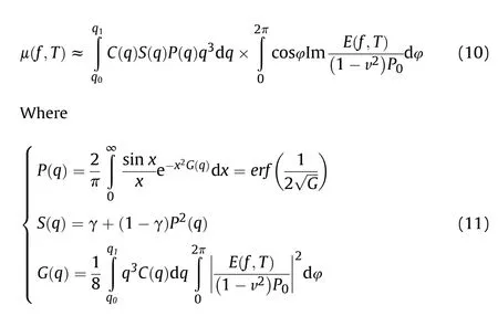
whereis the nominal contact stress;is the roughness wavevector;φ is the phase angle;()is the relative contact area;()is the surface roughness power spectrum;() is a correction factor which takes into account that the asperity induced deformations of the rubber; v is the sliding velocity.
The influence of temperature on the coefficient of friction can be characterized by the influence function of temperature on the elastic modulus of rubber.The friction coefficient can be approximately expressed as a function of pavement characteristic parameters and material properties, as shown in Eq.(12).

Where

Whereis the long distance roll-off wavevector;is the RMS roughness amplitude;μ(,)is the coefficient of friction;μ(,)is the initial friction coefficient; λis the shortest roughness wavelength component of asphalt pavement.
According to Eq.(12), the friction coefficient at the initial state and at any time is expressed as a function of ground characteristic parameters and rubber material parameters,as shown in Eq.(14).

The friction coefficient is expressed as a function of the initial friction coefficient and rubber material performance parameters,as shown in Eq.(15).

As shown in Fig.2, the rubber track assembly mainly includes the drive wheel, roller wheels, tension wheel, tension springs,tension arms,front wheel,rear wheel,and rubber track.The wheelside reducer of the axle is connected with the driving wheel by fasteners.The axle drives the driving wheels to rotate, driving the chassis to travel.At the same time,the vehicle loadis transferred to the rubber track assembly.The center of gravity of the rubber track assembly is.andare all external loads of the rubber track assembly.
The load model of the wheel train of the rubber track assembly is divided into two levels.The first stage balance gear train realizes the load distribution of the rubber track assembly to the balance shaft.The second-level balance gear train realizes the load distribution of the roller wheels.
As shown in Fig.2(a), the load-bearing model of the first-stage balance gear train can be expressed as Eq.16 and 17.

whereis the axle load;is the weight of the rubber track assembly;is the load of the first balance shaft;is the load of the second balance shaft;is the horizontal distances betweenand;is the horizontal distances betweenand;is the horizontal distances betweenand;is the horizontal distances betweenand;αis the balanced ratio ofto(+);αis the balanced ratio ofto(+).The range of αand αis 0-1.

Fig.2.Wheel system layout and load of the rubber track assembly.
The load model of the second-stage wheel train is shown in Eqs.(18) and (19).

whereandare loads of roller wheels 1-4 in sequence.is the horizontal distances betweenand;is the horizontal distances betweenand;is the horizontal distances betweenand;are the horizontal distances betweenand; βis the balanced ratio ofto (+) ; βis the balanced ratio ofto(+) .The range of βand βis 0-1.
Therefore,the load model of the rubber track assembly is shown in Eq.(20).

As shown in Fig.2(b), it is a top view of the rubber track grounding area.Taking the steering hinge point as the coordinate origin, the track traveling direction is theaxis, and the lateral direction is theaxis,a plane coordinate system is established.Theandcoordinates of the center point of the roller wheels are shown in Eqs.(21) and (22).


Among them,,,andare theaxis coordinates of the center point of the roller wheels respectively;,,,are theaxis coordinates of the center point of the roller wheels;is the width of the rubber track;is the distance between the inner side of the track and the steering hinge point.
The ground pressure distribution law of rubber track on soft soil and hard soil is basically similar.In addition, the same mathematical model and different parameter values can be used to describe the ground pressure distribution of rubber tracks on hard or soft ground [4].The distribution of vertical stress in the longitudinal direction under the roller wheel was described by harmonic oscillation.The distribution of vertical stress in the lateral direction was modeled as a linear function with the maximum stress at the centerline of the track and the minimum at the edge of the track[6].The ground pressure distributionof the i-th roller wheel of the rubber track assembly can be expressed as shown in Eq.(23).Therefore, the model of Eq.(23) with different values of the variablesand Lcan represent the ground pressure distribution of the rubber track on hard or soft ground.The value range ofis 2-4.Among them,on hard ground,the value ofapproaches 4.On soft ground,the value ofapproaches 2 [4,6].

where the value ofis 3;is the maximum vertical stress under the i-th roller wheel;Lis the dynamic contact length of the wheel, the value ofis obtained by iterative solution of programming loop;and the range ofis between-/2 and/2;the range ofis between -/2 and/2.Thefunction is symmetrical concerning the centerline of the track.
The ground pressure distribution of the rubber track can be discrete into the ground pressure distribution combination of roller wheels.Furthermore, the steering torque generated by the rubber track assembly can be discretized into the steering torque generated by each roller wheel.The distribution of steering torque produced by each roller wheel is shown in Fig.3.The steering torque generated by the roller wheels reaches the peak value of the steering torque at the center point of the roller wheels.Therefore,the steering torqueandgenerated by the i-th roller wheel is expressed as the friction torque generated by the roller wheel loadacting on the center point (,)of the axle.
The steering torque of the rubber track assembly,which can be expressed as the sum of the steering torques generated byroller wheels in Eq.(24).
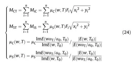
where Mis the i-th Coulomb steering torque calculated according to the roller wheel layout;is the coulomb the steering torque of the rubber track assembly calculated according to the roller wheel layout.Mis the i-th static steering torque calculated according to the roller wheel layout;μ(,)is the Coulomb friction coefficient;μis the initial Coulomb friction coefficient; μ(,) is the static friction coefficient;μis the initial static friction coefficient;is the static steering torque of the rubber track assembly calculated according to the roller wheel layout.
fi
The parameter σrepresents the damping in the pre-sliding state.The influence of the parameter σon the model’s ability to accurately simulate friction depends on the application scenario.For precision systems at the micron and nanometer scale,σis a key parameter.However, in the mechanical system within the millimeter level,the influence of the micro damping coefficient is small[13].Its main function is to stabilize the integration process of the friction model equation.Therefore, the micro damping coefficient can be as shown in Eqs.(25) and (26).
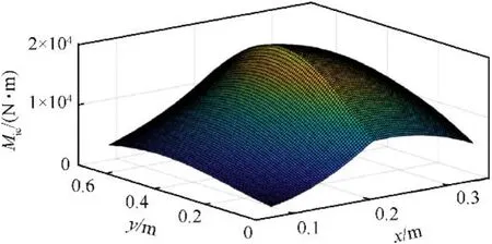
Fig.3.Distribution diagram of Mic.

Then

where τ is the unitary damping;is the natural frequency;is the moment of inertia; ξ is the dimensionless relative damping with the typical choice of ξ=0.5 [13].
In the static steering process, the steering torque includes the steering torque generated by friction torque and the aligning moment, as shown in Eq.(27).

Whereis the steering torque;is the aligning moment.
According to the Reimpell model,there are vertical force,lateral force, and longitudinal force in the track contact surface.These three forces produce the aligning moment that causes the steering system to return to the center after cornering.The aligning moment can be expressed as a function of the handling load, kingpin inclination angle,steering angle,and vertical arm of force,as shown in Eq.(28).

Where θis the kingpin inclination angle;θis the steering angle;is the lever arm.
3.Research objects and methods
3.1.Experimental platform and test system
The Multifunctional special vehicle is equipped with a 4×4 allwheel-drive tire and rubber track interchangeable chassis.As shown in Fig.4,the chassis has tire driving mode and rubber track driving mode.When the rubber track driving mode is adopted,the reflection track steering mode is adopted.The steering angle of the left and right wheels conforms to the Ackerman angle law.
The steering system of the chassis includes the main steering system and auxiliary steering system.The main steering system can provide sufficient steering torque for the tire driving chassis.During the steering process using the main steering system,hydraulic cylinder 1 and the hydraulic cylinder 2 jointly drive the steering system of the chassis.By adjusting the operating panel of the cab,the tire steering mode can be switched to rubber track steering mode.The main steering system and the auxiliary steering system work together to meet the steering torque of the rubber track driving mode.When the main and auxiliary steering systems are used at the same time, the hydraulic cylinder 1, the hydraulic cylinder 2, the hydraulic cylinder 3, and the hydraulic cylinder 4 jointly drive the steering system of the chassis.The details and schematic diagram of the steering system are shown in Fig.5.Besides,to reduce the impact load when the steering cylinder reaches the limit position,elastic limit devices are installed at both ends of the steering cylinder.

Fig.4.Multifunctional special vehicle.

Fig.5.Main steering system and auxiliary steering system.
This rubber track assembly provides the vehicle with highspeed driving ability.It is mainly used as a rubber track drive system for utility vehicles.The system can improve the maneuverability of the utility vehicle so that the utility vehicle can quickly reach the workspace to carry out operations.
As shown in Fig.6,the rubber track assembly includes a driving wheel, tension wheel, roller wheels, tension arm, and tension spring.The driving wheels are located on top of the triangle track.The driving wheel is connected to the wheel-side reducer driving the axle.The driving wheel drives the rubber track through driving teeth.The tension wheel is located at the front of the rubber track assembly,and the tension arm and tension elastic device is used to tension the rubber track.The lower part of the rubber track assembly includes two sets of equal load wheels.The diameter of the middle group of wheels is the same.The diameters of the load wheels of the latter group are different.

Fig.6.Rubber tracked assembly.

Fig.7.The experimental data acquisition system.
As shown in Fig.7, the test system is mainly composed of a laptop computer, data acquisition software, data acquisition instrument, hydraulic pressure sensors, and rotation angle sensors.The specifications and models of the data acquisition system are shown in Table 1.
3.2.Methods and parameters
The steering torque of the vehicle is difficult to measure directly.Therefore,we test the oil pressure of the steering cylinder and the steering angle of the right front rubber track assembly.Through the steering hydraulic pressure and steering angle,the steering torque of the tire-rubber track interchangeable vehicle can be calculated.The improved LuGre model and the original LuGre model are simulated by open-source data analysis software python.The version of Python is 3.8.
In 1987, the road surface was divided into Micro-texture(λ<0.5mm), Macro-texture (0.5<λ<50mm), Mega-texture(50<λ<500mm) and unevenness (λ>500mm)) By the Permanent International Association of Road Congresses (PIARC).According to Ref.[33], the surface texture of the road surface will affect the interaction of the road surface and the rubber track.The friction between rubber and the ground is mainly affected by micro-texture and macro-texture.Micro-texture mainly affects adhesion friction.Macro-texture affects the hysteresis friction component.Because we mainly discuss the effect of viscous friction in this paper, we focus on the analysis of the effect of Macrotexture.Therefore,the value of the wavelength we selected is λ≈0.01m [18].
In this article,the test road condition is a dry concrete road.The road is intact and undamaged.The slope of the road does not exceed 1%.Both the steering stiffness test and the continuous steering test are performed on the same road surface as mentioned above.
According to Ref.[34], the initial static friction coefficient and Coulomb friction coefficient of different roads are shown in Table 2.Note that the road surface discussed in this article is a solid hard road.The steering torque on softer roads mainly comes from the shear force of the soil, which is beyond the scope of this article.
The parameters of theoretical analysis are shown in Table 3.

Table 1 The experimental data acquisition system parameters.

Table 2 Friction coefficient of pavements.

Table 3 Parameters of theoretical analysis.
According to the theoretical analysis in the second chapter above, to complete the LuGre model simulation analysis, it is necessary to test and analyze the steering stiffness σ.According to the test method of reference [14], the identification method of static friction stiffness is developed.Only the main steering system shown in Fig.5 is operated.As shown in Fig.8(c).,the steering loadis slowly applied to the front wheel steering system.After reaching the maximum load, the load remains above 10S.At this time, the rubber tracked chassis does not turn, but the steering angle will change slightly.The sum of the steering angles of the left and right track isθ.Due to the small steering angle, the steering angle error caused by Ackerman steering is ignored.The value σ=/θ is obtained as 5393.7 Nm/.
The input of this paper is the real-time curve of the left and right rubber track steering angles.During the in-situ steering experiment, the test system in Fig.6 was used to test and record the steering angle of the left and right rubber track.The recorded data is shown in Fig.8(a).The solid black line indicates the steering angle of the left track.The red dotted line indicates the steering angle of the right track.The turning process can be divided into 15 stages,namely ta-tb,tb-tc,…to-tp.In the interval of tc-td-te,tf-tgth, ti-tj-tk and tl-tm-tn in Fig.9, the steering angle gradually approaches the limit angle and remains stable.At this time,the stroke of the steering cylinder is close to the displacement limit of the cylinder.The elastic limit device of the steering cylinder begins to generate a reverse torque.At this time,the steering torque tested in the test includes the friction torque between the track and the ground and the reverse torque of the elastic limit device.
The dynamic properties of rubber materials are tested by Q800 dynamic thermomechanical analyzer of TA company.The test frequency is 10 Hz.The test temperature range is-90C-120C.The storage modulus, loss modulus, and loss tangent of the rubber material are obtained by testing,as shown in Fig.8(b).In the range of-90C to-79.4C,the storage modulus slightly increases with the increase of temperature.When the temperature is-79.4C,the storage modulus reaches its maximum value.However,between-79.4C and -30C, the storage modulus drops rapidly.Between-30C and 120C,the storage modulus tends to be stable.In the range of -90C to -61.1C, the loss modulus fluctuates slightly as the temperature rises.When the temperature reaches -61.1C, the loss modulus reaches its maximum value.However,in the range of-61.1C to-30C,the loss modulus drops rapidly.In the range of-30C-120C,the loss modulus data tends to be stable.In the range of -90C to -73.8C, the loss tangent fluctuates slightly.In the range of -73.8C to -44.4C, the loss tangent increases rapidly with the increase of temperature.When the temperature is-44.4C,the loss tangent reaches its maximum value.However, in the range of -44.4C-2.4C, the storage modulus drops rapidly.In the interval of 2.4C-120C,the rate of decrease of loss tangent tends to be flat.The dynamic performance parameters of rubber needed for theoretical analysis can be calculated from the data.
4.Results and discussion
4.1.Comparison of results
In order to verify the effectiveness of the improved LuGre model,the rubber tracked vehicle in Fig.4(b)is operated as a test platform,and the test system in Fig.7 is used to collect test data.During the test, the steering angle is shown in Fig.8(a).Using the hydraulic data of steering cylinders 1-4 in Fig.5, combined with the parameters of the connecting rod,the steering torque during steering is calculated, as shown by the black solid line in Fig.9.The red dashed line is the steering torque simulated by the improved LuGre model.The blue dash-dot line is the steering torque simulated by the unimproved LuGre model.As shown in Fig.9, the test results show that the steering torque simulated by the improved Lugre model and original Lugre model are in good agreement with the test data.Compared with the experimental curves, the improved LuGre model is more identical to the original LuGre model.
4.2.Trend analysis of steering torque
As shown in Fig.9,the black curve shows the changing trend of the steering torque over time in the test.To study the in-situ turning characteristics of rubber tracks, the static turning process can be divided into the following stages.The main trends and influencing factors of steering torque are analyzed below.
In the time from ta to tb, the rubber tracked chassis has not yet turned, and the steering torque and steering angle are both approximately zero.
n the time from tb to tc,as the absolute value of the steering angle gradually increases, the steering torque gradually increases, and the rate of increase of the steering torque gradually decreases.At tc moment,the steering torque reaches the first maximum value, and the steering torque value at point Mc is 49980Nm.
In the period from tb, td to te, the steering angle gradually approaches the limit angle and remains stable.At this time, the stroke of the steering cylinder is close to the displacement limit of the cylinder.The elastic limit device of the steering cylinder begins to generate a reverse torque.At this time,the steering torque tested in the test includes the friction torque between the track and the ground and the reverse torque of the elastic limit device.The improved LuGre model cannot capture the reverse torque generated by the elastic limit device.Therefore,within the above time range,there is a big difference between the simulated steering torque and the experimental steering torque.
During the time interval te-tf,the steering system rotates in reverse.Due to the reaction force of the elastic limit device and the reverse torque of the steering system, the steering torque is rapidly reduced to zero.Then,the steering torque rapidly reverses to the second maximum steering torque,and the steering torque value at point Mf is 48740Nm.

Fig.8.Dynamic parameters.
In the period from tf, tg to th, the process of steering angle and steering torque is the same as that of the tc-td-te phase.In the ti-tj-tk and tl-tm-tn stages, the steering angle and steering torque have the same change process.

Fig.9.Comparison of test result and stimulation.
In the period from th to ti, the changing trend of steering angle and steering torque is consistent with that of the te-tf stage.At point ti, the third maximum steering torque is reached,and Mi value is 48580 Nm.In the tk-tl stages,the steering angle and steering torque have the same change process.At tl moment, the fourth maximum steering torque is reached, and Ml value is 46510 Nm.
In the period from tn to to, the steering angle is adjusted to the middle position.The steering angle does not reach the maximum reverse angle and the steering torque does not reach the maximum torque value.
The test data show that the maximum steering torque decreases gradually due to the influence of friction heating.An interesting phenomenon is found that in the process of steering, the value of the steering torque is less than that of the last time when the maximum torque is reached.The reason for this phenomenon is the decrease in friction stiffness and friction coefficient caused by friction heating.The torque reduction trend is consistent with the previous discussion.
4.3.Main components of steering torque
Based on the improved LuGre model,the steering torque of the tire and rubber track interchangeable chassis is mainly elastic friction, micro damping friction, and aligning torque, ignoring the macro damping friction between rubber and ground.As shown in Fig.10, the friction of the rubber track is mainly elastic.When the steering angle velocity is large,the micro damping friction becomes larger.The aligning torque of the chassis also accounts for a small proportion of the total steering torque.
4.4.Influence of ambient temperature

Fig.10.Components of steering torque.
As shown in Fig.8(b), the storage modulus, loss modulus, and loss tangent of rubber materials are greatly affected by temperature.According to the model discussed above, the static steering torque will be affected by temperature.Taking time as a variable,the changing trend of the steering torque under different ambient temperatures is analyzed.The temperature range is from-20C to 40C, with an interval of 10C.The steering angle parameters are shown in Fig.8 (a).The changing trend of steering torque during steering is shown in Fig.11.During the initial steering process,the influence of initial ambient temperature plays a leading role.As shown in Fig.9(C), since the storage modulus and loss modulus decrease in the range of-20C-40C,in turn,the steering torque at the above several temperatures decreases.As the steering process continues, the effect of friction heating gradually plays a leading role,and the effect of initial ambient temperature gradually decreases.As the loss modulus of decreases in the range of -20C-40C, in turn, the temperature rise rate decreases.During the steering process, the dynamic performance of rubber material gradually improves the dominant position of friction heating, relative to the ambient temperature.
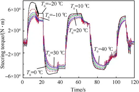
Fig.11.Influence of ambient temperature.
4.5.Influence of steering angular velocity
Based on the improved LuGre model,the influence of the angle rate on the steering torque is analyzed.The maximum turning angle of the left wheel and the right wheel is the same as the turning angle shown in Fig.8(a).The steering angular velocity varies from 2/s to 10/s,and the interval of data points is 2/s.The sum of the steering torque of the left and right rubber track assemblies is shown in Fig.12.
Due to the large steering angular velocity, the time for heat dissipation and heat transfer will be short, the local temperature rise will be serious, and even local rubber will be melted to lubricate the sliding surface and reduce friction resistance.Therefore,at the same turning angle position, as the steering angular velocity increases, the steering torque gradually decreases.Due to the dynamic performance of rubber material, when the turning angle reaches the neutral position, some of the steering torque remains and cannot reach zero.As the steering angular velocity increases,the hysteresis characteristic decreases, and the residual steering torque decrease.
4.6.Steering torque for multiple cycles
Due to the limitation of the test platform,the steering torque of the steering wheel is larger when the rubber track steering mode is adopted.Due to the limitation of the driver’s physical ability, it is difficult to maintain a stable steering speed after repeated steering,which is not convenient for the comparison of test data.Therefore,the improved LuGre model is used to simulate the changing trend of steering torque.
As shown in Fig.13(a),the steering process consists of 6 cycles.The steering angular velocity is 4/s,and the initial temperature is 10C.As shown in Fig.13(b), with the increase of cycles, the temperature of the rubber increases, which leads to the decrease of storage modulus,loss modulus,and loss tangent of rubber material,resulting in the decrease of stiffness, static friction and Coulomb friction of LuGre model.Therefore,the steering torque of the same steering angle decreases gradually.
With the increase of temperature,the storage modulus and loss modulus of rubber materials tend to decreases, while the decline rate of steering torque gradually decreases.
4.7.Influence of pavement type
Using the curve of turning angle shown in Fig.8(a) and the friction coefficient shown in Table 2,the improved LuGre model is used to simulate the changing trend of steering torque on different pavements.
As shown in Fig.14, the analysis results show that the steering torque is the largest on dry concrete or asphalt roads.The steering torque required on wet asphalt roads is second only to that on dry concrete or asphalt roads.The steering torque required on wet concrete roads is less than on wet asphalt roads.The steering torque required on dry dirt roads is less than on wet concrete roads.The steering torque required on gravel roads is minimal.The changing trend of the steering torque required for different roads is consistent, and the steering torque gradually decreases with the steering process.

Fig.12.Influence of steering angular velocity.
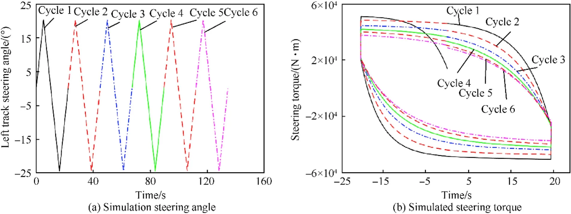
Fig.13.Influence of steering angular velocity.
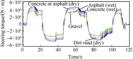
Fig.14.Steering torque of different pavements.
5.Conclusions
A modified LuGre dynamic friction is proposed for the tire and rubber track interchange chassis.Firstly, the friction temperature rise model of the rubber is established.By utilizing the influence of temperature on storage modulus,loss modulus,and loss tangent of rubber material, the relationship between the above mentioned dynamic performance parameters and the stiffness, Coulomb friction, and static friction of the LuGre model was analyzed, and an improved LuGre model was obtained.Through the above analysis,the following conclusions can be drawn:
(1) Compared with the original LuGre model, the simulation results of the improved LuGre model are more consistent with the experimental data,thus verifying the validity of the model.
(2) The modified LuGre model shows that the friction between rubber track and ground is mainly elastic friction.The steering torque caused by other factors only accounts for a small part of the total steering torque.
(3) Because the properties of rubber material are greatly affected by temperature, the maximum steering torque produced differs greatly at different initial temperatures.When the temperature is above the glass transition,the initial steering torque decreases with increasing initial temperature.
(4) With the increase in the number of steering cycles, the temperature of the rubber increases,and the steering torque decreases gradually when the steering cycles are repeated.
(5) The steering torque is affected by the type of ground.The steering torque is greatest on dry concrete or asphalt roads,followed by wet asphalt roads,then wet concrete roads,then gravel roads, and the smallest is dry dirt roads.
The authors declare that they have no known competing financial interests or personal relationships that could have appeared to influence the work reported in this paper.
This research was funded by the National Key Research and Development Program of China (Grant No.2016YFC0802900),which is gratefully acknowledged.
杂志排行
Defence Technology的其它文章
- Defence Technology
- Roll angular rate extraction based on modified spline-kernelled chirplet transform
- Buckling of composite cylindrical shells with ovality and thickness variation subjected to hydrostatic pressure
- Preparation of the core-shell HMX@CS microparticles by biological excitation:Excellent hydrophobic-oleophilic properties and decreased impact sensitivity effectively
- Quantitative prediction and ranking of the shock sensitivity of explosives via reactive molecular dynamics simulations
- An efficient light-to-heat conversion coupling photothermal effect and exothermic chemical reaction in Au NRs/V2C MXene membranes for high-performance laser ignition
