Development of a subchannel code for blockage accidents of LMFRs based on the 3D fuel rod model
2022-05-12XiaoLuoLianKaiCaoWenPeiFengHongLiChen
Xiao Luo · Lian-Kai Cao · Wen-Pei Feng · Hong-Li Chen
Abstract To predict the thermal-hydraulic (T/H) parameters of the reactor core for liquid-metal-cooled fast reactors (LMFRs), especially under flow blockage accidents, we developed a subchannel code called KMC-FB.This code uses a time-dependent, four-equation, singlephase flow model together with a 3D heat conduction model for the fuel rods, which is solved by numerical methods based on the finite difference method with a staggered mesh. Owing to the local effect of the blockage on the flow field, low axial flow, increased forced crossflow,and backflow occur.To more accurately simulate this problem, we implemented a robust and novel solution method. We verified the code with a low-flow (~0.01 m/s) and large-scale blockage case. For the preliminary validation, we compared our results with the experimental data of the NACIE-UP BFPS blockage test and the KIT 19ROD blockage test. The results revealed that KMC-FB has sufficient solution accuracy and can be used in future flow blockage analyses for LMFRs.
Keywords Subchannel method · Code development ·Blockage accident · Liquid-metal-cooled fast reactor
1 Introduction
Fourth-generation liquid-metal-cooled fast reactors(LMFRs),including the lead-cooled fast reactor(LFR)and sodium-cooled fast reactor (SFR), have application prospects in the future nuclear power sector because of their high level of inherent safety,advantages in new fissile fuel breeding,and minimization of nuclear waste.In particular,LMFRs are expected to provide a safe and self-protected response to the Fukushima scenario because of the abovementioned features providing high thermal inertia.
Although LMFRs have the above advantages, some safety issues have been noted by researchers during the design and operation of the above-mentioned prototypes or experimental reactors, such as the sodium boiling problem[1], flow blockage accidents [2], erosion problems [3], the production of polonium-210 under neutron irradiation of Bi[4], the temperature control problem, and the in-reactor detection of opaque liquid metal [5]. Therefore, in recent years, efforts have been directed toward improving the safety of LMFRs.One method that can avoid the high cost of experiments and quickly predict the operating parameters under the design parameters of the reactor is the development and application of various numerical simulation programs.
Flow blockage is one of these postulated accidents and events affecting LMFRs; these blockages can form for the following reasons [6]: (1) accumulation of corrosion products, (2) swelling and curving of the cladding, (3)shedding of the wire-wrap spacer,and(4) accumulation of other impurities. The detailed accident process diagram is shown in Fig. 1 which we divided into three parts: (1) the formation of the blockage accident, (2) the dynamic development of the core parameters after the blockage,and(3)the accident process after the pellets melted.At present,research on reactor blockage accidents can be roughly categorized into two aspects: experimental research and numerical simulation. In terms of experimental research,the USA, Germany, Japan, Italy, and other countries have successively conducted a series of experimental studies on the blockage accidents of single-fuel assemblies since the 1970s, considering liquid sodium, air, water, and leadbismuth alloys(LBE)as coolants[6-11].For example,KIT conducted a heat transfer experiment with LBE flowing through a partially blocked 19-rod bundle fixed by a wire spacer [10]. ENEA constructed an experimental platform called a blocked fuel pin bundle simulator(BFPS)installed in the NACIE-UP facility to study the thermal-hydraulic features under different blockage situations [11].
However, owing to factors such as the high cost and requirements of the experimental facility, conducting such blockage experiments is difficult. Most of the research has focused on numerical simulations and the study of related theoretical models for blockage accidents, which can be divided into five main categories:
· Computational fluid dynamics (CFD) can be used to carry out three-dimensional (3D) thermal-hydraulic analysis of blockage accidents [12, 13]. With a refined model and an appropriate turbulence model, the local flow field can be accurately obtained,but the simulation cost is much higher than that of the following tools.
· One-dimensional system analysis codes can be used to obtain the thermal hydraulic parameters under flow blockage conditions. Examples of these methods include RELAP and ATHLET [14-16]. These codes can quickly calculate the core outlet temperature in the case of a flow blockage,but the local parameters inside the fuel assembly cannot be accurately obtained owing to the application of the lumped parameter method.
· A 1.5-dimensional subchannel code can be used to predict the maximum coolant temperature, maximum cladding temperature,and pellet temperature in the fuel assembly under steady state or transient flow blockage accidents. Examples include COBRA-IV, SABRE4,and MATRA-LMR [17-19]. However, most of the existing subchannel codes for LMFRs adopt a relatively simple blockage model, and the details still remain to be resolved.
· Serious accident analysis codes can be used for accidents that occur after a large-scale blockage and may result in core melting, such as SIMMER,ATHLET-CD, and RELAP5/SCDAP [20-22]. These codes have the advantages of performing dynamic system analysis under severe accidents of the reactor core but perform poorly for fine local analysis.
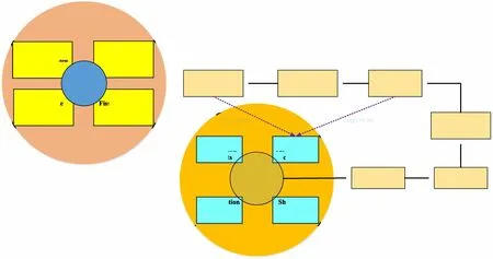
Fig. 1 (Color online) Incident progression of reactor core flow blockage accidents
· Multi-physics coupling programs can be used to analyze the comprehensive impact on the neutron physics, T/H, and structural safety [23-25]. However,the basis of coupling is the mature development of each subtool.
The subchannel thermal hydraulic analysis method has been used in nuclear engineering for many years. In this method, the fuel assembly is artificially divided into several subchannels,and the conservation equation of the flow field and the heat conduction equation of the fuel rod are solved simultaneously to obtain the distribution of temperature, flow rate, and pressure in the assembly. As such,in this study, we applied the subchannel method to the reactor core flow blockage accident.We mainly focused on the second part of Fig. 1: calculating the consequences of the accident without considering the fictitious accident caused by the blockage and melting.
In our previous work, we developed a subchannel code KMC-SUBtra for transient thermal hydraulic analysis of LMFRs[26].In this study,our objective was to expand the capability of KMC-SUBtra in dealing with this type of accident. Based on this goal, we constructed a new numerical solution method, adopted a more refined threedimensional heat conduction model, and performed an indepth study of blockage-related models (i.e., axial resistance model, heat transfer model, etc.), which laid the foundation for our upgraded code (referred to as KMCFB). In addition,to ensure the correctness and accuracy of KMF-FB, a low-flow (~0.01 m/s) and large-scale blockage case was used to test the code, and we preliminary validated the code by comparing its results with the experimental data of the NACIE-UP BFPS blockage test and the KIT 19ROD blockage test.
2 Basic conservation equations and physical models
2.1 Basic conservation equations
The subchannel code KMC-FB adopts the finite difference method(FDM)with a staggered mesh,which adopts a scalar field grid for the conservation continuity equation and energy equation, and uses a vector grid for the momentum equation (axial and lateral). The height of the control cell is half-staggered between the two grids, as shown in Fig. 2. Owing to the assumption that the liquid metal does not boil, a four-equation, single-phase flow model including the continuity equation, axial and lateral momentum equation, and energy conservation equation is used, which is expressed in the form of differential equations, as shown in Eqs. (1)-(4). The meanings of the variables used in the following equations are provided in the nomenclature.

Fig. 2 (Color online) Staggered mesh of KMC-FB


2.2 Heat conduction equation
Currently,most subchannel codes,such as COBRA and MATRA, adopt a one-dimensional model to simulate the heat conduction of fuel rods. Under normal conditions, the temperature difference between each subchannel and the circumferential unevenness of the fuel rod are small,which indicates that this method is acceptable.However,for some reactor types whose coolant physical properties vary widely with temperature (i.e., supercritical water-cooled reactors[SCWRs])or where serious asymmetry of the fuel rod circumference is caused by an accident (i.e., flow blockage accident), the limitations of this method are obvious.
In this study, we used a three-dimensional heat conduction model tightly coupled with fluid conservation equations. For comparison, we also implanted a one-dimensional heat conduction equation and a circumferential subnode model in KMC-FB. The one-dimensional heat conduction equation usually does not consider the heat conduction of the circumferential nodes, and the axial temperature depends on the boundary conditions of the convective fluid, as shown in Fig. 3a. The circumferential subnode model simply considers that the fuel rods are split according to the surrounding subchannels, as shown in Fig. 3b. The three-dimensional heat conduction model considers the heat conduction of the fuel rod in the axial,radial, and circumferential directions, as shown in Eq. (5)and Fig. 3c:

Fig. 3 (Color online)Schematic diagram of the three heat conduction models of fuel rods

2.3 Hybrid difference scheme
Blockage accidents can lead to local low flow rates and backflow phenomena,which are similar to the flow around a cylinder and change the flow from Stokes flow to turbulent flow through a laminar region [27]. If the upwind scheme is used in all flow regions, a larger numerical diffusion will occur in the local low-velocity flow and the circulating flow region after the blockage. To avoid this numerical dissipation,the hybrid difference method[28]is adopted, which combines the advantages of the central difference scheme and the upwind difference scheme. The central difference scheme is used when Re is smaller than 2 or Pe is smaller than 2, and the upwind difference scheme is used in other cases. Specifically used in the subchannel conservation equation, the convection term of the momentum and energy equations can be expressed as Eqs. (6)-(8):

2.4 Flow and heat transfer model
Similar to the previous subchannel code KMC-SUBtra,various heat transfer and friction factor correlations are used in the updated code (KMC-FB), and a detailed presentation was provided by Cao et al. [26].
In addition, the heat conduction in the blockage is important for the prediction of the maximum temperature of the cladding and the temperature of the coolant in the case of a blockage. The total heat transfer coefficient (k)between the subchannel and the cladding in the blockage flow area can be expressed as the Karlsruhe blockage equation (KBE) [10] in Eq. (9), where Rblis the blockage thermal conductivity and Rfis the convection in the fluid.An empirical coefficient r1>0 indicates that thermal conduction dominates in the solid blockage.

2.5 Flow resistance model

2.6 Property models
We obtained the property correlations of sodium [30]and integrated them into KMC-FB. We also obtained the property correlations of Pb and LBE [31].Both are widely used in the thermal hydraulic analysis of LMFRs.
3 Numerical solution method
3.1 Solution method for flow field

Fig.4 Flow through a thick-edged blockage in a straight tube(channel) [29]
KMC-FB used an implicit iterative method as the numerical solution method,which refers to the ideas of the SIMPLE and Newton-Raphson iterative methods but is different enough that its process needs to be described:
1. Initialize a reasonable pressure field, flow velocity field,and temperature field according to the user-input parameters, which favors the convergence speed.
2. Solve the axial and lateral momentum equations and obtain the tentative flow field that satisfies the momentum equation.
3. Calculate the residual error of the continuity equation considering the influence of the upper, lower, and laterally adjacent nodes for a given node;construct the pressure Poisson equation; and obtain the pressure correction in the specified fuel assembly at one time.
4. Update the pressure and flow rate based on the momentum equations.
5. Solve the flow field energy equation and the fuel rod heat conduction equation and update the thermophysical properties.
6. Verify whether the thermal hydraulic parameters converge or exceed the specified number of iteration steps. If yes, exist the iteration process and output the result;if not,return to step(1)to continue the iterative calculation.
3.2 Solution method for solid
To solve the three-dimensional heat conduction equation of a solid,the numerical solution method used in KMC-FB is Brain-alternating direction implicit (ADI), which is unconditionally stable when solving three-dimensional problems [32].


4 Code verification and validation
To ensure the correctness and applicability of the above theoretical model and to test the robustness of KMC-FB,we performed preliminary validation and verification(V&V). The verification process was used to ensure that the program functions are consistent with the expectations.Hence, we chose two cases to test the code’s ability to handle low flow rates and circulating flows.In addition,we constructed a validation matrix based on existing liquid metal bundle blockage experiments, the NACIE-UP and KIT THEADS blockage experiments,as shown in Table 1.
4.1 Code verification
4.1.1 Very low flow (~0.01 m/s)
In an unprotected loss of flow accident (ULOF), the liquid metal in the reactor is driven only by natural circulation, which is always followed by a low flow phenomenon. Owing to the low flow rate, the numerical solution method must be sufficiently stable. To test the ability of KMC-FB to handle this situation, we artificially constructed a very-low-flow case: a 61-pin test with wirewrapper spacers cooled by an LBE. All fuel rods were 13.1 mm in diameter and arranged in a triangular pitch within a hexagonal duct. The wire spacers had a diameter of 1.4 mm and a pitch of 210 mm. All the liquid LBE flowed from the bottom to the top and passed through a 350-mm inlet zone and a 1000-mm heating zone.The inlet flow was 0.5797 kg/s at the mass flow rate and 283.5 °C.All fuel rods were heated uniformly with a total thermal power of 11.39 kW.
The test section was modeled with 100 axial nodes in the heated zone and 30 axial nodes in the inlet zone (total axial nodes = 130, each axial level = 10 mm). Figure 5a shows the convergence residuals in the calculation process,in which the red dotted line is the convergence residual limit set by the user.As shown in Fig 5a,with the improved novel solution method, the residual error of each physical quantity decreased steadily as the iteration progressed and finally reached the limit set by the user. The subchannel number and simulation results by KMC-FB for the 61-pin low-flow test are depicted in Fig. 5b,c. The inlet flow rate was approximately 0.01 m/s, and the minimum flow rate was approximately 0.008 m/s located at the edge channels(#1 and #18) owing to their smaller volume power density and higher frictional resistance.
4.1.2 Multiple blockages
Based on the worst-case hypothesis, we constructed multi-axial level and multi-subchannel flow blockage accident with a 19-pin assembly, and performed a simulation. Figure 6a shows a schematic diagram of the blockage position, which had four axial planar blockages and six central subchannel blockages. The six blockage subchannels were distributed in four axial positions with an axial interval of 5 cm.The rod bundle was cooled by LBE,which flowed from the bottom to the top and passed through a 100-mm inlet zone and a 600-mm heating zone.All fuel rods were 10 mm in diameter and arranged in a triangular pitch within a hexagonal duct. The simulation results obtained using KMC-FB for the 19-pin multiblockage test are shown in Fig. 6b, c. The obvious backflow phenomenon was captured by KMC-FB, and the maximum downward flow rate was approximately 0.1 m/s.A temperature peak occurred near each blockage, and the temperature gradually increased axially with the increase in the blockage numbers, which caused the overall temperature profile to present a trapezoid in the flow direction,resulting in the outlet temperature being noticeably uneven.
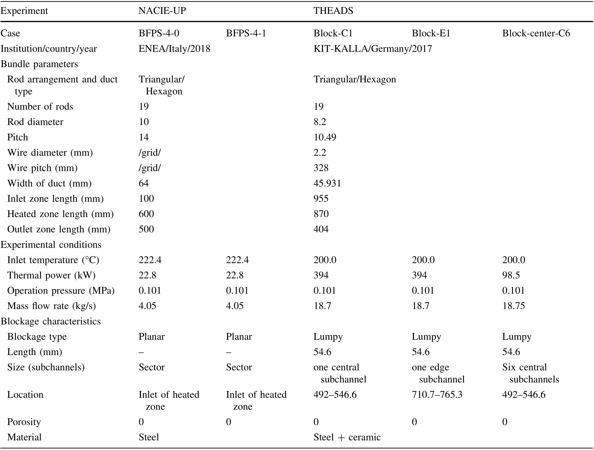
Table 1 Experimental parameters of the verification matrices

Fig. 5 (Color online) Results of the 61-pin test bundle: a residual monitoring window of KMC-FB; b schematic diagram; and c axial velocity contour
4.2 Preliminary validation
4.2.1 NACIE-UP blockage experiment
In the framework of the research activities planned to support the development of the ALFRED reactor, ENEA performed experimental tests to simulate the thermal-hydraulic behavior of a pin fuel bundle that is LBE-cooled in a flow blockage accident scenario,which was performed at the Natural Circulation Experiment-Upgraded) (NACIEUP)facility loop with a heat source(a BFPS)consisting of 19 electrical pins. The experimental campaign focused on different stationary tests characterized by three different mass flow rates (4, 8, and 12 kg/s) and five fundamental degrees of blockage. In this study, as validation cases, we chose a normal condition (without blockage, referred to as BFPS-4-0) and a sector blockage case (BFPS-4-1). The instrumentation in the NACIE-UP facility allowed us to directly measure the nominal power of the LBE mass flow rate of the LBE temperatures in the loop, localized wall,and subchannel temperatures in the bundle. In this study,we mainly compared the differences in the values of temperatures of the subchannel and the wall surface of the electric heating rod produced by the code and the experiment.
Figure 7 represents a top-view section of the BFPS in the case of sector blockage, and the position of the thermocouples. The key geometric parameters and boundary conditions of the experiments are listed in Table 1. The simulation results produced by KMC-FB for the BFPS tests are depicted in Fig.8a-e,where the x-coordinate represents the axial height from the entrance of the heated zone(mm),the y-coordinate represents the temperature, and 1.5D,2.5D, and 3D in the legend represent the one-dimensional heat conduction model, circumferential subnode model,and three-dimensional heat conduction model used in KMC-FB, respectively, which were previously mentioned in Sect. 2.2. The experimental data are shown in Fig. 4,where SB2 represents the center of subchannel B2.

Fig.6 (Color online)Results of the 19-pin multi-blockage test:a schematic diagram; b axial velocity contour; and c coolant temperature contour
Figure 8a-d, which represents the experiment without a blockage, shows that the calculation results of the code closely followed the experimental data, and the maximum relative error did not exceed 1%. Owing to the uniform heating power, the wall temperature of the rod bundle increased linearly with height. The results in Fig. 8a-d show that the calculation results of the 1.5D,2.5D,and 3D models were basically the same;because the nonuniformity of the fluid temperature around these rods was small, the circumferential subnode model and the three-dimensional heat conduction model showed no obvious effect.
Figure 8e shows the distribution of the temperature of subchannel SB2 along the height of the flow path. The figure shows that the profile shape and the magnitude of temperature described by KMC-FB are in good agreement with the experimental results, and the maximum relative errors of all three models do not exceed 1.1%;their results are basically the same.

Fig.7 (Color online) Schematic diagram of the blockage subchannels: a location of the thermocouples used in BFPS (b) [10]
The BFPS-4-1 case corresponds to approximately 1/6 of the flow area being fully blocked, and the blockage solid being a thin plate located at the beginning of the heated zone. Figure 9a-d shows the temperature distributions of the #1, #2, #5, and #15 pins along the axial direction.Because pins #1, #5, and #15 were all located in the blocked flow area, the axial temperature distribution showed a similar trend, but the specific value and change range were different, which was closely related to the pin position and the degree of blockage of the circumferential subchannels.
Generally, the linear profile was maintained for pin 2,which faced an unblocked sector E,while all the other pins exhibited the behavior of a maximum, a local minimum,followed by a linear trend.From the perspective of the fuel rod models in the blockage area, the average effect of the one-dimensional fuel rod model severely underestimated the temperature peak of the pins behind the blockage. The three-dimensional fuel rod model was more accurate for predicting the local peak temperature under severe asymmetric conditions. However, at 30-100 mm, as shown in Fig. 9a, the temperature predicted by KMC-FB showed a certain deviation from the experimental value, which may be due to the weak prediction effect of the corner channel.

Fig.8 (Color online) Comparison of simulation results between the values predicated by KMC-FB and the NFPS-4-0 experimental values: ad pin temperature and (e) coolant temperature
For the coolant temperature (Fig. 9e), the calculation results produced by KMC-FB were generally in good agreement with the experimental results,and the maximum deviation did not exceed 3.1%. For the three different fuel rods, the three-dimensional fuel rod model was the closest to the experimental results, which proved that the circumferential heat flux density of the fuel rod was no longer uniformly distributed in this case,and was closer to the real experimental environment.
4.2.2 KIT-THEADES blockage experiment
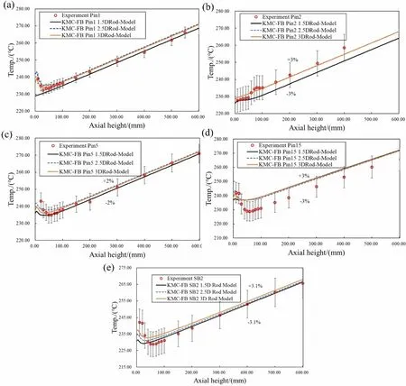
Fig. 9 (Color online) Comparison of simulation results between KMC-FB and NFPS-4-1 for a-d pin temperature and e coolant temperature
Within the European project MAXSIMA, the thermalhydraulic effects of internal flow blockages in a heated rod bundle cooled by lead-bismuth eutectic (LBE) were investigated using a test section installed in a vertical test port of the existing THEADES loop facility at KITKALLA. In this study, we considered two blockage scenarios: a small blockage covering one subchannel, and a large blockage covering the six central subchannels, as shown in Fig. 10a, in which the six gray subchannels represent the Block-center-C6 case, the black central subchannel represents the Block-C1 case, and the black edge subchannel represents the Block-E1 case.In this part of the study, we used KMC-FB to simulate these two blockage scenarios.Because there were too few thermocouples in the coolant subchannel (only three),we mainly focused on the influence of different heat conduction models on the wall temperature of the rod bundles;the simulation results of the coolant temperature were produced by KMC-FB using the three-dimensional heat conduction model. The key geometric parameters and boundary conditions of these cases are listed in Table 1.
Figure 10b compares the temperature of the five thermocouples at the axial center in the blockage zone and the values predicted by the code under the first blockage scenario. We found that the temperature of points A-E calculated by the one-dimensional fuel rod model was basically the same, indicating the model could not reflect the circumferential unevenness caused by the blockage around the fuel rod. In addition, the circumferential subnode model adopts the subnode assumption and does not consider the circular conduction heat; therefore, the circumferential nonuniformity was too large, and the prediction of node B was obviously higher. Generally, the 3D fuel rod model more closely followed the experimental data, and the maximum deviation did not exceed 9%.However, the code did not accurately predict the temperature at points A and C, which may have been due to the local effect of the wire spacer, but the code adopts a simplified C-T correlation and can only consider the average effect of a wire spacer.

Fig. 10 (Color online) Comparison of the simulation results produced by KMC-FB and the THEADS blockage experiment: a view of the test section, b, d, f pin temperature, and c, e, g coolant temperature
Figure 10c compares the temperature in the blocked subchannel,where the distance is expressed as a fraction of the wire pitch (H = 328 mm). The predicted value of the code was accurate, with a maximum deviation of 2%.Fig.10d,e shows the simulation results of the second small blockage. Similar to the first case, the code predicted an accurate value with a maximum deviation of 4% at points C and F, with a maximum deviation of 6% in the subchannel temperature.
The simulation results produced by KMC-FB for the second scenario (large blockage) are depicted in Fig. 10f,g. Because the subchannels around fuel rod #1 were completely blocked, their circumferential temperature was basically the same. Therefore, the values predicted by the three-dimensional fuel rod heat conduction model and the one-dimensional heat conduction model were similar.However, the temperature of the circumferential subnode model at points B and C was obviously higher,mainly due to ignoring the circumferential heat conduction. As for the coolant temperature, the calculation results of the code were in good agreement with the experiment, and the deviation did not exceed 5%.
5 Conclusion
The analysis of reactor blockage accidents is an indispensable part of research on reactor safety analysis, especially for liquid metal fast reactors that are featured by a compact reactor core layout and high power density.In this study,we developed a subchannel code called KMC-FB to analyze blockage accidents in a reactor core.The code uses a time-dependent, four-equation, single-phase flow model together with a 3D heat conduction model for the fuel rod,which is solved by numerical methods based on the FDM with a staggered mesh. In addition, we proposed and implemented a novel and robust numerical solution method for the flow field solution in KMC-FB.
We verified the code to demonstrate its strong ability to handle low flow rates and circulating flow cases. The first case considered was a very-low-flow case (~0.01 m/s)with a 61-pin bundle,and KMC-FB successfully calculated its flow velocity distribution.The second case was a multilevel and subchannel flow blockage accident with a 19-pin assembly, and KMC-FB successfully simulated the locally low flow rate and reverse-flow phenomenon. We performed a preliminary validation by comparing the results produced by KMC-FB with the experimental data of the NACIE-UP BFPS blockage test and the KIT 19ROD blockage test, which included normal working conditions(no blockage), planar blockage, small solid blockage, and large solid blockage. We obtained agreement with the experimental data,with a relative deviation interval of[1%,9%], which indicated that the code is capable of performing flow blockage analysis for LMFRs.
In addition, we used a three-dimensional heat conduction model together with the one-dimensional heat conduction model and the circumferential subnode model for comparison. The verification results showed that (1) under normal operating conditions, the accuracy of the one-dimensional heat conduction model is sufficient for subchannel thermal-hydraulic analysis. (2) In flow blockage accidents or similar conditions that can cause large circumferential and axial temperature gradients of the fuel rods,the three-dimensional heat conduction model is more accurate. (3) The fuel rod circumferential subnode model can sometimes predict accurately, but at other times, it overestimates the fuel rod temperature, which depends on how much it is blocked in the surrounding subchannels.
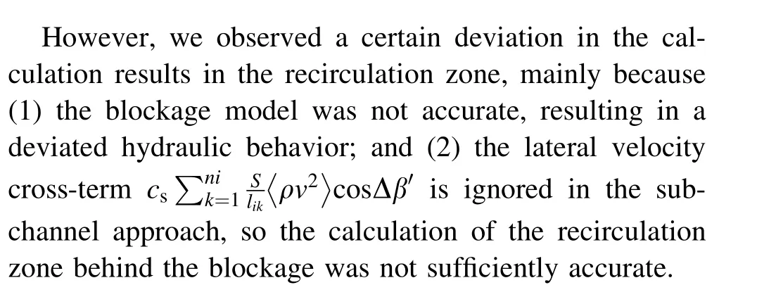
Future work will focus on several aspects to improve simulation accuracy, which will involve (1) searching for more accurate hydraulic and heat transfer correlations when the flow is blocked or the crossflow is dominant to improve the calculation accuracy of the subchannel code in the recirculation zone;and(2)constructing a more accurate wire-wrapper spacer model.
Author contributionsAll authors contributed to the study conception and design. Material preparation, data collection, and analysis were performed by Xiao Luo, Lian-Kai Cao, Wen-Pei Feng, and Hong-Li Chen. The first draft of the manuscript was written by Xiao Luo, and all authors commented on previous versions of the manuscript. All authors read and approved the final manuscript.
杂志排行

Nuclear Science and Techniques的其它文章
- Design and tests of the prototype a beam monitor of the CSR external target experiment
- Development of a wide-range and fast-response digitizing pulse signal acquisition and processing system for neutron flux monitoring on EAST
- On the viability of wearing evaluation by Thin Layer Activation in the presence of non-occupationally exposed individuals
- Enhancement in optical absorption of CsI(Na)
- Research on tune feedback of the Hefei Light Source II based on machine learning
- Robust restoration of low-dose cerebral perfusion CT images using NCS-Unet