Research on tune feedback of the Hefei Light Source II based on machine learning
2022-05-12YongBoYuGongFaLiuWeiXuChuanLiWeiMinLiKeXuan
Yong-Bo Yu· Gong-Fa Liu· Wei Xu· Chuan Li · Wei-Min Li ·Ke Xuan
Abstract The theory of tune feedback correction and the principle of a feedback algorithm based on machine learning are introduced, with a focus on the application of lasso regression for tune feedback correction. Simulation verification and online feedback correction results are presented. The results show that, after applying machine learning, the feedback accuracy of the tune feedback system was higher, and the betatron tune stability was further improved.
Keywords Storage ring · Tune feedback · Machine learning · Lasso regression
1 Introduction
For synchrotron light sources,high stability of the beam is a tremendous advantage. Synchrotron light sources with electron storage rings can continuously supply light for several hours without interruption. Moreover, synchrotron light sources with a top-off operation offer a longer continuous light supply time, facilitating highly stable optical properties and various spatial geometrical properties of the generated synchrotron light. This means that the synchrotron light on the sample is more stable in synchrotron radiation experimental research and is more conducive to improving the resolution of experimental data.
At present, beam stability is an important long-term concern for foreign and domestic laboratories,regardless of whether the synchrotron light source is under design or operation. To meet the design specifications or further improve beam stability, appropriate measures must be proposed for the machine. Although existing technologies are being used to improve beam stability,new technologies are being sought to improve beam stability [1-4].
Recently, in the field of accelerators, operators of the Large Hadron Collider in Europe have developed a machine-learning method for optical correction.According to the relationship between the Beam Position Monitor position and the quadrupole,the effect of optical correction is better than that of the traditional response matrix approach, and the application of local and global corrections was completed in a later study. In addition, self-encoder neural networks and linear regression measurement data denoising and reconstruction techniques have been proposed [5, 6]. At the Stanford Positron Electron Asymmetric Ring, an adaptive feedback method to rapidly optimize and continuously optimize the magnet, even for an unknown magnet that changes rapidly,can continuously adjust all other magnets to minimize mismatches and the resulting betatron oscillations [7]. In this work, for the Hefei Light Source II (HLS-II) storage ring, we focus on tune correction using machine learning and a feedback method for correction.
In the storage rings, the betatron tune is the number of transverse oscillation periods in one turn. Betatron tune should avoid critical resonance lines and remain stable for user operation [8]. In the synchrotron light source storage ring, the tune reflects the number of transverse oscillations of the beam in each gyration cycle, and the stability of the tune directly affects beam stability.The tune is affected by various factors that may be static or dynamic [9]. Static factors, such as manufacturing errors in the magnet and installation errors,can be compensated for during machine commissioning.However,dynamic factors can lead to tune shifts. They are usually caused by changes in insertion devices (IDs).
The Hefei Light Source (HLS) is a second-generation dedicated synchrotron light source built in 1989. The HLS underwent a significant upgrade beginning in 2010 and completed by the end of 2014. This new light source was renamed as HLS-II. The HLS-II storage ring operated at 800 MeV with a tune (4.4448, 2.3598) [10], and five IDs were installed on the storage ring to produce high-quality synchrotron light with different characteristics. The ID variation causes the tune to shift and changes the beam quality,affecting the user experiment.Although the HLS-II employs lattice compensation for the IDs, owing to the small size of the HLS-II storage ring, the tune of the storage ring will still fluctuate when multiple IDs change simultaneously; therefore, a tune feedback correction system is needed to stabilize the tune.
Tune stability is important for the performance of transverse bunch-by-bunch feedback systems, which plays an important role in suppressing collective beam instabilities for modern and next-generation synchrotron light sources [11].
The remainder of this paper is organized as follows:Sect. 2 presents the beam tune correction theory.Section 3 describes tune correction of the storage ring based on machine learning. Section 4 discusses model training.Section 5 presents the experiments and results. Finally,conclusions are summarized in Sect. 6.
2 Beam tune correction theory
A variety of approaches may be used to rectify the storage-ring tune distortion,but the main idea is to change the quadrupole strength to achieve the desired result.
When no quadrupole error exists, the one-turn transfer matrix at siis given by
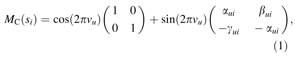
where αui, βui, and γuiare betatron amplitude functions of the unperturbed machine.
Next, we consider a gradient perturbation ΔK /=0 at si.Except for si, the quadrupole of the entire ring is perfect,and the transfer matrix of this infinitesimal localized perturbing quadrupole error MAis as follows:
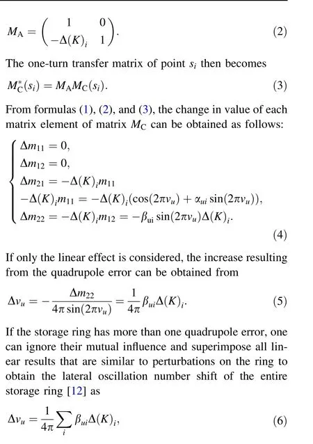
where ΔK is the quadrupole strength, βuirefers to the beta function at location s, and Δvudenotes the tune change.From Eq. (6),it can be seen that,as long as the quadrupole strength is changed, the tune can be corrected.
3 Tune correction of the storage ring based on machine learning
Although the relationship between the tune and the quadrupole can be obtained by using formula (6), beta is not easy to obtain online; therefore, we want to directly obtain the relationship between the tune and the quadrupole through machine learning.
To establish a machine-learning-based feedback correction for the tune, we need a storage ring beam tune model and a tune correction study based on this model.
3.1 Establishing the storage ring beam tune model
A substantial amount of training data is required for machine learning, and the quality of the data is critical to the effectiveness of the storage ring beam tune model(STM). To develop an accurate STM, accurate training data that accurately represent real beam dynamics must be collected.
To create a virtual storage ring with the HLS-II lattice as the object with MATLAB toolbox AT [13], we used a virtual storage ring to add a random set of errors to the quadrupole to calculate the storage ring tune, thereby generating numerous data pairs corresponding to the tune and quadrupole value to form a simulated training dataset(simulated data). Simultaneously, the strength of the quadrupole was randomly changed on the HLS-II at tuning and machine study time, and the storage ring tune was measured to obtain the online training dataset composed of the tune and the value of the quadrupole (real machine data). Together, these two parts served as the model training data.
After obtaining the training dataset, including simulation and real data, machine-learning methods were used to analyze the data pair to create an STM.
Presently, there are many accessible machine-learning algorithms, each with advantages and disadvantages. The lasso regression technique is a highly effective tool for predictive modeling.This machine-learning method can fit our tune correction problem well. The basic lasso regression is used to build the STM,which starts with the reality of beam tune feedback correction and works its way up.
It is necessary to enter the training data into the model after it has been constructed, and the STM should be trained according to the loss function of the lasso regression, as previously described. It is feasible to develop an STM that accurately represents the relationship between the tune error and quadrupole value error after training and testing to accumulate a large amount of data.
3.2 Tune feedback based on the model
The feedback correction of the tune was performed based on the generated STM.Figure 1 shows a diagram of HLS-II tune feedback correction.
The following are the exact steps involved in tune feedback correction:
· The tune of the storage ring was measured.
· The tune error was calculated.
· The tune error was input into the STM to predict the quadrupole error (output).
· A modification was made to the storage ring quadrupole strength in response to the predicted value of the change in the quadrupole strength.
The above procedure was repeated until the tune of the storage ring was adjusted, and, after several iterations, the tune of the storage ring beam was rectified.

Fig. 1 Schematic of the tune feedback system using a machinelearning method. SR is the storage ring, and STM is the storage ring beam tune model. The input is the tune error, and the output is the quadrupole value error
4 Storage ring beam tune model training
The regression problem is a function-fitting process.Regularization was added to avoid overfitting during the fitting process.The ℓ1-norm was added to the regression in lasso, and the loss function expression for the lasso regression is

where Xw-y is the predicted value minus the true value,nsamplesis the number of samples, α is a constant that must be tuned, and ||w||1is the L1 regularization term [14].Lasso regression was solved using the coordinate descent method [15, 16], and it performs constant iterations to solve the parameters.
Lasso regression can make the coefficients of some features smaller, and even coefficients with smaller absolute values directly become zero, which enhances the generalization ability of the model.
Because we built an STM using the lasso regression model, the training optimization algorithm of the tune learning model has two parts: the loss term, which is used to measure the model’s fit to the data, and the regularization,which is used to describe the complexity of the model.
The convergence properties of the lasso method are highly sensitive to the regularization coefficient α, which must be carefully chosen when training the STM. We find our α parameter by following a procedure that we refer to as a ‘‘regularization path,’’ which is described in more detail below.
It follows that, if the tune matrix has only two features,there will be two feature vectors, vxand vy. For each α value taken, we can derive a set of parameter vectors corresponding to this feature vector w, including three parameters denoted by w0, w1, and w2, with w0as a separate intercept.These parameters can be considered a point in three-dimensional space, and, for different α values, we obtain many points in the three-dimensional space,and the sequence formed by all these points is called a regularized path. Simply put, a regularization path is a plot of all coefficient values against the α values.
The path length is calculated by dividing the minimum value of α by the maximum value of α. We call this the amount αmin/αmax(path length).We can calculate the value of α by specifying the length of the regularized path and the number of α values in the path, using the coordinate descent method to optimize the loss function, using crossvalidation to determine the best value of α, and finally evaluating according to the model under this regularization coefficient indicators are modeled.
A dataset of 60,000 samples(50,000 simulated data and 10,000 real machine data) was divided into training and testing datasets. (70% and 30% respectively), with each sample pair consisting of 2 inputs (tune errors) and 32 outputs (quadrupole errors). We chose the length of the regularization path to be 0.0000001,the number of α values in the regularization path to be 600, and the number of cross-validations to be five each time when training the STM. The dataset was randomly partitioned into k-1 subsamples of equal size for this approach. While k-1 subsamples were used to develop a prediction, the remaining subsample was used to validate this model[17].We obtained the best STM through model training and evaluation, with a regularization parameter of 1.458×10⁻⁷(see Fig. 2)and a loss item mean squared error value of 7.419×10⁻⁵(see Fig. 3).
5 Storage ring tune feedback calibration verification
Python was used to develop a simulation application of the tune feedback correction to verify the feasibility of this storage-ring feedback correction method based on machine learning.

Fig. 2 Selecting the best value for the regularization parameter after 600 iterations
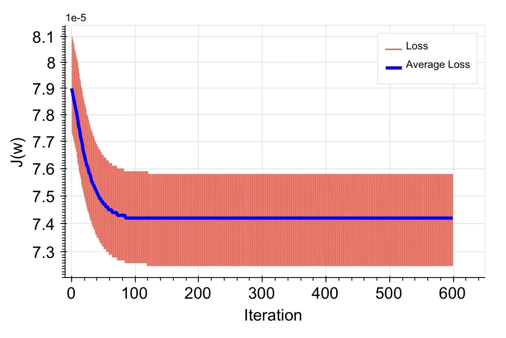
Fig. 3 (Color online) Mean squared error values for 600 iterations,each of which has been cross-validated five times, giving a range as shown in the figure.The blue line represents the average of five crossvalidations for each iteration
5.1 Simulation verification of tune feedback correction
The HLS-II physical model was built using PyAT [18]and the accelerator toolbox (AT), and a random error was added to the HLS-II physical model to simulate the storage ring tune shift and obtain the tune error.
The tune error value must be entered into the STM to obtain the change in the storage ring quadrupole strength that removes the tune error and then enters the virtual storage ring to obtain the tune. In addition, the tune correction simulation program employs a step-by-step correction to realistically model the operation of the light source and minimize severe changes in the setting of the quadrupole power supply that could compromise beam stability,as described previously.After numerous iterations of simulation correction, the resultant tune simulation value was compared with the theoretical value, and the machine-learning-based storage ring tune feedback correction method was evaluated based on the comparison result.
Four representative datasets were extracted from this larger dataset. We chose to have as large an error as possible for each direction. They cover all possible situations in actual operation.
(A) The horizontal tune is greater than the theoretical value, and the vertical tune is less than the theoretical value. Before feedback correction, the tune was(0.4675, 0.3267), and, after turning on the feedback and after several iterations, the tune was stable at(0.4448±0.0006, 0.3598±0.00008) (see Fig. 4).
(B) The horizontal tune is less than the theoretical value,the vertical one is greater than the theoretical value.The tune before the iteration was (0.4202, 0.3926);that after correction was (0.4448±0.0005,0.3598±0.00008) (see Fig. 5).
(C) The horizontal tune is less than the theoretical value,and the vertical one is less than the theoretical value.The tune before iteration was (0.4310, 0.3475); that after correction was (0.4448±0.0005,0.3598±0.00009) (see Fig. 6).
(D) The horizontal tune is greater than the theoretical value and the vertical one is greater than the theoretical value. The tune before the iteration was(0.4643, 0.3639); that after correction was(0.4448±0.0005, 0.359±0.00009) (see Fig. 7).
The above simulation measurement results show that the tune feedback correction realizes the correction of the storage ring tune and that the test range is systematic and comprehensive.The feedback accuracy satisfied the design requirements, confirming the feasibility of tune the feedback correction based on machine learning (see Table 1).
5.2 Online verification of tune feedback correction
The feasibility of the tune feedback correction technique based on machine learning has been demonstrated through simulation testing, and the effect of the tune feedback correction method based on machine learning must be validated and evaluated in real-world conditions.The steps to follow precisely are as follows:
· Perform online feedback correction of the tune code program.
· Periodically read the tune of the HLS-II through PyEpics to calculate the tune error.
· Input the tune error value into the STM to obtain the HLS-II quadrupole strength change.
· Set the change in the HLS-II quadrupole strength.
· Set the program operation interval to 2 s.
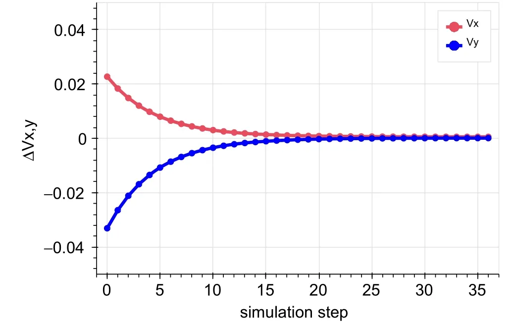
Fig. 4 Extracted dataset showing the horizontal tune being greater than that of theory and the vertical tune being smaller than that of theory

Fig. 5 Extracted dataset showing the horizontal tune being smaller than that of theory and the vertical tune being greater than that of theory
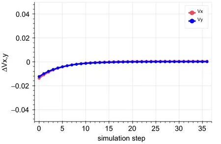
Fig. 6 Extracted dataset showing the horizontal tune being smaller than that of theory and the vertical tune being smaller than that of theory

Fig. 7 Extracted dataset showing the horizontal tune being greater than that of theory and the vertical tune being greater than that of theory
Because the HLS-II employs a physical-quantity-based control mechanism, it can directly influence the physicalquantity being measured or controlled [19]. The physicalquantity-based control system provides an effective mechanism for sharing the same hardware with different physical functions. For example, a quadrupole must be used in addition to the basic operating parameters of the accelerator to adjust the operating parameters of the machine and compensate for the additional focusing force generated by other components in the system(such as IDs).As a result, we divided the function of the quadrupole strength into several corresponding functional blocks to realize that different physical functions share the same quadrupole.
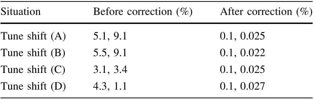
Table 1 Tune before and after STM correction
In developing the HLS-II physical-quantity-based control system,we designed the corresponding EPICS[20-22]records for the quadrupole for the physical functions to be implemented in the future. For example, record QUD:K1 indicates the quadrupole theoretical design value, record QUD:ADJ indicates the quadrupole temporary adjustment value,record QUD:TUNE indicates the quadrupole change amount during tune correction, and record QUD:CMPACMPC indicates the compensation value. The compensation value is used to compensate for the additional focusing force generated by the components other than the quadrupole. QUD:TOTAL(= QUD:K1+QUD:ADJ + QUD:-TUNE+QUD:CMPA-CMPC)indicates the total value of the quadrupole strength.
The quadrupole magnet EPICS record QUAD:TUNE is a dedicated record for storing the quadrupole strength change Δk during the storage-ring tune correction. Therefore, each time the tune is corrected, the change in the quadrupole strength needed to eliminate the tune error, as predicted by STM, is sent to the quadrupole magnet QUAD:TUNE record via PyEpics so that the total quadrupole magnet strength K is corrected and the corresponding magnet supply current is changed accordingly.The above procedure is repeated to achieve machinelearning-based feedback adjustment of the beam tune of the storage ring.
There are four more undulators on the HLS-II storage ring: a linear undulator (U92), an elliptically polarized undulator(EPU),a quasi-periodic undulator(QPU),and an in-vacuum undulator(IVU).Users control these undulators by sweeping the energy and polarization of the photon beam from synchrotron radiation for various user experiments. Some undulators are compensated, but not sufficiently, to maintain the tune stability. Furthermore,compensation quadrupoles have hysteresis effects, which can cause additional tune shifts. Other undulators lack a compensation scheme. Changes in the status of these IDs can result in tune variations. The gaps of the four undulators were randomly adjusted to imitate the user operation mode to demonstrate the performance of the tune feedback system for user operation (Fig. 8).
We conducted the following experiments to determine whether the tune feedback correction had any effect:
(1) Begin the tune feedback correction program without changing the IDs and monitoring the tune for~20 min. The range of the horizontal tune is(0.4444-0.4464), while that of the vertical tune is(0.3577-0.3617) under this feedback procedure, and the stability is excellent.
(2) Begin the tune feedback correction procedure and change IDs as much as possible. In reality, IDs do not change more significantly than they do. This experiment was equivalent to a load test. Then, for~20 min, keep monitoring the trajectory of the tune. The results show that the tune changes as the combination of ID changes. This value quickly dropped to near the theoretical value. The range of the horizontal tune was (0.4450-0.4530) and that of the vertical tune was (0.3471-0.3702).

Fig.8 Measured tune with feedback off and on.The red curve is for horizontal tune, and the blue curve is for vertical tune. These are divided into three parts: feedback on and ID gap changing off,feedback on and ID gap changing on, and feedback off and ID gap changing on.The changes in the ID gap are very complicated.This is equivalent to the load test

Table 2 Tune before and after STM correction online
(3) Do not start the tune feedback correction program.Instead, continue to change the combination of IDs.The drift of the tune was relatively large when the feedback correction program was not used;the range of the horizontal tune was (0.3934-0.5) and that of the vertical tune was (0.3048-0.4159).
The above online measurement results show that the tune feedback correction realizes the correction of the storage ring tune and that the test range is systematic and comprehensive.The feedback accuracy satisfied the design requirements and further verified the feasibility of tune the feedback correction based on machine learning. The performance of tune feedback is presented in Table 2.
In conclusion, the HLS-II tune feedback correction significantly improves tune stability. This experiment demonstrates that,when our feedback program is activated but the IDs remain unchanged, it can maintain the same stability as the theoretical value. Even if there is a slight drift during the combined debugging of the IDs, the feedback system quickly eliminates it. However, the tune still drifts very sharply when feedback correction is not used.
6 Conclusion
Machine-learning-based feedback correction of the storage ring beam tune was tested on the HLS-II through simulation correction and online experiments with IDs.This method has been proven well. The tune has been effectively corrected; this feedback system can be a valuable tool for the stable operation of storage-ring-based light sources.This method can also be used for the optimization of other beam optical parameters, providing a new method for the correction of storage-ring beam optical parameters.
Acknowledgements The authors would like to express their gratitude to all scientists and engineers at the NSRL who contributed to this work through conversations and assistance.Open Access This article is licensed under a Creative Commons Attribution 4.0 International License, which permits use, sharing,adaptation,distribution and reproduction in any medium or format,as long as you give appropriate credit to the original author(s) and the source,provide a link to the Creative Commons licence,and indicate if changes were made.The images or other third party material in this article are included in the article’s Creative Commons licence,unless indicated otherwise in a credit line to the material. If material is not included in the article’s Creative Commons licence and your intended use is not permitted by statutory regulation or exceeds the permitted use, you will need to obtain permission directly from the copyright holder. To view a copy of this licence, visit http://creativecommons.org/licenses/by/4.0/.
Author Contributions All authors contributed to the study conception and design. Material preparation, data collection, and analysis were performed by Yong-Bo Yu, Ke Xuan. The first draft of the manuscript was written by Yong-Bo Yu,Ke Xuan.Furthermore,other authors, Gong-Fa Liu, Wei Xu, Chuan Li, Wei-Min Li, commented on previous versions of the manuscript and gave their suggestions.All authors read and approved the final manuscript.
杂志排行

Nuclear Science and Techniques的其它文章
- Design and tests of the prototype a beam monitor of the CSR external target experiment
- Development of a wide-range and fast-response digitizing pulse signal acquisition and processing system for neutron flux monitoring on EAST
- On the viability of wearing evaluation by Thin Layer Activation in the presence of non-occupationally exposed individuals
- Enhancement in optical absorption of CsI(Na)
- Development of a subchannel code for blockage accidents of LMFRs based on the 3D fuel rod model
- Robust restoration of low-dose cerebral perfusion CT images using NCS-Unet