Finite rate of innovation sparse sampling for a binary frequency-coded ultrasonic signal
2022-04-19SongShoupengChenYiqianXuBaowenQiuYue
Song Shoupeng Chen Yiqian Xu Baowen Qiu Yue
(School of Mechanical Engineering, Jiangsu University, Zhenjiang 212013, China)
Abstract:To achieve sparse sampling on a coded ultrasonic signal, the finite rate of innovation(FRI)sparse sampling technique is proposed on a binary frequency-coded(BFC)ultrasonic signal.A framework of FRI-based sparse sampling for an ultrasonic signal pulse is presented.Differences between the pulse and the coded ultrasonic signal are analyzed, and a response mathematical model of the coded ultrasonic signal is established.A time-domain transform algorithm, called the high-order moment method, is applied to obtain a pulse stream signal to assist BFC ultrasonic signal sparse sampling.A sampling of the output signal with a uniform interval is then performed after modulating the pulse stream signal by a sampling kernel.FRI-based sparse sampling is performed using a self-made circuit on an aluminum alloy sample.Experimental results show that the sampling rate reduces to 0.5 MHz, which is at least 12.8 MHz in the Nyquist sampling mode.The echo peak amplitude and the time of flight are estimated from the sparse sampling data with maximum errors of 9.324% and 0.031%, respectively.This research can provide a theoretical basis and practical application reference for reducing the sampling rate and data volume in coded ultrasonic testing.
Key words:coded ultrasonic signal; finite rate of innovation; high-order moment; sparse sampling; circuit implementation
Ultrasonic waves are generally generated using a single-pulse excitation technique with existing ultrasonic testing equipment, and their peak acoustic power is directly determined using the pulse amplitude.Even if the emission voltage increases to its upper limit, the average acoustic power is low, which results in a low signal-to-noise ratio(SNR)of the echo signal.A coded excitation method can effectively solve this problem.The duration of a continuous coding sequence is longer than that of a single pulse in the time domain.Thus, the average sound power and echo SNR are effectively improved without increasing the emission voltage[1-2].Most common ultrasonic coded forms include the M-sequence pseudo-random coding[3], Huffman sequence[4], Barker code[5], Golay code[6], and linear and nonlinear frequency modulation[7].
Unlike the traditional Nyquist sampling, the finite rate of innovation(FRI)sampling theory was first proposed by Vetterli et al.[8]in 2002.However, this theory is just for FRI signals, which can be represented by finite degrees of freedom, and the degree of freedom per unit time is called the rate of innovation(ROI).According to the FRI sampling theory, sparse sampling data are obtained by uniform space sampling of the signal that is processed using a properly designed sampling kernel whose sampling frequency is much lower than that of a traditional sampling technique.Using this method, the A/D sampling rate can be greatly reduced and the key parameters of a signal, such as the echo amplitude and time of flight, can be accurately estimated from the sparse sampling data.Therefore, the sampling technique can be applied to cases that require a great reduction of a large amount of sampling data[9].Until now, the FRI sampling theory has been applied to fields of super-wideband communication, GPS, radar, medical ultrasonic imaging, and industrial ultrasonic testing[10-12].
The FRI sampling theory was originally proposed for four typical FRI signals, namely the Dirac stream signal, differential Dirac stream signal, non-uniform spline, and piecewise polynomial signal[8].In subsequent research, the piecewise sinusoidal signal[13]and a pulse signal of known shape[14]were incorporated into the types of signals that can be FRI-sampled.
The ultrasonic signal in the form of a single-pulse excitation can be transformed into a pulse stream signal to satisfy FRI sampling requirements.Tur et al.[15]introduced the FRI sampling method to the medical ultrasonic imaging field in 2011.Peng[16]first applied this method to the field of pipeline flaw ultrasonic array testing in 2015.Since the coded ultrasonic signal does not satisfy FRI sampling requirements, it cannot be directly FRI-sampled.To solve this problem, this paper proposes a novel signal transformation technique to obtain a pulse stream of the coded ultrasonic signal to satisfy FRI sparse sampling conditions.Meanwhile, a circuit has been designed to perform the proposed method.
1 FRI Sparse Sampling of a Pulse-Excited Ultrasonic Signal
The mathematical model of a pulse-excited ultrasonic signal can be expressed as a Gaussian modulated signal and expressed as[16]
(1)
whereLis the number of echoes in one signal;βlis the amplitude coefficient of the echo;αlis the pulse width factor of the echo;tlis the time of flight of the echo;f0is the center frequency of the ultrasonic transducer; andφlis the initial phase.
The Gaussian pulse envelopeg(t)can be extracted as
(2)

Suppose the time duration of the ultrasonic echo signal isτ, the ROI of the pulse stream can then be calculated as follows[8]:

(3)


Fig.1 Framework of FRI sparse sampling for a pulse-excited ultrasonic signal
2 FRI Sparse Sampling Framework of a Coded Ultrasonic Signal
2.1 Mathematical model of a binary frequency-coded ultrasonic signal
A coded ultrasonic signal is applied to improve the average sound power and echo SNR.This is more convenient for frequency selection and debugging.Therefore, it was selected as the coding increasing the emission voltage.Moreover, a frequency coding form can impart abundant frequency information to an ultrasonic detection signal, which can improve the frequency sensitivity of the ultrasonic detection signal to different sizes and types of defects, thereby improving the defect detection rate.
The binary frequency-coded(BFC)signalc(t)is expressed as
(4)
Let us assume that the response function of an ultrasonic transducer is as follows[12]:
h(t)=βe-ct2cos(ω0t+φ)
(5)
whereβis the amplitude coefficient;c=1/γ2;γis the pulse width coefficient;ω0is the center frequency of the ultrasonic transducer; andφis the initial phase.
Then, the response of the coded signalc(t)through the ultrasonic transducer is as follows:
x(t)=F-1[X(ω)]=F-1[C(ω)H(ω)]=
(6)
whereF-1[·]denotes the inverse Fourier transform;X(ω),C(ω), andH(ω)are the Fourier transforms ofx(t),c(t), andh(t), respectively.
(7)
(8)
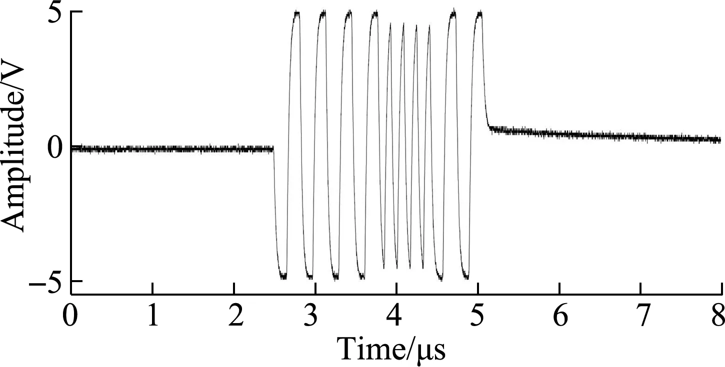
Figs.2(a)and(b)illustrate four-bit BFC excitation signals.The frequencies of low-and high-frequency code elements are 3.2 and 6.4 MHz, respectively.Figs.2(c)and(d)illustrate the coded ultrasonic echo signals reflected from the flat bottom aluminum alloy sample.The center frequency of the ultrasonic transducer is 5 MHz with a bandwidth of 4 MHz.Fig.2 indicates that this type of signal has a longer oscillation and a more complicated waveform than a pulse-excited ultrasonic signal.
(a)

2.2 High-order moment of coded ultrasonic and FRI sampling
Let us assume that the coded echo signalxr(t)reflected from the bottom of the test sample is as follows:
xr(t)=β′x(t)
(9)
The pulse compression signalxm(t0)by extracting the second-order moment of the coded echo signal can then be obtained as follows:
(10)
whereβ′ is the reflection attenuation coefficient andt0is the amount of delay processing for one of the echo signals.
To improve the SNR and time resolution of the coded ultrasonic signal, a pulse compression[19]technique is generally performed on its echo signal using a matching filtering method[20-22], which is a second-order moment method.

Figs.3(a)and(b)present the second-order moment waveforms of Figs.2(c)and(d), respectively.The sidelobe level of the signal that was compressed using the matched filter is still high, because it is difficult to obtain the signal ROI and the accurate parameters of the coded ultrasonic echo signal.To suppress the sidelobes and highlight the mainlobe, a mismatched filter is constructed by adding a window function in the matched filter[24-25]; however, this method increases the mainlobe width and decreases the mainlobe amplitude.

(a)
To overcome the shortcomings of the second-order moment method, a high-order momentxH(t0)of coded ultrasonic echo signals is introduced, which can be expressed as
xH(t0)=[xm(t0)]2nn∈Z+
(11)
If the mainlobe amplitudePH≥ 1 and the sidelobe amplitudePL<1, the mainlobe amplitude of a high-order momentxH(t0)is then maintained or increased and each sidelobe is attenuated.The higher the order 2n, the greater the attenuation.If both the mainlobe and sidelobe amplitudesPH<1 andPL<1, the amplitudes of the mainlobe and sidelobe of the high-order momentxH(t0)are attenuated.As the mainlobe concentrates the main energy of the second-order moment, assuming that the minimum ratio of mainlobe to sidelobe amplitudes is ΔP=PH/PL, the attenuation gradient of the sidelobe is then larger than that of the mainlobe.This has the same effect of enhancing the mainlobe and suppressing the sidelobe.


(a)

(12)
where 2nis the order of the high-order moment;tslis the oscillation start time of the coded ultrasonic echo signal;telis the oscillation end time of the coded ultrasonic echo signal; andt0is the time delay of the processing system.
2.3 FRI sampling method of the coded ultrasonic echo signal
The FRI sampling process of the coded ultrasonic echo signal can be summarized as follows:
1)Generating the coded excitation signalc(t)according to coding rules;
2)Driving the ultrasonic transducer by power amplification to generate the coded ultrasonic detection signalx(t);
3)Obtaining the reflected echoxr(t)from the test object;
4)Obtaining the high-order moment signalxH(t0)from the echo signalxr(t);
5)Performing FRI sparse sampling onxH(t0)to obtain sparse sampling datay[n];


Fig.5 presents the framework of FRI sparse sampling for the coded ultrasonic echo signal.

Fig.5 FRI sparse sampling framework of the coded ultrasonic signal
3 Circuit Design of the Sparse Sampling Framework
To verify the effectiveness and performance of the proposed method, a circuit has been designed.Fig.6 shows the circuit block diagram.

Fig.6 Circuit block diagram of FRI sparse sampling of the coded ultrasonic signal
The circuit includes a code generation module, echo-receiving module, matched filter module, high-order moment convert module, and FRI sampling kernel circuit model.The coded excitation signal is generated using the code generation module for exciting the ultrasonic transducer, and the coded ultrasonic echo signal is pre-amplified and bandpass-denoised using the echo-receiving module.The second-order moment of the echo signal is then extracted using the matched filter module.The high-order moment of the echo signal is further transformed using the high-order moment convert module to generate the ultrasonic pulse stream with its output signal amplified again by a post-amplifier.Finally, the FRI sampling kernel is applied for subsequent data sampling with a uniform interval at a low sampling rate.
Code generation module: An FPGA is used as the control chip to generate a BFC signalc(t); the frequency of the low-frequency code element “0” is set to 3.2 MHz, the frequency of the high-frequency code element “1” is set to 6.4 MHz, and the code length is set to 4 bit; i.e., there are 24coding forms from 0000 to 1111.The ultrasonic excitation chip is used to amplify the BFC signal into a high-energy-coded excitation signal with an amplitude of ±60 V, exciting the ultrasonic transducer to generate a coded ultrasonic signal.
Echo-receiving module: The preamplifier circuit consists of the operational amplifier, which is used for impedance matching and preamplification of the coded ultrasonic echo signalxr(t).Preamplification aims to adjust the amplitude of the coded ultrasonic signal in a proper range to fit subsequent signal processing.The second-order Butterworth bandpass filter circuit consists of the operational amplifier.The central frequency of the passband is set to 5 MHz, the bandwidth is set to 4 MHz with the passband attenuation set to-3 dB, and the stopband attenuation is set to-40 dB.
Matched filter module: This module divides the echo signal into two signals and delays one of them.The delay circuit consists of a second-order Bessel lowpass filter implemented with the passband cutoff frequency set to 10 MHz, passband attenuation set to-3 dB, and the stopband attenuation set to-40 dB.Because of the large group delay of the Bessel filter, the echo signal can be delayed by hundreds of nanoseconds.The two signals are connected to the four-quadrant multiplier, and the output of the multiplier is connected to an implemented integral circuit.The second-order moment of the coded ultrasonic signalxm(t0)is then obtained.
High-order moment conversion module: The second-order momentxm(t)is connected to the four-quadrant multiplier for multiplication, and the result of the multiplication is its high-order moment.More multipliers are required for higher orders.The high-order moment of a coded ultrasonic echo signal is finally constructed into an ultrasonic pulse stream signalxH(t0)by gain adjustment.
Part of the FRI sampling kernel hardware circuit is implemented using a Chebyshev lowpass filter to form a Fourier series coefficient screening circuit for approximation, which then directly samples it using the FRI sparse sampling circuit.According to the characteristics of the input signal and results of the subsequent parameter estimation algorithm, the conditions for a sampling kernel to be satisfied are determined.After the input signal passes through the FRI sampling kernel circuit, sparse sampling can be performed on it at its ROI, and the major parameters can be estimated using the sparse-sampled data through the parameter estimation algorithm.
4 Experimental Results and Analysis
An experimental platform was established to verify the effectiveness of the proposed method for pulse stream forming and FRI sampling, as shown in Fig.7.In the experiments, a 4-bit BFC ultrasonic detection signal was adopted, and a test signal was applied to an aluminum alloy sample to obtain the flat bottom echo.The high-order moment of the coded ultrasonic echo signal was then obtained using the pulse stream construction circuit.The ultrasonic pulse stream signal was processed using the FRI sampling kernel circuit to obtain the FRI sampling kernel output signal.Finally, the signal was sparse-sampled at a low sampling rate with uniform intervals to obtain the sparse sampling data.

Fig.7 Experimental platform
In the experiment, a T/R immersion normal ultrasonic transducer with a central frequency of 5 MHz and bandwidth of 4 MHz was used.Water was used as a coupling medium.The thickness of the aluminum alloy sample was 20 mm, the frequency of the low-frequency code element “0” was set to 3.2 MHz, the frequency of the high-frequency code element “1” was set to 6.4 MHz, and the code length was set to 4 bit.
Using the coded ultrasonic signal 0010 and 0101 as examples, Figs.8(a)and(b)show the initial pulse and bottom echo of the coded ultrasonic signals 0010 and 0101.Figs.8(c)and(d)show the pulse stream, FRI sampling kernel output, and FRI sampling points of the two coded signals, respectively.Figs.8(e)and(f)present a comparison of the pulse stream and the estimated signal with the parameters estimated using the FRI sparse sampling data, respectively.According to the Nyquist-Shannon sampling theorem, the A/D sampling rate of the coded ultrasonic detection signal needs to be no less than 12.8 MHz.In the experiment, the number of pulse echoes isL1=2, the signal duration isτ1≈8 μs, and the local maximum innovation rate of the ultrasonic pulse stream is ROI1=2L1/τ1≈0.5×106, that is only 4% of the conventional sampling frequency.The high-order moment in this experiment was the twelfth one.Clearly, the mainlobe amplitude of the coded ultrasonic echo signal was greatly increased and the sidelobe amplitude was greatly attenuated.An annihilating filter algorithm was used to estimate the signal peak amplitude and time of flight of the pulse stream using the sparse-sampled data.

(a)


(a)
The converted pulse stream signal could be FRI sparse-sampled, and the amplitude and time of flight of the high-order moment signal could be accurately estimated using the sparse-sampled data.The maximum error of the amplitude was 9.324%.This may be due to the saturation phenomenon when the amplitude of the ultrasonic pulse stream signal exceeds the rated value of analog devices.The maximum error of the time of flight was 0.031%.The FRI sparse sampling frequency was performed at the local maximum innovation rate of the high-order moment pulse stream signal, which was 0.5 MHz.Therefore, the sparse sampling rate was considerably lower than that using the conventional Nyquist sampling method, and the amount of sampling data was considerably reduced.
At the same time, the echo pulse amplitude of the original coded ultrasonic signal is compared with the echo pulse amplitude of the high-order moment pulse stream.If there are multiple echoes in one detection, the minimum amplitude value is taken, as shown in Fig.10.When the noise level is constant, extracting the high-order moment pulse stream can improve the SNR by increasing the echo amplitude of the detection signal.

Fig.10 Comparison of echo amplitudes
5 Conclusions
1)In response to the problem of coded ultrasonic FRI sparse sampling, this study proposed a novel framework by converting the coded ultrasonic echo into a pulse stream to satisfy the requirements of FRI sparse sampling.
2)A circuit has been designed to implement the proposed framework using a high-order-moment-based converting method of twelfth to convert the signal.
3)Experiments have been performed on an aluminum alloy sample using a binary frequency-coded ultrasonic signal with an encoding length of 4.Experimental results show that the coded ultrasonic signal can be FRI sparse-sampled using a high-order-moment-based converting method, and the amplitude and the time of flight of the echo signal can be estimated using the sparse-sampled data with maximum errors of 9.324% and 0.031%, respectively.
4)The sparse sampling rate was 0.5 MHz in the experiments, which is considerably lower than the conventional Nyquist sampling rate of at least 12.8 MHz.
杂志排行

Journal of Southeast University(English Edition)的其它文章
- Statistical analysis of nondestructive testing results of cast steel joints in civil engineering structures
- Novel sensitivity analysis method and dynamics optimization for multiple launch rocket systems
- Detection of solar radio burst intensity based on a modified multifactor SVM algorithm
- Metrics analysis of tactile perceptual space based on improved NMDS for leather textures
- Short-term traffic flow prediction with PSR-XGBoost considering chaotic characteristics
- Contract stability and default risk control of pig farming in the company and farmer mode