Adaptive robust feedback control of moving target tracking for all -Electrical tank with uncertainty
2022-04-19YuzeMaGuolaiYangQinqinSunXiuyeWangZongfanWang
Yu-ze Ma, Guo-lai Yang, Qin-qin Sun, Xiu-ye Wang, Zong-fan Wang
The School of Mechanical Engineering, Nanjing University of Science and Technology, Nanjing, 210094, China
Keywords:Mechanical system Tank stability Uncertainty Road excitation Adaptive robust feedback control
ABSTRACT A moving target tracking control problem for marching tank based on adaptive robust feedback control scheme is addressed. A series of preparations is needed for tank gun before shooting a target, the purpose of this paper is to design a control system to fulfill two requirements in this process: the turretbarrel system of tank needs to be adjusted from off-target position to command position and point to the moving target stably when there are strong uncertainties (modeling error, uncertain disturbance with unknown boundaries and road excitation) in the system. Considering the characteristic of coupled interaction, the first thing we do in this paper is to build a coupled analysis model of turret - barrel system with uncertainty term in state-space form.Second,an adaptive robust feedback control scheme is proposed by adding adaptive law to overcome the uncertainty. Third, multi-body dynamics software is used to establish the mechanical mechanism of the tank, and DC-motor module is established in SIMULINK environment,thus the target information and tracking error of the control system is collected and transferred, the gear-ball screw is derived directly by the output torque of the DC-motor module.Finally, the control system and the 3D model are combined together by means of RecurDyn/SIMULINK co-simulation, the turret-barrel system of tank can approximately track the moving target in a certain range. With the adaptive robust feedback control, the target action is completely followed when the target location is constantly changing.
1. Introduction
Stable tracking control is the necessary condition of automatic firing process of tank weapon and precondition for improving the firing accuracy of artillery [1]. The existing tank tracking system generally adopts electro-hydraulic servo control, which has the disadvantages such as slow response, low efficiency and low control accuracy. The all-electric structure has the advantage of low maintenance cost while overcoming the above disadvantages, and this allows the whole tracking control system to be powered by electricity. However, the appearance of all-electric mechanical structure makes the nonlinearity of tracking system (friction,disturbance and modeling error)more complicated,researchers all over the world to seek a breakthrough. Thus, an adaptive robust control method for strong nonlinearity and uncertainty is required for the tank tracking system.
Tank tracking system is a kind of automatic control system,which is used to control the angular displacement or velocity of the turret and barrel, it must automatically, continuously, accurately reproduce the changing rules of input instructions to ensure the firing requirements of moving tank. At present, the existing tracking control strategies are mainly designed for the linear and weak nonlinear dynamics system, such as PID control and LQR control in particular[2-5].All-electric tracking control system is a multivariable and high order non-linear complex system with significant cross-couplings, meanwhile, this system is not only required to respond quickly with high dynamic and static accuracy,but also needs to have insensitivity to parameter changes and disturbances. That is to say, the tank tracking system urgently excepts a coupled control method that can deal with those uncertainties.
Over the past decades, some scholars began to adopt more advanced control methods to deal with the tracking control problem like adaptive robust control [6-9], sliding mode control[10-13]and even intelligent control[14].Although there are some novel and outstanding contributions to tank tracking control in these researches, however, the modeling of the system has been simplified without exception to an uncoupled, approximate analytical model, because the control objectives cannot be accurately described. At the same time, the conventional control methods based on error cannot meet the requirements of increasing accuracy. As a pioneer work, this paper presents an adaptive robust feedback control based on the coupled tracking system model, and finally the control method is applied to the dynamic virtual prototype.
Scholars in the field of control methods for systems with uncertainty have made some progress in recent years [15-17]. As an outstanding contribution to uncertain mechanical systems, Chen[18-29] recently proposed a combination of several control methods to further improve system control performance. Specifically, in order to enhance the robustness to uncertainties and disturbances, constraint following control, feedback control and robust control are adopted to stabilize the system with unknown boundary uncertainties [30]. However, the previous control methods often underestimate the error and uncertainty between the real controlled object and the analytical model. The turret -barrel tracking system is disturbed by uneven road conditions,friction and contact collision between two mechanical components, these nonlinear factors are difficult to model accurately in analytical model. In this context, we introduce an uncertainty bound ℘to measure the impact of the uncertainty with unknown boundary,along the way,an adaptive strategy is used to ensure that the turret-barrel system can track the time-varying target position stably under complex disturbance conditions.
The work of this paper mainly consists of five parts. In the second section, a coupled dynamic model based on the tank tracking system,which is in state-space formed,is established as a reference model in the control strategy, the rotation of turret and barrel will undoubtedly affect each other to some extent. In the third section,with regard to the problem of aiming while the tank is marching, the multi-body dynamics simulation environment is established by three-dimensional modeling,which can completely restore the real battlefield environment, including the undulating road conditions, collision and friction between gears, nonlinear characteristics of suspension system and the target motion model of enemy tanks moving in opposite directions.In the forth section,the uncertainties in the model is taken into account to present the whole pointing tracking system in state-space form. In the fifth section, an adaptive robust feedback control method for tank tracking problem is proposed by adding adaptive law to overcome the uncertainties. By adding some compensation terms and adaptive terms, the turret - barrel system can approximately track the moving target in a certain range. In the end, the adaptive robust feedback control method is combined with the three-dimensional model in the form of RecurDyn/Simulink co-simulation. At this point, uncertainties and nonlinear factors can be fully described,and the turret barrel system is controlled to be practically stable.
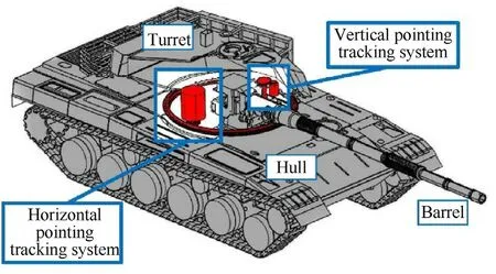
Fig.1. Barrel - turret tracking system of all-electrical tank.
2. Analytical dynamic model of marching tank with tracking control system
The function of turret-barrel tracking control system is to make the tank barrel and turret tracking the target stably. As shown in Fig. 1, the system consists of a swing part (turret) and a pitching part (barrel) attached to the pedestal (hull). The actuator of the tracking control system consists of a DC motor, a reducer, and a mechanism that converts the transmission mode (such as wormgear and ball screw). The dynamical model of the tank with control system can be described as [31]:


where t∈R is the time, φ(t)∈Ris the angular positions of the turret respect to the hull, φ(t)∈R is the angular positions of the barrel respect to the turret,F(t)∈R are the torque inputs,f(t)∈R are the external disturbances other than the active moments,mare the masses of turret and barrel,Lare the radius,and~g is the gravitational constant.
2.1. Dynamic model of horizontal pointing tracking system
The horizontal pointing tracking system includes the turret,DC motor and transmission gear set (saddle ring gear and race ring gear),the stator of the DC motor is fixed to the inside of the turret,the race ring gear is bolted to the tank chassis,when the system is in operation, the DC motor and saddle ring gear rotate with the turret in the horizontal direction simultaneously.The transmission schematic diagram and installation location of the motor-gear set system are shown as Fig.2.The dynamical model of the motor can be expressed as [20]:
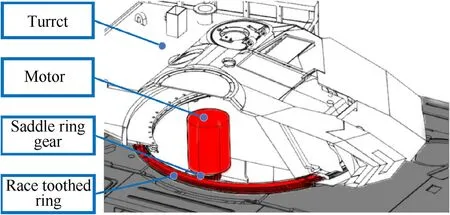
Fig. 2. Horizontal pointing tracking system.

where J. is the moment of inertia of the motor, τ(t)∈R is the motor torque, τ(t)∈R is the gear input torque, Dis viscous damping coefficient of the motor,ω(t)∈R is the angular velocity of the motor,cand care the constrains of the motor torque and the electromotive force, Ris the overall resistance of the armature circuit,u(t)∈R is the control input voltage.Due to the small value of armature inductance, armature lag effect is neglected.
Since there is backlash nonlinearity between the motor gear and the transmission gear, we consider adding a parameter f(t)∈R to represent the error in the transmission process, the relationship between the gear output torque F(it is the input torque of the turret system precisely as Eq. (1)) and the gear input torque τ(t)can be expressed as

Taking Finto Eq. (1) and we get the dynamic equation of the horizontal pointing tracking system

Remark 1. On the basis of the turret tracking system model Eq.(1), the influence of motor and transmission system is considered.This means that there must be backlash nonlinearity in the system,so far we have derived a nonlinear model including motor, gear transmission system and turret.
2.2. Dynamic model of vertical pointing tracking system
DC motor speed regulation system is also adopted on the vertical pointing tracking system, the difference is the rotation of the barrel in vertical direction using ball screw pair for the transmission.One end of the lead screw is fixed to the cradle of the tank,the stator of the DC motor is connected to the turret by bearings.The transmission schematic diagram and installation location of the electric cylinder are shown as Fig.3 and Fig.4.The dynamics of the electric cylinder can be described as [32]:
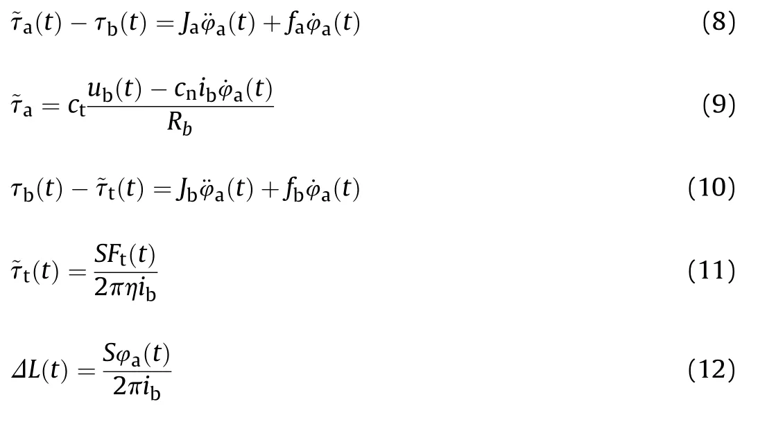
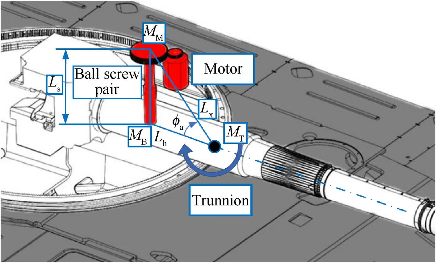
Fig. 3. Vertical pointing tracking system.
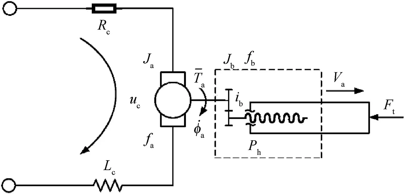
Fig. 4. Transmission schematic diagram of the electric cylinder.
where ~τ(t)∈R is the electromagnetic torque of the motor shaft,τ(t)∈R is the output moment of motor, φ(t)∈R is the output rotation angle of motor,cis the electromagnetic torque coefficient,u(t)∈R is the input voltage of the armature winding, ~τ(t)∈R is the output moment of electric cylinder;Jis the moment of inertia of the motor shaft,Jis the moment of drive system,fis the viscous fiction coefficient of motor shaft,fis the viscous fiction coefficient of drive system; F(t)∈R is the load force, S is screw lead, η is the mechanical transmission efficiency, iis transmission ratio, and ΔL(t)∈R is the stretching length of piston road.
Structural schematic diagram of the erecting mechanism is shown in Fig. 3, which describes the geometric relationship and installation position of the electric cylinder, barrel and trunnion.Among them, the trunnion is the rotation center of the barrel in vertical direction.The displacement of pistion rod can be expressed by


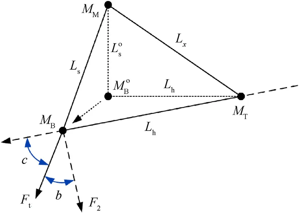
Fig. 5. Structure diagram after the action of the electric cylinder.

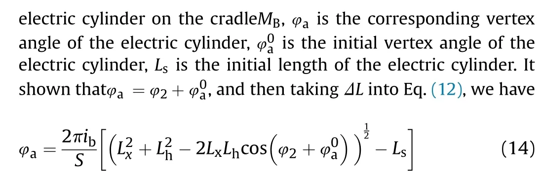
with Eq. (8) to Eq. (10), we have

Fig.5 further describes the changes of the mechanical structure of vertical pointing tracking system after the action of the electric cylinder. When the system works, Mmoves toM, the overall length of the electric cylinder changes from Lto L(the description mode of Lis just to reflect the change of the overall structure of vertical pointing tracking system),b and c are respectively the angle between the supporting force direction of the electric cylinder and the central axis of the cradle in vertical and parallel directions.Thus the torque input on the barrel Fcan be described as
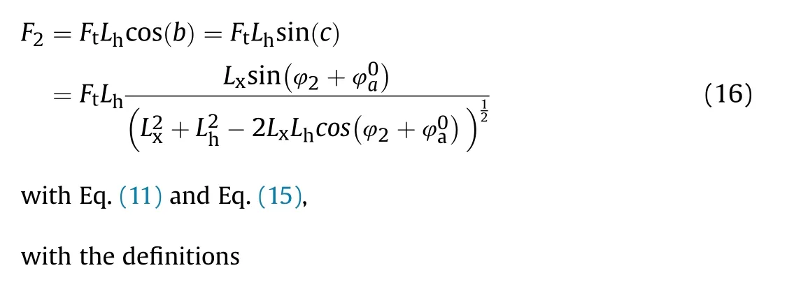


Thus we get the dynamic equation of the vertical pointing tracking system

Remark 2. The dynamic equation of the vertical tracking system is deduced from the dynamic equation of the electric cylinder system Eq. (8) to Eq. (12) and the position transformation relation of the mechanical structure of the vertical tracking system Eq.(13)to Eq.(16),thus the vertical stabilization system is coupled with the electric cylinder mechanism,with complex nonlinearities attached.
3. Multibody dynamics model of marching tank with tracking control system
A tank with tracking control system mainly involve three kinds of movement: driving movement, turret adjusting movement and barrel adjusting movement. The uncertainty and nonlinearity of model can be easily characterized through the research method of virtual prototyping technology, at the same time, co-simulation between the multi-body dynamics model and control system can conveniently be realized [31,33,34]. The dynamics model of the tank is shown in Fig. 6.
3.1. Multi-body dynamics modeling of suspension system
The elastic element of the tank suspension system is torsion bar shock absorber, the impact energy of torsion bar spring is consumed because of the torsion deformation,thus the vibration of tank is attenuate.
Suppose the rotation angle of the torsion bar spring isΘ = ΣΣ,the vertical elastic load Fof the torsion bar can be expressed as follows
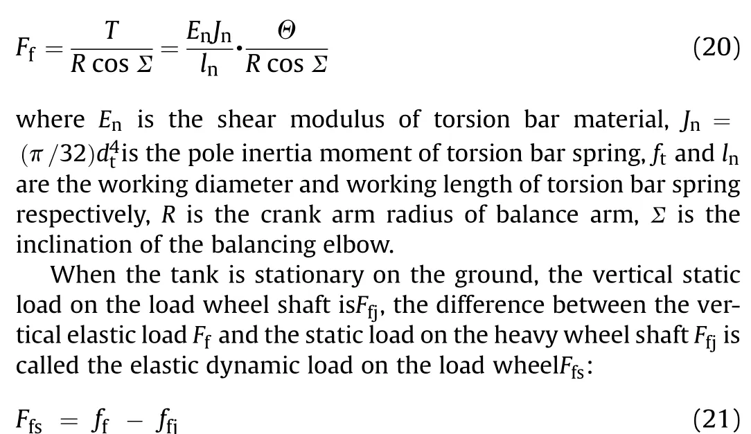
The relation between the elastic dynamic load on the load wheel shaft fand the working distance of the load wheel f is called suspension characteristic. The torsion bar suspension has the characteristic of bidirectional gradual rise, the slope of the suspension characteristic is called the suspension stiffnessK:
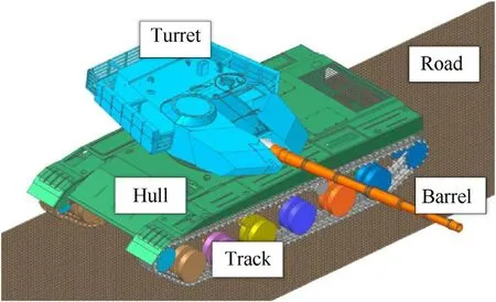
Fig. 6. Multibody dynamics model of the tank.

It can be seen that the stiffness of torsion bar suspension Kis a nonlinear parameter that changes with the inclination of the balancing elbow Σ and the working distance of the load wheelf.Remark 3. Suspension stiffness is a nonlinear function that changes with the position and angular attitude of tank loading wheels.In the modeling process of multi-body dynamics software,the stiffness and damping characteristics of the suspension system is defined by the programming of the suspension stiffness function Eq. (22).
3.2. Roughness model of three-dimensional road
When a tracked vehicle is moving, the fluctuation of road surface is the main factor that causes the tank’s vibration. The road roughness varies with the geometric contour of the road surface and it is a typical random process in time domain and space domain,so when we need to analyze the dynamic response of the system,we need to reconstruct the road roughness in time or space based on the power spectral density function.
Considering the difficulty of measuring the actual random road roughness and the actual driving conditions of tank weapons, the harmonic superposition method is used to transform the statistical law in frequency domain into time domain and space domain,which is appropriate to analyze the influence of different undulation degree of road on muzzle vibration. The pavement roughness function can be superposed by a series of random phase sine functions, which can be expressed as two-dimensional [35]:
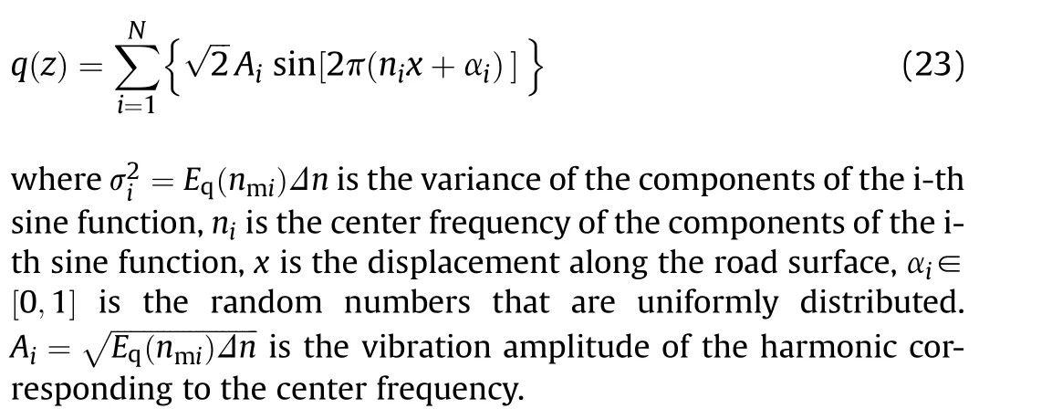
In addition, the random phase angle of the roughness function of three-dimensional road is different, which causes the left and right tracks to receive different excitation from the ground. By extension, the three-dimensional road roughness function can be expressed as
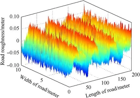
Fig. 7. D level profile in three-dimensional plot.
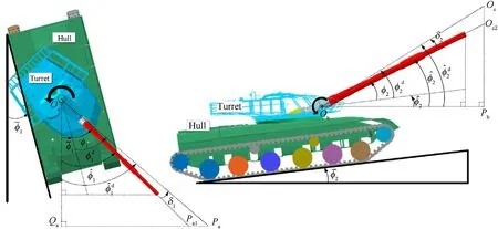
Fig. 8. Schematic diagram of target angles and actual angles.

y is the displacement perpendicular to the road surface.
According to Eq. (24)and Eq. (25), the 3D pavement roughness calculation program is prepared as shown in Fig.7,and joint stitch method was used to generate road file that could be read by RecurDyn.
Remark 4. We chose random three-dimensional road and modeling uncertainty as the influence elements affecting the tracking accuracy of the tank, because the accuracy of the model and the cost of calculation time are comprehensively considered,and those elements can be fully reflected in the dynamics software of the multi-body system, so contact and friction are not considered.
4. Formulation of moving target tracking problem for marching tank
The calculation of the position relationship between friend and foe on the battlefield needs to be calculated out in the unified coordinate system,the coordinate system in the tank tracking system includes coordinate system of the groundO, coordinate system of the hullO,coordinate system of the turretO,coordinate system of the laser sight Oand coordinate system of the targetO, so the relative rotation angles of the turret, hull and barrel can be calculated from the relative motion of the coordinate system(modern tanks are generally equipped with a variety of gyroscopes).

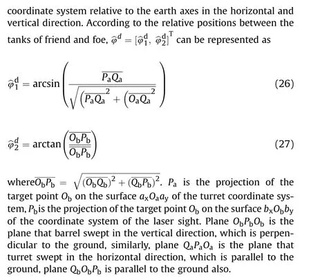
Remark 5. The determination of the coordinate system is only used to measure the relative rotation angle between the coordinate systems, and the position of the origin of the coordinate system does not affect rotation angle on the axis for two coordinate systems,provided that the calculated axes are not shifted.
According to the relationship between the actual angle and the target angle in Fig. 8, the tracking error can be expressed as:
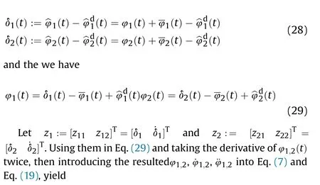
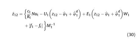

with the definitions





5. Adaptive robust control for pointing tracking
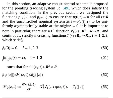
Now, we refer to the discussion of the bounding condition for the uncertain portions Δp and ΔG in system Eq.(49).Δpand ΔG can be decomposed as
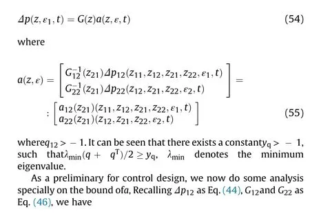

Let

We then can rewrite Eq.(56) as

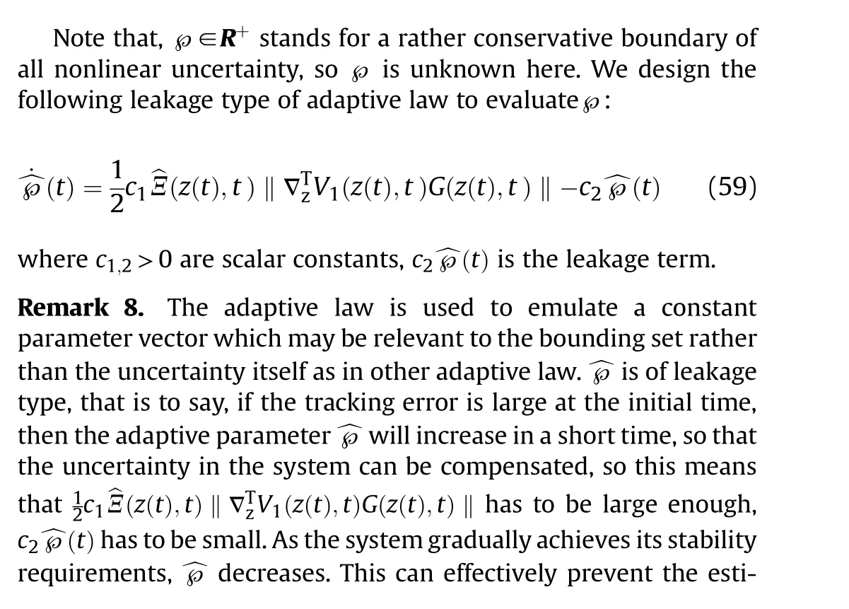

Based on this adaptive law, we proposed the following class of adaptive robust feedback control for the system Eq. (49) [36,37].

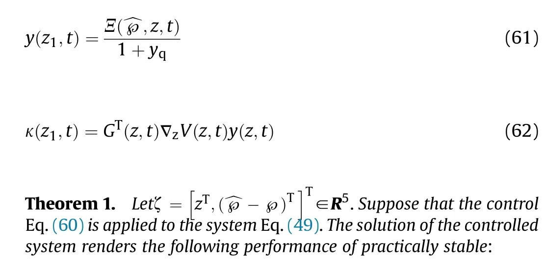
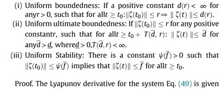
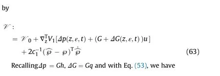

with Eq. (59) and Eq. (60), if ‖κ‖>ε, we have

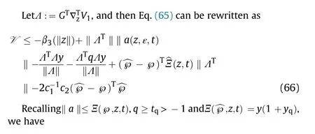

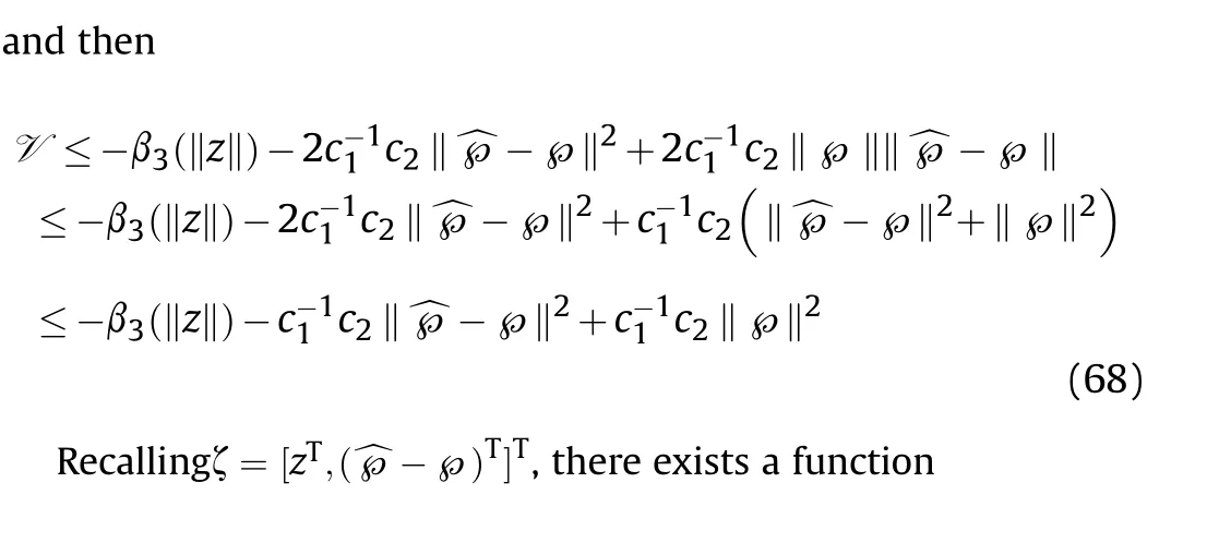
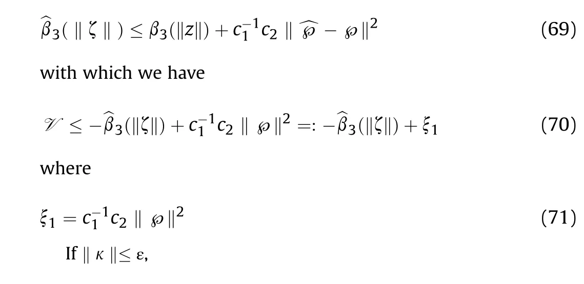

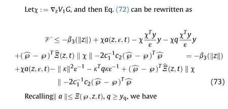

RecallingΞ(^℘,z,t) = y(1 + y), we have

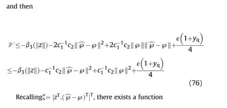
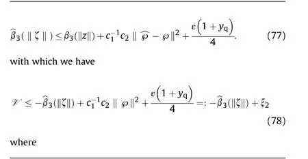
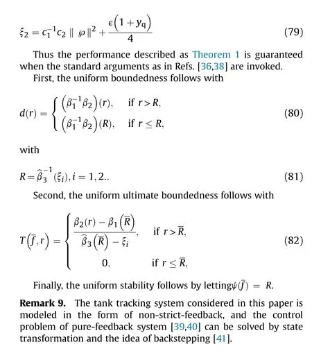
6. Control procedure for co-simulation of tracking system
The purpose of this paper is to design an adaptive robust feedback control method for the tank tracking system in the cosimulation environment, and there are a variety of nonlinearities in the system. The whole simulation process (shown as Fig. 9) can be simply sorted into the following links:
(i) Clarify the position relationship between friend and foe in the whole coordinate system, then the horizontal/vertical direction target angle ^φand error angle δare calculated in real time and transmitted to the tracking system separately.
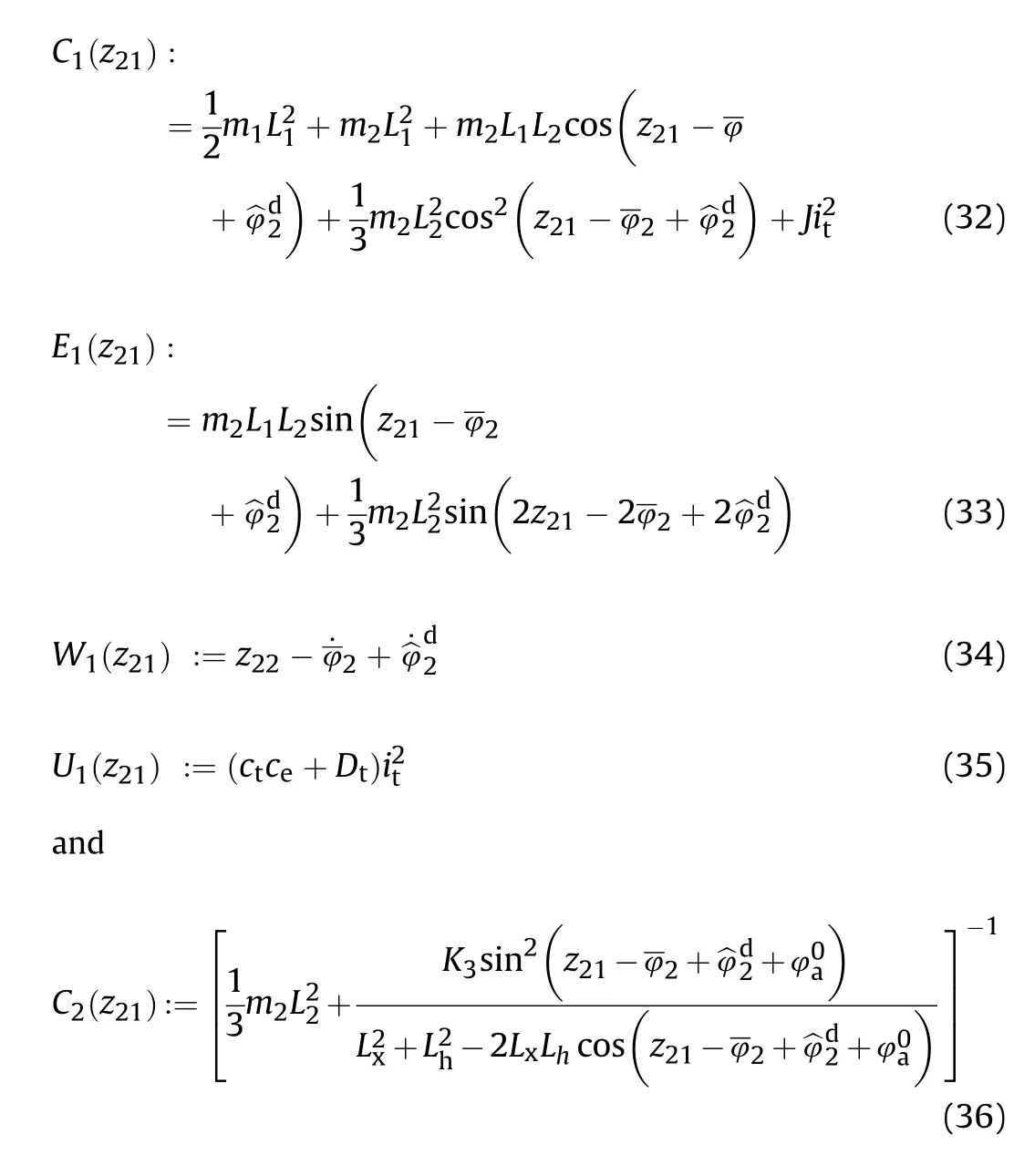
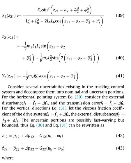
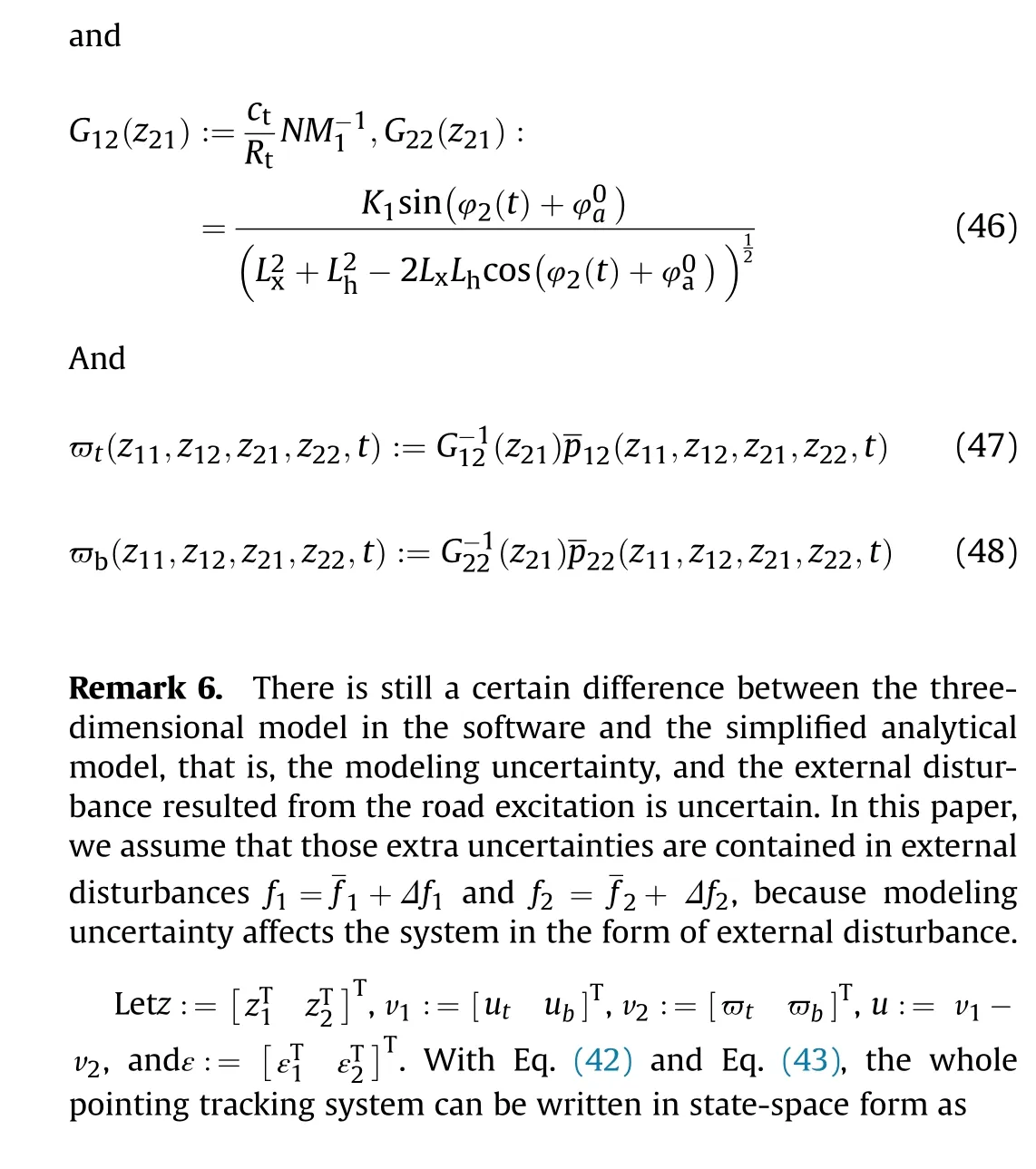
(ii) Establish the analytical model of horizontal/vertical tracking system (includes the execution mechanism like DC-motor and electric cylinder) as Eq. (7) and Eq. (19), then rewrite the analytical equations in state-space form as Eq. (49).

(iv) Design the adaptive law ^℘(·) based on the bounding condition of the uncertain portionsΔp.
(v) Design the adaptive robust control u(·)as Eq.(60).The input of the model-based control system are tracking error δand tracking target angle ^φ,the output are the control voltage uand uof the DC motors.
(vi) Establish the DC-machine blocks in simulink environment,this DC-machine represent the motor of tracking system in horizontal direction and the motor of electric cylinder in vertical direction, respectively, which is different from the analytical model established at the beginning of this paper at the level of representational meaning.
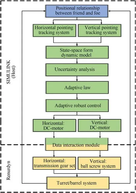
Fig. 9. Simulation process.
(vii) The output torque of the motor blocks are transmitted through the information interaction module, and applied to the gear set in RecurDyn, the turret/barrel system operates under the transmission of the gear set, and begins to track the target as the tank is on the move, at the same time the tracking error is fed back to the control system.
7. Simulations
7.1. Initial conditions of tracking control system
The purpose of tracking control system is to realize the tracking of moving targets continuously on the battlefield, The first task of tracking the target is to determine the position between our tank and enemy targets.
Assume that the relative relationship between the two sides of the battlefield at the beginning of simulation is shown in Fig.10.The target tank is moving in the direction of Vat the speed of 35 km/h, and Vis parallel to the planeOQP, which is belong to coordinate system of the groundO.The distance between friend and foe on the horizontal projection plane has been marked in the figure, with a height difference of 140 m.
7.2. Parameters selection
Take a certain tank as the research object.For the simulation,we choose mass of turretm= 5200.00kg, mass of barrelm=2088.15kg, turret rotation radiusL= 1.05m, barrel rotation radiusL= 5.12m, gravitational accelerationg = 9.8m/ s.
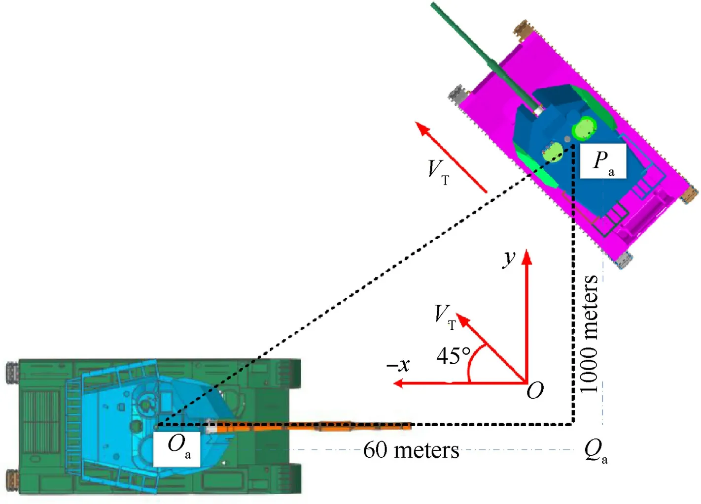
Fig.10. The positional relationship between friend and foe.
The parameters of the analytical model in the control law are consistent with those of the multi-body dynamics model. For the horizontal tracking control system, J = 0.0021kg·m, D=0.0088N·m·s/rad,which includes the system modeling error,i=13.14, c= 1.55N·m/A,c= 20.7725V·m/A. For the vertical tracking control system,J=0.495kg·m,J=0.012kg·m,f=0.0153+0.00153sin(10t)N·m·s/rad,f=0.0063N·m·s/rad,c=2.7× 10N·m/A. The range of barrel motion in the vertical direction is-5~+18,we choosei=3,S =0.2m,L=0.7m,L=0.5m, L= 0.86m,φ= asin(0.81).
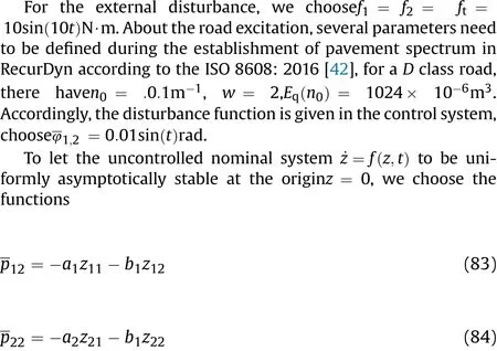

The parameters of proposed controller are given asβ = 100,c= 15,c= 800. To compare the control effects, we choose parallel PID control as the comparison method, the formula of compensator is as follows:
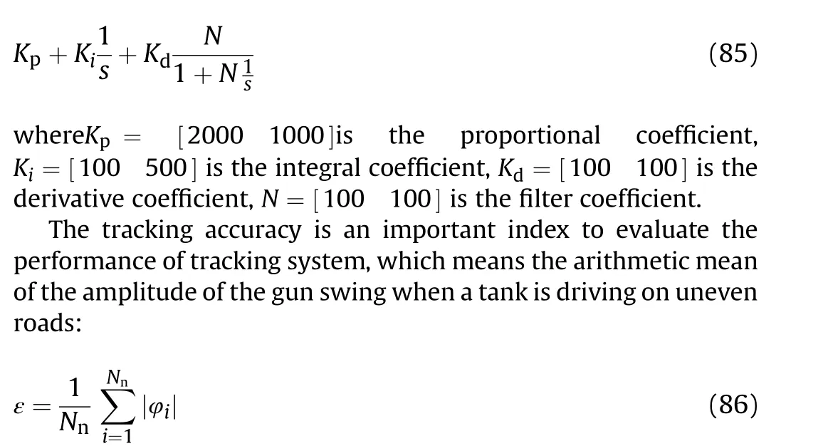
where Nis the total number of sample points, φis the horizontal and vertical angular displacement of the gun which are obtained by sampling.
7.3. Simulation results
The simulation results are shown as Fig. 11 to Fig. 14. The disturbance angle of the hull is shown as Fig.11,it can be seen that the interaction between the track and the ground causes violent disturbance on the hull in both the horizontal and vertical directions, the shaking of the hull will eventually be passed to the turret and barrel,which has a significant influence on the stability effect of tracking system.
Since the enemy target is traveling in the opposite direction,the target angle of the tracking control system on horizontal direction is increasing, change in the target angle on horizontal direction is unconspicuous.The rotation angle of the turret and barrel relative to the ground coordinate system are shown in Fig. 12(a) and Fig.12(b).It can be seen that the horizontal tracking system tracked the target within 2.5 s, with the proposed control; the vertical tracking system tracked the target within 2 s,while PID control has great inferiority in tracking speed and stable accuracy.Fig.12(c)and(d) present the tracking error of the system, it can be seen that compared with PID control, proposed control can make the tracking error δclose to 0 faster.we summarize the data after 4 s(at the fourth second the system becomes stable) in Table 1.
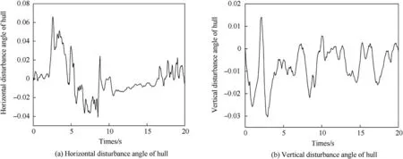
Fig.11. Disturbance angle of hull.
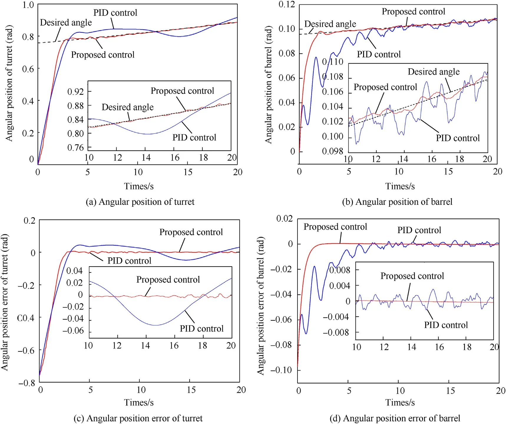
Fig.12. Angular position and error.

Table 1 The results.
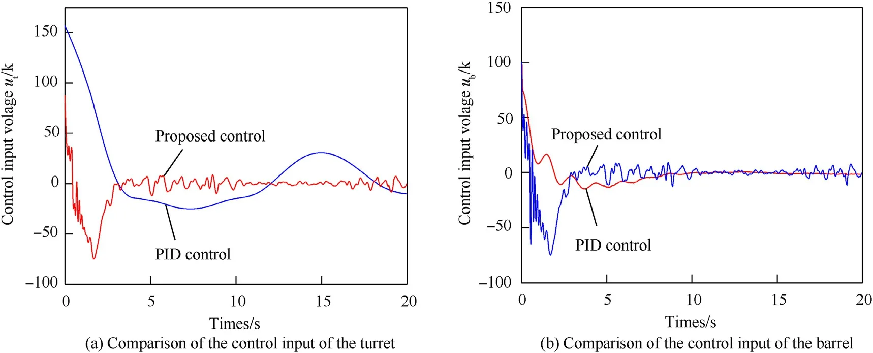
Fig.13. Control input of the tracking system.
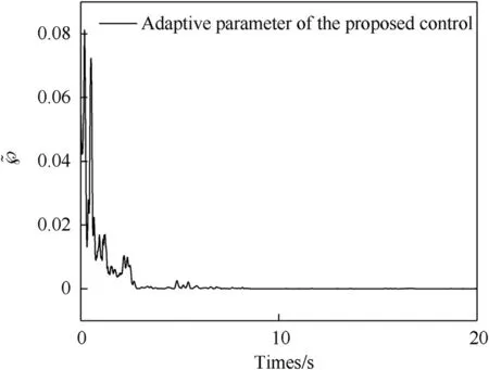
Fig.14. Adaptive parameter ~℘history.
It can be seen from Table 1 that the tracking accuracy of the two controllers is close to the requirement in a certain standard,but the difference in stability is clear, tanks with adaptive robust feedback control have higher tracking accuracy; meanwhile, the extreme value and RMS(root-mean-square)of the PID control error are both three times of proposed control, these are all representations of better tracking effect.
Fig.13 present the control input of the DC-motor, the suppression effect of PID control on nonlinear factors is not as good as that of proposed control,excessive control input results in overshooting and violent oscillation of the system. The variation rule of ~℘is shown in Fig.14, ~℘increases rapidly to the extreme value ~℘=0.081 to allow the control system to adapt to sudden uncertainties.Then ~℘is going to go negative with its leakage, which means the system gradually stabilized.
8. Conclusion
In this paper, we solve the problem of moving target tracking control for the marching tank by using the adaptive feedback control.The model-based control algorithm has a high requirement on the accuracy of the dynamic model,we refined the model of the tracking system and added three-dimensional models of motors and cylinders to the multi-body dynamics environment, the analytical model of the electric mechanism is plugged into into the analytical model of the tracking system, the horizontal turretmotor system and vertical barrel-electric-cylinder system are formed. Complex systems are bound to carry with a variety of nonlinear and bounded uncertainties, and the bound is unknown.To keep the control system stable, an adaptive robust feedback method is designed to compensate the errors of the tracking system. As a result, the pre-specified constraint is followed closely. It paves an adaptive way for tracking control, which means that the parameters can be adjusted by the system under the complex disturbance, it exactly makes up for the complex environmental influence on the battlefield.We believe this article pave a new way for the tank tracking control problem, the state-space model of barrel-turret system makes the adaptive robust feedback method have a better performance. Future explorations include the analytical model of the tank tracking system and the control method which is more suitable for the tank system.
No conflict of interest exits in the submission of this manuscript,and manuscript is approved by all authors for publication. I would like to declare on behalf of my co-authors that the work described was original research that has not been published previously, and not under consideration for publication elsewhere, in whole or in part. All the authors listed have approved the manuscript that is enclosed.
This work was partially supported by the Natural Science Foundation of Jiangsu Province (Project no. BK20180474), the Natural Science Foundation of China (Project no. 51805263, no.51705253, no.11572158) and the National Defense Basic Scientific Research program of China (Grant no. JCKY2017208A001).
杂志排行
Defence Technology的其它文章
- Research on DSO vision positioning technology based on binocular stereo panoramic vision system
- Dynamics of luffing motion of a hydraulically driven shell manipulator with revolute clearance joints
- Blast performance of layered charges enveloped by aluminum powder/rubber composites in confined spaces
- Chemical design and characterization of cellulosic derivatives containing high-nitrogen functional groups: Towards the next generation of energetic biopolymers
- Applicability of unique scarf joint configuration in friction stir welding of AA6061-T6: Analysis of torque, force, microstructure and mechanical properties
- Multi-area detection sensitivity calculation model and detection blind areas influence analysis of photoelectric detection target
