Blast performance of layered charges enveloped by aluminum powder/rubber composites in confined spaces
2022-04-19JunLiWeiingLiJixinYuWeiXioHeyngXu
Jun-o Li , Wei-ing Li ,*, Ji-xin Yu , Wei Xio , He-yng Xu
aZNDY of Ministerial Key Laboratory, Nanjing University of Science and Technology, Nanjing, 210094, China
b School of Chemical Engineering, Nanjing University of Science and Technology, Nanjing, 210094, China
Keywords:Confined explosion Aluminum powder/rubber composites Layered charge Blast parameters
ABSTRACT A layered charge composed of the JH-2 explosive enveloped by a thick-walled cylindrical casing (active aluminum/rubber and inert lithium fluoride/rubber composites) was designed and explosion experiments were conducted in a 1.3 m3 tank and a 113 m3 bunker. The blast parameters, including the quasistatic pressure (ΔpQS), special impulse (I), and peak overpressure (Δpmax), and images of the explosion process were recorded,and the influence of the Al content(30%and 50%)and Al particle size(1,10, and 50 μm) on the energy release of aluminum/rubber composites were investigated. The results revealed that the use of an active layer increased the peak overpressure generated by the primary blast wave, as well as the quasistatic pressure and special impulse related to fuel burning within tens of milliseconds after detonation.When the Al content was increased from 30%to 50%,the increases of ΔpQS and I were not obvious, and Δpmax even decreased, possibly because of decreased combustion efficiency and greater absorption of the blast wave energy for layers with 50% Al. Compared with the pure JH-2 charge, the charge with 1 μm Al particles produced the highest Δpmax, indicating that better transient blast performance was generated by smaller Al particles. However, the charge with 10 μm Al particles showed the largest ΔpQS and I, suggesting that a stronger destructive effect occurred over a longer duration for charges that contained moderate 10 μm Al.
1. Introduction
With the development of defense systems, important military targets (e.g., ships and underground fortifications) composed of confined or semi-confined spaces have become increasingly solid.Earth-penetrating weapons, such as thermobaric ammunition[1-4], have been rapidly developed to destroy these targets.Traditional thermobaric explosives often contain metal fuels,which can react with the oxygen and detonation products,generating the heat in a secondary combustion after the detonation of the main charge.Owing to the high heat release from sustained combustion after detonation, Al is the most widely used metallic fuel in thermobaric explosive [5-8]. In general, both its own characteristics and the external environment affect the reaction of Al. Al with relatively large particle sizes often shows a low reaction rate,while relatively small Al is susceptible to oxidation,leading to a decrease in the activity. To improve the heat releases and combustion efficiency of Al in thermobaric explosives, many strategies have been developed.
A separate group of explosives with enhanced combustion efficiently and improved blast parameters are layered charges,which were originally described in US patents [9], and they have attracted increasing attention [10-13]. Such charges comprise a reactive metal, an oxidizer, and a binder, providing an increased thermal effect of the explosion and a relatively high pressure lasting for up to tens of milliseconds.Clemenson[10]investigated the reactivity of aluminum warhead casings using explosive initiation experiments and measured the transient and quasi-static pressure of charges with different alloy compositions and casing geometries.Zhang et al.[11]experimentally studied the dynamic fragmentation and blast effect of a reactive material comprising the micro-sized composite 10 Al+MoOby the explosive loading technique. A layered spherical charge structure composed of a high explosive and a cylindrical casing made of aluminum powder was designed in Ref. [13], and the attenuation of the blast wave and combustion behavior of the aluminum powder were studied.
The general idea behind the design of layered charge was that upon detonation,the inner explosive charge may generate enough energy to break the shell of active material into micron-sized particles, and subsequently ignite the dispersed particles in surrounding air, generating thermobaric effect. Compared with the traditional thermobaric explosives, the layered charge enveloped by Al/rubber composites may show some significant advantages.In general,the use of layered structure can reduce the oxidation of Al into inert AlOduring the detonation of inner charge, increasing the afterburning energy release.Additionally,the layered structure present more flexibility in the design of the charge component, as well as its energy output structure.
Recently,the thermobaric effects of a high explosive enveloped by different foils were investigated in Refs.[14-17].The quasi-static pressure and peak overpressure were measured in the confined spaces of a 0.15 mchamber and the open field of a 40-mbunker,respectively.The results in Ref.[10]showed that the foil layers,such as Al, would be fragmentized into micro-sized particles after detonation and ignited in air, generating the thermobaric effect with a long duration. The energy release characteristics of the metal-fluoropolymer coated charges are discussed in Ref. [12].Three samples with metal-fluoropolymer to charge mass ratios of 0,0.3,and 0.6 were prepared,and the experiments were conducted in a 26 mbunker. The results showed that samples with a metalfluoropolymer to charge mass ratio of 0.6 or more promoted the reaction of the charge,leading to a 66%increase in the temperature and a 38%increase in the quasi-static pressure compared with the bare charge.
Considering that Al particles possess a high-melting-point oxide coating,sufficient energy is also indispensable to reach the ignition temperature T[6].Therefore,the optimum amount and granularity of Al for the layered charge tend to depend on the charge structure and explosive formula. In this paper, a series of explosion experiments were conducted in a 1.3 mtank and a 113 mbunker to measure the blast parameters of layered charge. The quasi-static pressure and special impulse measured in the tank are used to assess damage capability of layered charge for a rather long time,while the images of the explosion process and peak overpressure recorded in the bunker enable us to obtain more details concerning the characteristics of primary blast wave generated by the charge.
2. Experimental procedures
2.1. Design of the layered charge
A cross-sectional view of structure of the layered charge used in the experiments is shown in Fig.1,which included an internal JH-2 explosive with a diameter of 35 mm and an external casing with a thickness of 5 mm.The heights of the charges used in the tank and bunker tests were 40 and 80 mm, respectively. The JH-2 explosive was composed of 95 wt% cyclo-1,3,5-trimethylene-2,4,6-trinitramine (RDX), 3 wt% CHNO(DNT), and 2 wt% polyvinyl acetate (CZ) with a density of 1.70 g/cmpressed with a pressingexplosive machine. The external charge included two rubber matrix fillers, namely, aluminum powder/rubber (Al/NR) and lithium fluoride powder/rubber (LiF/NR) composites (Shandong Non-Metallic Materials Institute, China). The rubber was first refined on an XK-400 open mixing mill. The fillers were then added, and the rubber was evenly kneaded at the minimum roller distance and thinned by passing through the roller 4-5 times. Finally, the refined rubber was vulcanized and molded by a 200 T vulcanizer.The volume ratios of fillers(Al and LiF)to rubber masterbatch were 3:7 and 5:5 for the composites labeled 30%Al/NR(LiF/NR)and 50%Al/NR (LiF/NR), respectively.
The grain diameters of the aluminum powders used to prepare Al/NR were 1,10,and 50 μm.From the granularity analysis results of Al and microstructures of Al/NR (Fig. 2), the Al powder showed a uniform particle size and good sphericity. The measured typical grain diameters (D, D, and D) and Al activities (Table 1) indicated that the median grain diameters (D) were approximately 1.46,10.10, and 52.38 μm for Al particle sizes of 1,10, and 50 μm,respectively.The activity of Al slightly decreased with decreasing Al particle size, and it was higher than 94.61%. Considering the inertness during the detonation and afterburning stages as well as the similar physical properties[18,19](e.g.,density,compressibility,and melting point) to Al, LiF powder was selected to prepare the LiF/NR layer used in check experiment to quantitatively analyze the reaction of Al. The experiments described in Ref. [9] showed that the size of the inert particles hardly affect the propagation and strength of the shock waves generated by internal explosives,so LiF with 50 μm diameter was selected to prepare the composites.
2.2. Experiments in the 1.3-m3 tank
The experiments with relatively small charges were conducted in a spherical explosion tank with an inside diameter of 1.4 m and a volume of 1.3 mas shown in Fig. 3. Two flange plates with four holes to install pressure gauges were set outside the middle of the tank, and a gate was also set on the front of the tank to lift the charge. During the test,the charge was placed in the center of the tank and two gauges (a piezoresistive gauge and a piezoelectric gauge) were placed on each plate. The quasi-static pressure histories were measured by two piezoresistive gauges (CYG-401,Kunshan Shuangqiao Sensor Measurement and Controlling Co.,Ltd.,China)with a range of 3 MPa and a rise time of t=1 μs,while the blast pressure histories were measured by two piezoelectric gauges(102 B,PCB Piezotronics,Inc.,USA)with a range of 6.89 MPa and t ≤1 μs. The data were collected by multichannel data acquisition with a sampling frequency of 1 MHz (TraNET FE 208, Elsys AG, Switzerland).
To prevent damage of the piezoresistive gauges from the strong reflected waves and scattered fragments, the sensitive surface of the piezoresistive gauge was located in a cavity,and a guiding cover for protection was located in front of the sensitive surface(Fig. 4(a)). For the piezoelectric gauges used to obtain highfrequency pressure signals, the sensitive surface was flush with the inside of the tank (Fig. 4(b)).
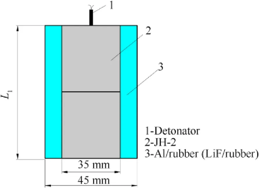
Fig.1. Schematic of the structure of the layered charge.
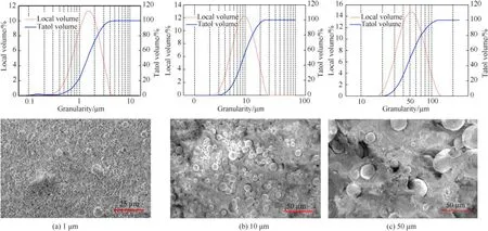
Fig. 2. Granularity analysis results of Al and microstructures of the Al/NR composites with different particle sizes.

Table 1 Typical grain diameters and activities of the Al powders.

Fig. 3. Schematic of the experiments conducted in the 1.3 m3 tank (left) and a photograph of the tank (right).
2.3. Experiments in the 113-m3 bunker
The experiments with relatively large charges were conducted in an explosion bunker with an opening composed of a hemisphere with an inside diameter of 3 m and a cylinder with a height of 2 m as shown in Fig.5.During the test,the layered charge was placed on a support at a height of 1.46 m from the bottom of the bunker.The peak overpressure was measured by four gauges(Y3003,Yangzhou Ryan Electronic Technology Co.,Ltd.,China)with a range of 0.5 MPa set at distances of 1.5(two gauges)and 2 m(two gauges)from the charge.The gauges were fixed by height-adjustable metal brackets and the sensitive surfaces were on the same horizontal plane as the charge center. The images of the explosion process were recorded by a high-speed camera(Fastcam Ultima APX,Photron,Japan)with a sampling frequency of 4301 frames/s and a maximum resolution of 1232 × 900. The detailed experimental schemes are given in Table 2.
3. Results and discussion
The damage of the structural components in a confined space caused by the explosion pressure field mainly includes two stages.The first stage from detonation to the end of product expansion can be regarded as an isentropic process, generating an initial highfrequency explosion wave. Subsequently, the shock wave reflects and converges, and the fuel burns within tens of milliseconds,leading to further collapse of the entire structure. Generally, the peak overpressure is related to the first stage,while the quasi-static pressure and pressure impulse depend on the two stages[20-22].
3.1. Pressure histories in the 1.3-m3 tank
3.1.1. Quasi-static pressure
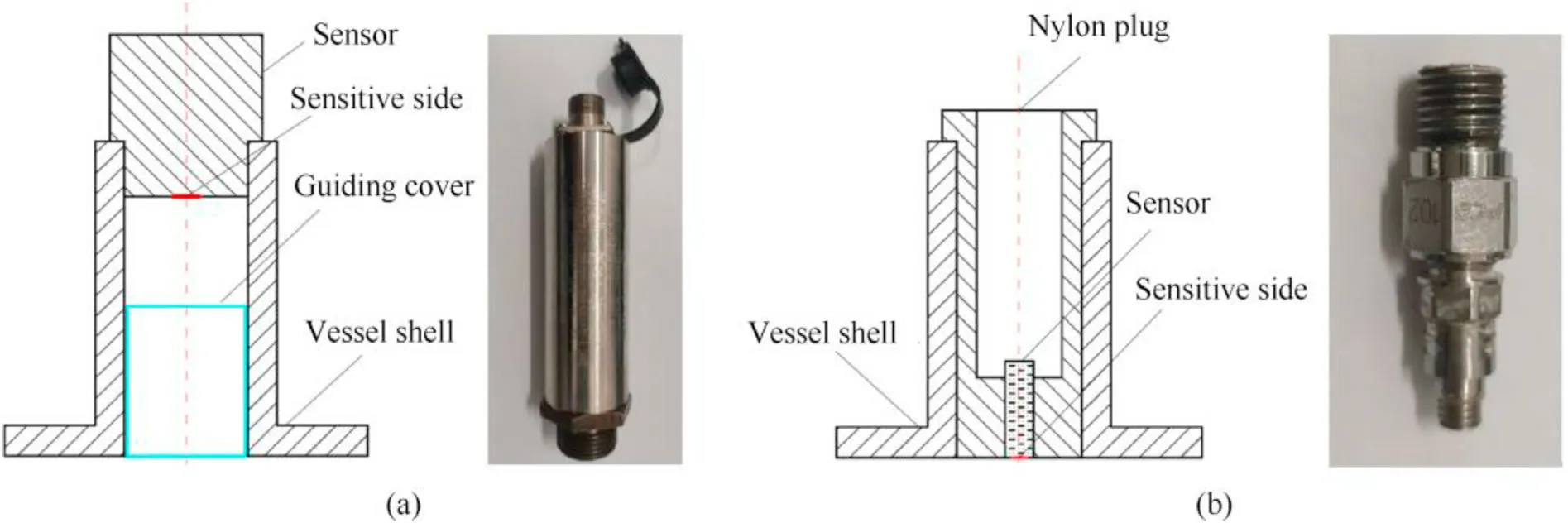
Fig. 4. Schematics of pressure gauge installation and photographs of the pressure gauges: (a) piezoresistive gauge and (b) piezoelectric gauge.
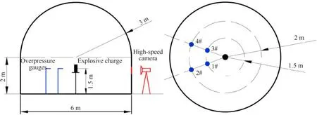
Fig. 5. Schematic of the experiments conducted in the 113-m3 bunker.
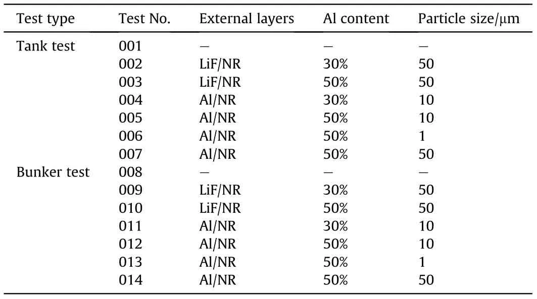
Table 2 Experimental schemes and properties of the envelopes for the tests in the tank and bunker.
The quasi-static pressure-time history curves for test No. 001 and 004 measured in the 1.3 mtank using piezoresistive gauges are shown in Fig. 6. The drastic oscillations in the overpressure within 30 ms were caused by shock wave reverberations on the inner wall of the tank, and their amplitude decreased with time.Owing to the reaction of Al with oxygen from air and the oxidizing intermediates from the detonation products in the initial explosion,the amplitude and rise time of the charge with Al-30%-10 were longer than those of the pure JH-2 charge.Subsequently,the curve slightly decreased and remained within a certain pressure range for a long time(>200 ms),revealing transmission of heat between the gases on both sides of the tank,as well as continuous energy release of the burning Al.The results in Ref.[23]suggested that the quasistatic pressure can be calculated using the average of the pressure over a period of time. Considering that the recorded overpressure histories in the experiments tended to be stable after 30 ms, the Δpwas calculated using the average value between 30 and 50 ms in the test curve.Values of Δpdetermined on the basis of at least two measured histories are given in Table 3.
The Δpvalues measured in the tank (Fig. 7) showed that the use of the Al/NR layer increased the quasi-static pressure by at least 2.14 times compared with the pure JH-2 charge, suggesting that combustion of Al improved the energy release of the charge in the tank.As shown in Fig.7,the difference between the Δpvalues of Al/NR and LiF/NR increased by 23.7% when the particle content increased from 30% to 50%. This was significantly lower than the improvement in the Al loading((50%-30%)/30%=66.7%),revealing the apparent difference in the reaction ratios of Al for the two layers.To quantitatively characterize the contribution of Al from the reactive layer to Δp, the quasi-static pressure was calculated based on the assumption of complete reaction of Al.
Many works concerning the prediction methods for gas pressures for different types of internal explosions including high explosives,high explosives plus combustibles,gas mixtures and dust suspensions have been done in Ref.[24].For explosion of a charge with volume Vin a fully confined space with volume V, the conservation of energy law can be summarized as follows [25]:

Fig. 6. Representative quasi-static pressure histories for test No. 001 and 004 in the 1.3-m3 tank.

Table 3 ΔpQS values determined by the overpressure histories measured in the 1.3-m3 tank and from theoretical calculation.
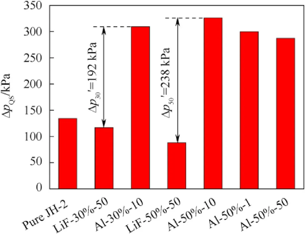
Fig. 7. ΔpQS for charges with LiF/NR and Al/NR layers exploding in the 1.3 m3 tank.


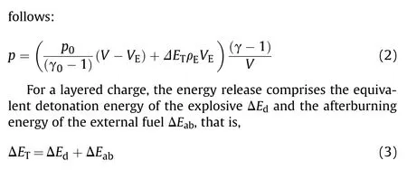
The detailed calculation process of ΔE,ΔE,and γ are provided in Appendix A.The calculated quasi-static pressure Δpand the ratio of the measured and calculated pressures η are given in Table 3.In fact,η represents the combustion efficiency of Al,for the quasi-static pressure difference of charges with different active layers mainly depends on combustion of Al in the afterburning stage. Table 1 presented the ratio of η = 66.4% for Al-50%-10 was lower than that of η=82.2%for Al-30%-10,which is consistent with the abovementioned test results in which the layers with higher Al content showed less improvement in Δp. Generally, the main issue affecting the combustion efficiency of the aluminized envelope around the layered charge is that there must be sufficient energy from the primary detonation to achieve the ignition temperature of Al [26]. For the same weight of the internal explosive,more energy is required to heat the fuels in Al-50%-10,which may result in reduction of the overall reaction temperature and insufficient combustion of Al. It should be noted that Al not only reacts with oxygen from air,but it also reacts with CO,CO,and HO from the detonation products under real conditions, and the adiabatic index also tends to decrease with increasing temperature and increase with increasing pressure [27]. Therefore, the theoretical results may show some deviation from the real values, and accurate values will be calculated in the future.
It can be seen from the values of the measured quasi-static pressures in Fig. 7 that the layers with 10 μm Al presents the highest value of Δp. Compared with the charge with 50 μm Al,Δpfor charges with 1 μm and 10 μm Al were increased by 4.3%and 13.4%, respectively. In fact, combustion of Al in the layered charge mainly includes two stages. The first stage is related to heating and ignition of Al during detonation and expansion of the explosion cloud, while the second stage involves the more complete combustion of Al with oxygen from the air in the tank.On the one hand, larger Al particles may show a lower temperature rise and a lower reaction rate after detonation, leading to a larger amount of Al existing as inert particles in the detonation reaction zone and explosion cloud. In the second stage, the contact area between the larger Al particles and air in the same space is less owing to their smaller total surface area, which also reduces the reaction completeness of Al. On the other hand,the use of smaller Al particles can increase the combustion efficiency and decrease two-phase flow losses to a certain extent[28],but it would reduce the energy release owing to the higher inert AlOcoating content[5]. Hence, the quasi-static pressure generated by the layered charge has no absolute correlation with the Al size,explaining why the moderate 10 μm Al particles showed the best enhancement effect of Δp.
3.1.2. Special pressure impulse
In addition to the quasi-static pressure, the pressure impulse obtained from a specified time duration is another essential blast wave characteristic of a confined explosion. From the typical histories of the overpressure measured in the 1.3 mtank using piezoelectric gauges as presented in Fig. 8, the curve showed the multipeak characteristic, and the peak values for the charges with active layers(test No.004)were clearly higher than that of the pure JH-2 charge(test No.001).In general,the layer will be driven by the gas product and heated to a higher temperature after detonation of the inner explosive.A strong reflected wave will then be generated owing to the interaction between the initial blast wave and the inner wall of the tank, increasing the ambient temperature and mixing of Al and the gas product. In addition, the turbulent flow burning at the wavefront increases [29,30] and the blast wave is further enhanced,leading to multiple peaks at different times.
For an explosion in a confined space,the measured first peak of the overpressure may deviate from the real result because the unreacted agglomerated products will inevitably hit the sensitive surface of the gauge, generating an extra pressure response. In addition, the resonance between the gauges and the tank will interfere with the signal capture. To minimize the experimental error,the special impulse was selected as the test parameters in the 1.3 mtank test,which exhibits an accumulation effect and can be determined by the test results over a period of time as follows:

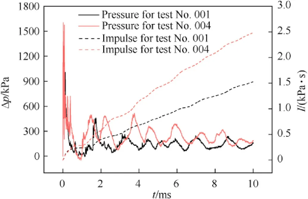
Fig. 8. Representative impulse histories for test No. 001 and 004 measured in the 1.3 m3 tank.
where τ is the special duration. The overpressure histories for a time period of 10 ms after the shock wave reached the gauges were used to determine the impulse owing to the obvious multimodality of the curve.From the histories of the impulses as shown in Fig.9,the final value of the impulse for the charge with Al-50%-10 was the largest, and it was 1.88 times that for the pure JH-2 charge. The increase was less than that in the quasi-static pressure, revealing that accumulation of the energy released gradually increased with time.When the Al content of the layers was increased from 30%to 50%,I increased by 13%,which was much lower than the increase in Al loading owing to the decrease of η. In addition, the impulse for the charge with Al-50%-50 was even lower than that with Al-30%-10,indicating that the particle size is a very important influencing factor for the combustion process of Al.Another significant feature in Fig.9 is that the impulse almost linearly increased,indicating the good air tightness of the tank and stable combustion rate of Al.
3.2. Explosion images and pressure histories in the 113-m3 bunker
3.2.1. Images of the explosion process
Typical images of the growth of the explosion cloud for charges with reactive Al/NR and inert LiF/NR obtained in the 113 mbunker are shown in Fig. 10. To investigate the expansion process, the radius of the fireball was uniformly determined by a ray,which was starts from the initiation point,and 10from the horizontal.For the recorded images,the time of the first observation of light was taken as t=0.The fireball of charge with LiF-50%-50(test No.010)rapidly expanded with a radius of 0.283 m in the first image with light(Fig.10(a)).At t=0.233 ms,the expansion radius reached 0.631 m and the inert agglomerated products were observed. The fireball began to be covered by black smoke and gradually disappeared at around 0.466 ms after detonation, which may be related to unreacted inert LiF/NR dispersal and carbonization of rubber at high temperature[31].From Fig.10(a),the radius increment of the fireball decreased in the same interval(Δt=0.233 ms),which is in agreement with evolution of the fireballs of traditional thermobaric explosives[32,33]. Hence, the radius was fitted by

where Ris the maximum radius and b is a constant related to the growth of the explosion cloud.The fitted result showed that the maximum expansion radius of the fireball was 1.166 m (Fig.11).
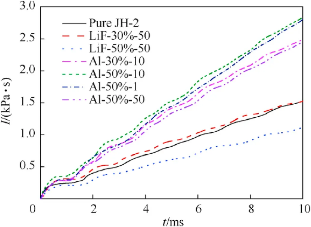
Fig. 9. Special impulses for charges with LiF/NR and Al/NR layers exploding in the 1.3 m3 tank.
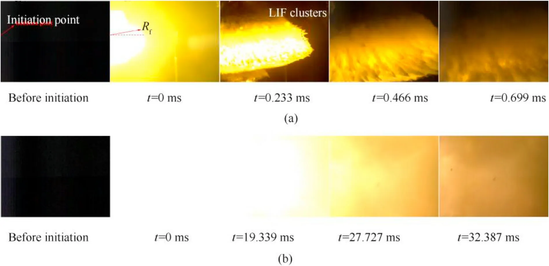
Fig.10. Typical images of the explosion process of charges with inert and active layers obtained in the 113 m3 bunker:(a)LiF-50%-50(test No.010)and(b)Al-50%-10(test No.012).
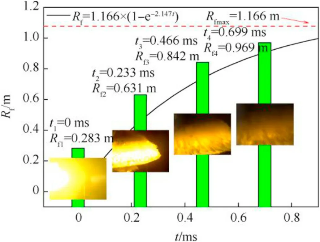
Fig.11. Fitted curve of the expansion radius-time history for test No. 010.
Typical images of the charge with Al-50%-10 are shown in Fig.10(b).Owing to combustion of Al with oxygen from air and the oxidizing intermediates from the detonation products, the highspeed photography rapidly reached light saturation and white light covered the entire field of view until t=19.339 ms.Reflection and convergence of the shockwaves and intense combustion of Al resulted in high-intensity light. Subsequently, the light away from the initiation point weakened and gradually disappeared.The times when the high-intensity light began to weaken for charges with different Al/NR layers are given in Table 4.The high-intensity light durations for different reactive layers were between 15 and 20 ms,reflecting the durations of intense reaction of Al in the 113-mbunker.

Table 4 Durations of high-intensity light for charges with different Al/NR layers obtained in the 113 m3 bunker.
3.2.2. Peak overpressure
To investigate the characteristics of the primary blast waves generated by the layered charges,the overpressures at distances of 1.5 and 2 m from the charge in the 113 mbunker were determined.The overpressure histories suggested that the pressure traces at the same distance were similar(Fig.12(a)).Notably,the reflected shock waves in the relatively large bunker were not as strong as the overpressure results in the relatively small tank owing to the longer distance between the charge and the wall. To accurately determined the peak overpressure of the primary blast waves, the history curves were fitted by Ref. [34].

where p is the instant overpressure, pis the peak overpressure behind the primary shock wave,α is a coefficient,t is the time after arrival of the primary shock wave, and tis the positive duration.The fitted curves obtained using the least square method are shown in Fig.12(b). Compared with the results at a distance of 1.5 m, the peak overpressure decreased and the positive duration increased at 2 m,revealing attenuation and dissipation of the shock wave in air.
The Δpvalues of the layered charges in the bunker are shown in Fig. 13. It can be assumed that the peak overpressure of the charges with LiF-30%-50 and LiF-50%-50 were less than that of the pure JH-2 charge. On the one hand, the energy release from combustion of rubber in inert LiF/NR hardly enhanced the strength of the primary blast wave. On the other hand, the strength effect of LiF/NR cannot be ignored, because elastic deformation of the rubber molecular chains and destruction of the LiF powder may absorb the initial blast energy and decrease the amplitude of the shock wave. This conclusion is also supported by the charge with larger inert loading (LiF-50%-50) showing lower peak overpressure.
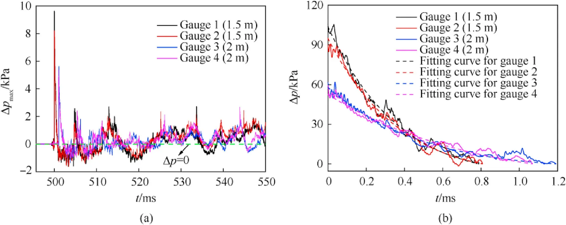
Fig.12. Representative overpressure histories for test No. 008 in the 113 m3 bunker: (a) measured curves and (b) fitted curves.
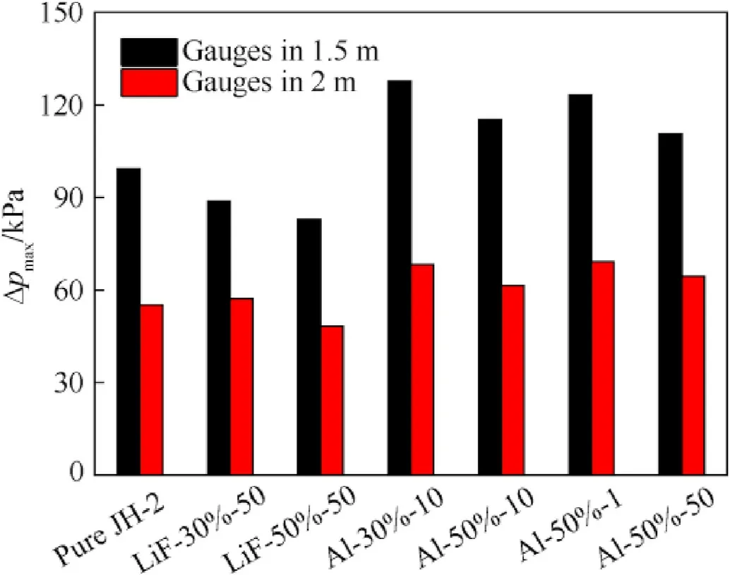
Fig.13. Δpmax for charges with LiF/NR and Al/NR layers exploding in the bunker.
The measured Δpvalues in Fig.13 confirmed that burning of Al during explosive detonation and expansion of the explosion cloud improved the peak overpressure.The charge with Al-30%-10 generated the largest peak overpressure of 127.71 kPa at a distance of 2 m, which was 28% higher than that of the pure JH-2 charge.Differing from the test results in the tank, the peak overpressure decreased when the Al loading in the layer was increased from 30%to 50%.In fact,the intensity of peak overpressures for charges with Al/NR layers suggested that the enhancement caused by Al combustion was greater than the weakening effect caused by energy absorption of the layers. For Al-50%-10, the energy absorption capability significantly increased owing to higher wave impedance,while the increase of the energy release was not obvious,resulting in higher peak overpressure for the charge with Al-30%-10. The Δpresults in Fig.13 also showed that the charge with Al-50%-1 generated better blast performance than those with Al-50%-10 and Al-50%-50, indicating higher combustion rate and energy releasefor the 1 μm Al particles.The values of the fitted peak overpressure are given in Table 5.

Table 5 Δpmax values determined by the overpressure histories measured in the bunker.
4. Conclusion
We have investigated the blast performance of layered charges with aluminum powder/rubber composite envelopes. The explosion experiments were conducted in confined spaces of 1.3 and 113 m, and the blast parameters and images of the explosion process were recorded. The following conclusions were drawn:
(1) The use of an Al/NR layer increased the quasi-static pressure,special impulse, and peak overpressure by up to 143%, 88%and 29%,respectively,owing to combustion of Al both in the first stage from detonation to the end of product expansion and the subsequent stage involving reflection of the shock waves and interaction between the fuels and the wall.
(2) When the Al content was increased from 30% to 50%, the improvements of Δpand I were clearly less than the increase of the Al loading amount because of the decreased combustion efficiency of Al, while Δpeven decreased by 9.7% owing to greater absorption of the blast wave energy.
(3) The charge with 1 μm Al particle layer produced higher Δpcompared with the 10 and 50 μm Al particle layers owing to the higher reaction rate of the smaller Al particles during generation of the primary blast wave.The Δpand I values for the charge with 10 μm Al particles were the largest, meaning that the 10 μm Al particles burned more thoroughly and released more energy in a longer period(up to 50 ms).
(4) Growth of the fireball with a maximum expansion radius of 1.166 m and the inert agglomerated products were observed for charge with inert LiF-50%-50 within 1 ms.For the charges enveloped by Al/NR layers, the intense combustion of Al produced high-intensity light lasting for 15-20 ms in the confined bunker.
We declare that we have no known competing financial interests or personal relationships that could have appeared to influence the work reported in this paper.
The work presented in this paper has been funded by the National Natural Science Foundation of China (Grant No. 11972018)and the Defense Pre-Research Joint Foundation of Chinese Ordnance Industry (Grant No.6141B012858).
Appendix A. Determination of equivalent detonation energy ΔE, afterburning energy ΔE, and adiabatic index γ
(a) Equivalent detonation energy
The velocity of out layer vcan be firstly calculated using Eq.(7)as follows [35]:
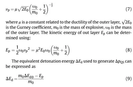
where ΔEis the detonation energy of JH-2. Specific values of parameters of JH-2 and outer layer are given in Table 6 [36,37].
(b) Afterburning energy
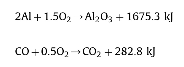
Calculating results showed that the Ocontent, the maximum content of Al and the combustible gas from the detonation products(refers to CO in this article) are 12.19 mol,1.19 mol and 0.89 mol[27], respectively, therefore the oxygen in the test can be considered sufficient to support the complete combustion of Al and detonation products, and the afterburning energy ΔEcan be determined by the chemical reaction as follows [38]:
(c) Adiabatic index of the air-charge gas mixture
For the determination of the adiabatic index of the gas mixture γ, it can be determined by averaging the adiabatic indexes of the gases:

where n(i)is the number of moles of each gas,nis the total number of moles of the gas mixture,γ(i)is the adiabatic index of each gas,which generally decreases with increasing temperature and increases with increasing pressure, as shown in Fig.14 [39].
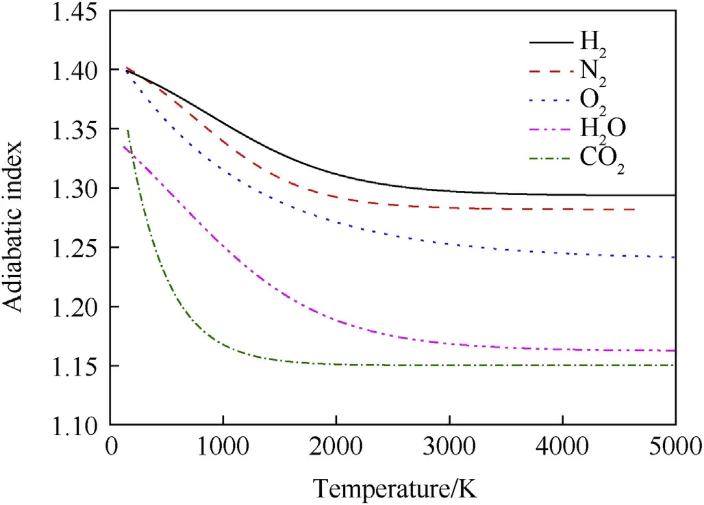
Fig. 14. Relationships between the adiabatic indexes and temperature for different gases [39].

Table 6 Values of parameters of JH-2 and outer layer.
The composition of gas mixture can be determined by Brinkley-Wilson rule [27], while the temperature of the gas mixture can be calculated according to Ref. [25], where a thermodynamic equation was expressed as follows:

where ΔQ is the total heat released from the chemical reaction(J),nis the total number of moles of the gas mixture, Tis the initial temperature(298 K),Tis the temperature(K),and Cis the heat capacity of the gas mixture at constant pressure (J·molK). In general,Ccan be determined by averaging the heat capacities of the gases as follows:

where C(i) is the heat capacity of each gas [25].
杂志排行
Defence Technology的其它文章
- Research on DSO vision positioning technology based on binocular stereo panoramic vision system
- Dynamics of luffing motion of a hydraulically driven shell manipulator with revolute clearance joints
- Chemical design and characterization of cellulosic derivatives containing high-nitrogen functional groups: Towards the next generation of energetic biopolymers
- Applicability of unique scarf joint configuration in friction stir welding of AA6061-T6: Analysis of torque, force, microstructure and mechanical properties
- Multi-area detection sensitivity calculation model and detection blind areas influence analysis of photoelectric detection target
- Accurate analysis of limiting human dose of non-lethal laser weapons
