Multi-area detection sensitivity calculation model and detection blind areas influence analysis of photoelectric detection target
2022-04-19HanshanLiXiaoqianZhangHuiGuan
Han-shan Li, Xiao-qian Zhang, Hui Guan
School of Electronic and Information Engineering, Xi’an Technological University, Xi’an, 710021, China
Keywords:Projectile Photoelectric detection target Multi-element array photoelectric detector Detection sensitivity Detection screen
ABSTRACT Multi-element array photoelectric detector is the core devices to form a photoelectric detection target with a large field of view. This photoelectric detection target brings about the problem of uneven detection sensitivity distribution in the detection screen. To improve the uneven detection sensitivity of this photoelectric detection target, this paper analyzes the distribution law of the uneven detection sensitivity of the photoelectric detection target using the multi-element array photoelectric detector,dissects the main factors affecting the detection sensitivity according to the photoelectric detection principle, establishes the calculation model of detection sensitivity of the photoelectric detection target in the different detection areas and proposes a method to improve the detection sensitivity by compensating the gain of each unit photoelectric detector. The analysis of simulation and experimental results show that the proposed method of photoelectric detection target can effectively improve the output signal amplitude of the projectile under the certain detection distance, in particular, the output signal amplitude of the projectile is significantly increased when the projectile passes through the detection blind area. The experimental results are consistent with the simulation results, which verify the effectiveness of the proposed improvement method.
1. Introduction
In the field of weapon testing,photoelectric detection target is a photoelectric detection sensor, which is composed of an optical system, slit diaphragm, photoelectric detector, and signal processing circuit,it is mainly used to detect flying projectile information.According to the structural characteristics of the photoelectric detection target,its field of view formed based on the action of the slit diaphragm is a fan-shaped detection screen with a certain thickness [1]. In the test of shooting range, we use multiple photoelectric detection targets to form multi-screen intersection model, and measure the velocity and coordinates of flying projectile [2-5]. Reference [6] present a method for testing the burst point position of projectiles by using a combination of four-screen intersection and flash detectors,and give the calculation function of the burst point coordinates. Authors in Ref. [7] study a coordinate measurement of six-light-screen array sky screen vertical target based on engineering model. In Ref. [8], Authors present a technique by changing the sensitivity of large target area detection for indoor environment. These test methods are based on a system formed on the highly sensitive photoelectric detection targets, the performance of the photoelectric detection target determines the reliability of the testing system.
The conventional photoelectric detection target commonly adopts a unit element sensor as the photoelectric detector [9,10].Although the conventional photoelectric detection target has relatively strong detection capability, the area of the unit element sensor is small, causing the conventional photoelectric detection target to have a small detection field of view. Therefore, the conventional photoelectric detection target can’t meet the test requirements of new weapon launch projectile with uncertain dispersion state. In order to improve the shortcomings of the conventional photoelectric detection target, the multi-element array photoelectric detector has the characteristics of low noise,fast response and high detection sensitivity, and was introduced into the design of the photoelectric detection target; considering the detection sensitivity and the detection field of view, the photoelectric detection target has a consistent and high response speed and meets the test requirements of large field of view. However,there is a small interval between the multi-element array photoelectric detector, namely, the entire detection screen has many small detection blind areas.When the projectile passes through the detection blind area and the detection distance is higher, the detection blind area is unable to detect the flight target. Thus, the photoelectric detection target using the multi-element array photoelectric detector has obvious deficiencies,and which is an uneven distribution of detection sensitivity of this test equipment.Based on the detection principle of the photoelectric detection target, the optical characteristics of the flight projectile considering the thickness of the detection screen is studied and established the calculation model of the minimum luminous flux of the photoelectric detection target to improve the detection sensitivity [11].The relationship of the detection sensitivity and the area light source is studied, and then established the relation model of the detection sensitivity,the radius of the light source and the length of the focal plane array reflection surface, and obtained the design criterion of the size of the light source and the length of the mirror[12]; The calculation model of detection sensitivity of the large detection area is constructed and provided the correction method of detection[13].This test system adopted the unit detector or the artificial light source, the method or the calculation model have some contributions to improve the detection sensitivity of the photoelectric detection target. For multi-element array photoelectric detector as the core of the photoelectric detection target, the defocus dispersion method to improve the effect of the detection blind area is proposed, but the detection capability of this photoelectric detection target is reduced.
In order to improve the detection performance of photoelectric detection target with large field of view, this paper establishes a regional detection sensitivity calculation model and adjusts the gain of the signal processing circuit of the unit photoelectric detector to improve the detection sensitivity of the entire detection area. The work in this paper provides a theoretical basis for the design of the photoelectric detection system with stable detection performance under a certain detection distance.
2. Detection sensitivity model of photoelectric detection target
2.1. Deficiency and analysis of traditional photoelectric detection target
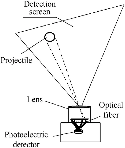
Fig.1. Schematic diagram of traditional photoelectric detection target.
The traditional photoelectric detection target uses a single panel photoelectric detection receiver to capture the flight projectile information, as shown in Fig. 1. This structural principle and method mainly adopts the optical fiber convergence method[14-16], that is, the signal of projectile’s luminous flux change in the detection screen is gathered to the photosensitive surface of a single photoelectric detection receiver, and the recognizable projectile signal can be formed through the amplification processing of the amplification circuit.Due to the small photosensitive surface of the photoelectric detection receiver,the amplification circuit is less affected by the external environment light, and the gain of the detection circuit can be greatly improved, however, there are two shortcomings in this design method of the traditional photoelectric detection target.One is that the structure system is collected by slit diaphragm and optical fiber. In the arrangement and combination of optical fibers, the optical fiber will lose a certain amount of energy, which makes the detection capability of the whole photoelectric detection target low. On the other hand, due to the limitation of the photosensitive surface of the photoelectric detection receiver,even if the number of optical fibers is increased,the effective information of projectile luminous flux can be formed at the convergence port,but,the information of projectile luminous flux is translated into the energy on the photosensitive surface of the photoelectric detection receiver also limited, so the detection field of view is not increased [17].
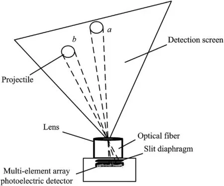
Fig. 2. Schematic diagram of new photoelectric detection target.
In view of the shortcomings of this design method, this paper proposes to use the multi-element array photoelectric detector with high flexibility and low noise as the detection measure of photoelectric detection target and apply the defocus optical imaging technology to design the detection light path system. The traditional complex structure of optical fiber convergence reception is transformed into the optical lens directly converging to the photosensitive surface of the array photoelectric detector through the slit aperture,as shown in Fig.2,the array photoelectric detector is placed the position that the multi-element array photoelectric detector is at a distance from the imaging focal plane. We have introduced defocus optical imaging technology to obtain the same projectile imaging spot at the same detection distance in any field of view, which make the loss of the imaging spot on the photosensitive surface of multi-element array photoelectric detector is basically the same, it can eliminate the problem of the detection blind area in the two-unit detection blind area.This design method improves the efficiency of directly obtaining projectile information in the detection screen, and greatly improves the detection sensitivity.From the principle of Fig.2,it is not difficult to find that this method improves the detection capability of the traditional photoelectric detection target. However, the photoelectric detection receiver adopts the splicing technology, so there is a blind area between the two small unit photoelectric detectors. From the optical imaging principle, the detection distance increases, and the probability of the projectile passing through the detection blind area increases. In Fig. 2, the detection distance of position b is shorter than that of position a.When the projectile passes through the detection screen at the position b, because of the short detection distance, the projectile imaging spot is relatively large. When the projectile imaging spot falls between the two unit photoelectric detector,the ratio of the lost energy of the detection blind area and the energy of the whole projectile imaging spot is relatively small,so the detection blind area has little effect on the detection capability of the whole photoelectric detection target,but the projectile passes through the detection screen at the position a,the projectile imaging spot is relatively small, and the ratio of the lost energy of the detection blind area and the energy of the whole photoelectric detection target becomes bigger, which makes the photoelectric detection target may not recognize the projectile signal,resulting in the low capture rate. Based on the detection mechanism of array photoelectric detection receiver, the imaging area of each unit photoelectric detector is corresponding to the detection screen to form multiple detection area,which can find that there is a certain blind area in the detection screen.In order to scientifically analyze and improve the optimization design of photoelectric detection target, this paper establishes the calculation model of multi-area detection sensitivity of photoelectric detection target, and proposes adaptive gain method for adjacent photoelectric detectors based on this model.
2.2. Multi-area detection sensitivity calculation model of new photoelectric detection target
In the photoelectric detection target, the luminous flux of the photoelectric detector is changed when the projectile passes through the detection screen,and the received luminous flux of the photoelectric detector from the target and the background directly affects the detection sensitivity. Therefore, to study the detection sensitivity of photoelectric detection target, it is necessary to establish the calculation model of the changed luminous flux of photoelectric detector caused by the flight target and the background in the detection area.
The detection screen of the conventional photoelectric detection target has small detection field of view.Since the detection field of view of the conventional photoelectric detection target is small,the edge effect of the optical lens can be ignored. When the projectile passes through the detection screen, the luminous flux of the photoelectric detector is affected by the background brightness,the size of the projectile, the detection distance and the relationship between the length of projectile and the thickness of the detection screen[18,19].Thus,the received luminous flux of the photoelectric detector can be expressed as:

In Eq.(1),H is the detection distance,f is the focal length of the optical lens, d and l are the diameter and the length of the projectile, respectively, b is the width of slit diaphragm, τ is the transmission coefficient of optical lens, E is the background brightness, and K is the thickness of the detection screen [20].
For the photoelectric detection target using the multi-element array photoelectric detector, the detection screen has large detection field of view and has a small detection blind area between the unit photoelectric detectors, the rectangular slit diaphragm is located in the focal plane. Thus, there are many small detection blind areas. The schematic diagram of the detection light path of the photoelectric detection target is shown in Fig.3.
In Fig.3,the whole area of the detection screen is divided into 2n small areas. The widths of 2n small areas are the same, meaning that the angle (denoted as ω) between the i-th unit area and the center of the optical axis is different. Multi-element array photoelectric detectors are put together to form the larger detection field of view,and also have many detection blind areas in the detection screen.When no projectile passes through the detection screen,in order to establish the calculation model of the luminous flux of multi-element array photoelectric detectors, the following factors should be considered:background brightness,the transmittance of optical lens, the width of the detection blind area, and the transmission coefficient of optical lens, especially, the detection blind area. This paper establishes the calculation function of luminous flux on the multi-element array photoelectric detector as:

In Eq. (2), ais the width of the unit photoelectric detector, εand ε are the optimal and the actual defocus amounts,respectively,ξ is the luminous flux attenuation coefficient caused by the defocus dispersion method, 2n is the number of small areas of whole detection screen and Γ(x)is the radiant illumination on the surface of the photoelectric detector at a different field of view and same detection distance.
When the projectile passes through the detection screen at the same detection distance, the radiant illumination is different at a different field of view mainly because of the effect of the detection blind area. Thus, the radiant illumination is represented as:

In Eq. (3), ais the length of the multi-element array photoelectric detector, ais the width of the detection blind area, and a= 2na+ (2n - 1)a.
When the projectile passes through the detection screen,there is a high probability that it is located in the detection blind area.Once the projectile passes through the detection blind area, the received luminous flux of the photoelectric detector is very small,which causes the detection sensitivity to drop dramatically. If the detection distance increases, the width of the detection blind area increases and its influence becomes more obvious.When the width of the detection blind area is greater than the diameter of the target,the target cannot be detected, resulting in a missed measurement of the system. By using the defocusing dispersion method, the imaging area of the target on the photoelectric detector can be increased and the influence of the detection blind area can be reduced in a certain range of detection distance. However, as the detection distance increases, the width of the detection blind area also increases, causing an increase in the missed measurements and making the detection performance of this photoelectric detection target unstable. Based on the calculation model of the luminous flux of the traditional photoelectric detection target and considering the detection blind area, the calculation model of the received luminous flux of photoelectric detector for photoelectric detection target with larger detection field is established as:

In Eq. (4), D is the aperture of the optical lens. It can be found from Eq.(4)that the length of the projectile and the thickness of the detection screen are different. Hence, the calculation model of the received luminous flux of the photoelectric detector is also different.
To analyze the detection performance of the photoelectric detection target using the multi-element array photoelectric detector,the calculation model of the detection sensitivity need to be set up. According to the detection principle of the photoelectric detection target,the detection sensitivity depends on the changed luminous flux of the photoelectric detector [21-23]. Under the same test conditions, when the projectile passes through the detection screen, the received luminous flux of the photoelectric detector is large at the same detection distance, namely, the detection sensitivity is high.Otherwise,the detection sensitivity is low.Therefore,the calculation model of the detection sensitivity is given as follows:
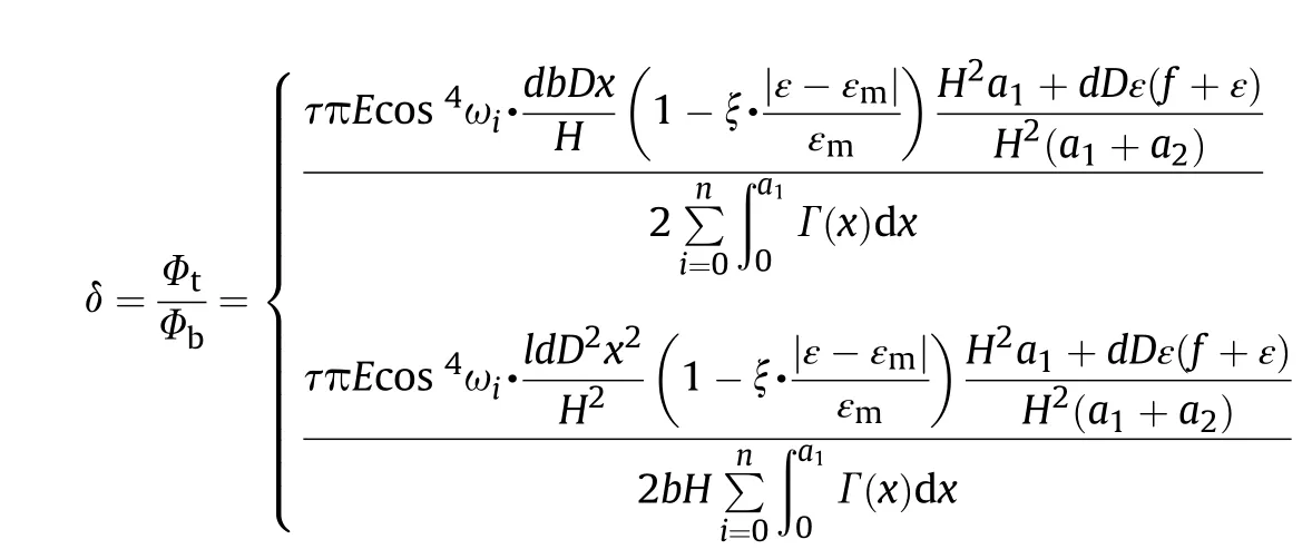
According to the photoelectric conversion theory of the photoelectric detection target, assuming that Ais the magnification of the signal processing circuit,ρis the sensitivity of the photoelectric detector andR is the equivalent resistance of the detection circuit,the received luminous flux of the photoelectric detector is converted into the voltage signal [24], which is expressed as:
In Eq. (6), Nis the number of signal electrons of photoelectric detection receiver caused by the projectile in the detection screen,t is the time that projectile pass through the detection screen.
2.3. Detection blind area analysis and adaptive method
From the design method and principle of photoelectric detection target,we propose to use a multi-element array photoelectric detector with high-sensitivity and low-noise as the core detection unit. The main consideration is to maintain the flexibility of the existing photoelectric detection target, and also consider the characteristic of optical lens with short-focus and large-view.Based on the optical lens with short-focus and large-view, the paper combines the imaging characteristics of the multi-element array photoelectric detector and establish a multi-area detection sensitivity model. From the perspective of improving the detection sensitivity of each area and making the detection ability of the entire detection screen consistent, this measure does play a very good role.
Eq.(6)gives the output signal calculation function of the system based on the relationship between the length of projectile and the thickness of detection screen.For the photoelectric detection target with the array photoelectric detector as the core, whether the length of projectile is greater than or less than the thickness of detection screen, there is a detection blind area between the two
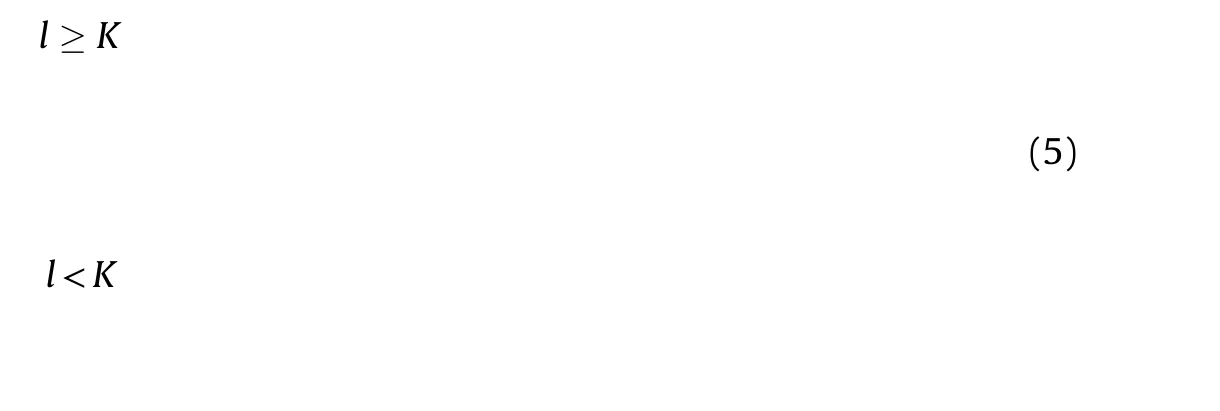
unit photoelectric detector. We introduce the imaging spot calculation method,and set up the signal to noise ratio of the system by using the ratio of the projectile imaging spot and the blind area,give the calculation function of signal electrons number in the detection screen.
According to the calculation function of optical imaging spot[25], the area of imaging spot is expressed as:

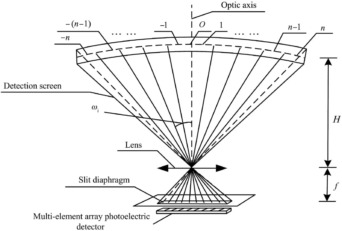
Fig. 3. Schematic diagram of the detection light path of the photoelectric detection target.
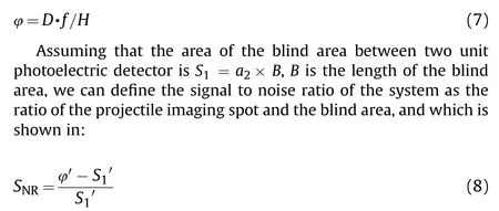
In Eq. (8), Sis the area of projectile imaging spot on the detection blind area, φis the effective imaging spot on the photoelectric detector.When φ =φ>B,and the center of the projectile imaging spot is consistent with the center of the blind area,namely,S= S, the loss energy is the largest. According to Eq. (7), as the detection distance increase, the imaging spot decreases, and the signal to noise ratio decreases. If φ >>S, Sis the photosensitive area of the unit photoelectric detector, and which is determined according to the light flux generated by the projectile in the detection screen and the number of signal electrons received by the photoelectric detector [26]. If the quantum efficiency of the unit photoelectric detector is η, the number of signal electrons of the photoelectric detector caused by the projectile in the detection screen is:

In Eq. (9), Sis the lost energy of projectile imaging spot at the detection distance of H,Sis equal to the sum of the blind area of the photoelectric detector and the area of the projectile imaging spot falling outside the photosensitive surface of the photoelectric detector,h is the Boltzmann coefficient,c is the speed of light,λ is the spectral wavelength, and v is the velocity of flight projectile [27].Therefore, the output signal of equation (6) is determined byN,there is the corresponding gain circuit in the detection circuit for each photoelectric detector,in Eq.(6),Arepresents the total gain of array photoelectric detector, and A∈(A,A,…,A), the design structure of the detection circuit is shown in Fig.4,dis the i-th unit photoelectric detector, the gain of detection circuit 2n is A. After detection by each unit photoelectric detector, the signal is superimposed as the final output, the detection output of each unit photoelectric detector has an independent signal acquisition and judgment module, this module is a prerequisite for adaptive gain adjustment [28]. The basic principle is to use the output signal amplitude captured by the previous projectile,and change the gain and noise processing coefficient of the unit photoelectric detection circuit according to the adjustment criteria, satisfy the acquisition and recognition of the next projectile in the same region of detection screen, achieve the photoelectric detection target effective detect when the output signal does not meet the recognition minimum signal to noise ratio.
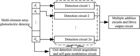
Fig. 4. The design structure of the detection circuit.
In order to fully analyze the influence of the detection blind area,according to the data many tests, we set up the judgment criteria,first, the detection circuit gain is divided into three levels, second,we denote the output basic signal of unit photoelectric detector as V(i =1,2,…,2n),Vas the average noise of the unit photoelectric detector,when V∈(1.0V,2.5V),it is considered that the output signal caused by projectile imaging spot is relatively weak,from the average noise of the unit photoelectric detector,and the maximum signal to noise ratio is only 2.5, for photoelectric detection target,the signal-to-noise ratio reaches more than 3.5, the detection performance and recognition rate of photoelectric detection target is relatively ideal. Therefore, the gain compensation function is established according to the detection law, the formed gain is adjusted based on Eq. (10).

From the point of view of limiting detection distance, the adaptive gain method can make up for the missing detection probability caused by the uneven detection sensitivity of the photoelectric detection target with the array photoelectric detection receiver as the core at a certain distance. Through the new photoelectric detection target designed based on multi-element array photoelectric detector, combined with the relationship between the image spot of projectile and the blind area of the photoelectric detector, the adaptive gain adjustment mode of the actual photoelectric detection target is established,and the performance of the new photoelectric detection target is effectively improved.
3. Simulation and experimental analyses
3.1. Simulation analysis
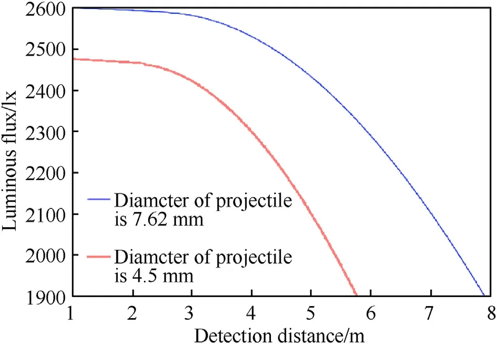
Fig. 5. The relation of the luminous flux of projectile and detection distance under different diameter of projectile.
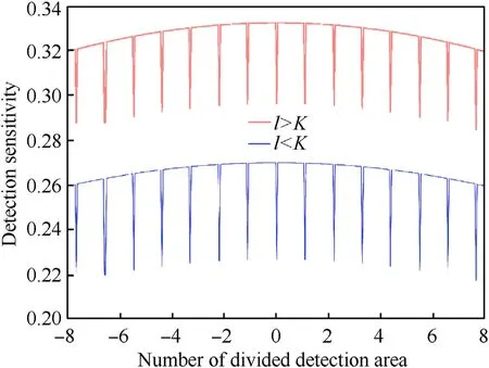
Fig. 6. The distribution curve of detection sensitivity at different detection areas.
For simulations,a multi-element array photoelectric detector is used in the photoelectric detection target that has 16 unit photoelectric detectors, the width of each unit photoelectric detector is about 2.4 mm,the width of the effective photosensitive is 38.4 mm,the detection blind area of the two small units was 0.12 mm, and the actual photosensitive surface length of multi-element array photoelectric detector is 40.2 mm; the responsiveness of multielement array photoelectric detector is 10s, we select a 50 m m focal length lens,the detection field of view can reach 43.8.For projectile’s detection of low extension ballistic in weapon system,the limit detection distance of photoelectric detection target is about 900 times the diameter of projectile that gun shot, this is a general expression to measure the detection ability of a photoelectric detection target. We use the diameter of projectile is 4.5 mm and 7.62 mm to calculation their the limit detection distance, the limit detection distance is 4.05 m and 6.85 m respectively, explore the changes relation between the luminous flux of projectile and the detection distance under different projectile diameters.According to Eq.(4),the change curve of the luminous flux of projectile on multi-element array photoelectric detector is shown in Fig. 5. Fig. 5 describes the relation of the projectile itself luminous flux and detection distance under different diameter of projectile,the shorter the distance,the more obvious the projectile itself image brightness, but also reflects the strong the contrast of projectile imaging spot, the higher the detection sensitivity. The brightness of the projectile itself reflects the luminous flux change of the projectile in the detection screen.
It can be observed from the change curve in Fig.5,that when the detection distance is same, the luminous flux on multi-element array photoelectric detector increases with the increase in the diameter of projectile. However, when the detection distance is large, the luminous flux on the multi-element array photoelectric detector is small.The main reason is that the farther the detection distance, the smaller the target imaging on the photoelectric detector.When the detection distance increases to a certain distance,the length of projectile becomes greater than the thickness of the detection screen and the impact of the detection blind area becomes more obvious.Thus,the attenuation of the luminous flux on the multi-element array photoelectric detector is significant.
The photoelectric detection target using the multi-element array photoelectric detector has the detection blind area, the detection sensitivity of this photoelectric detection target at the entire detection area is different. According to Eq. (5), the distribution curve of detection sensitivity is calculated and shown in Fig. 6.
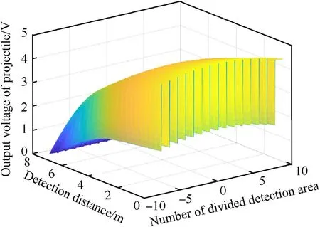
Fig. 7. The change of output voltage of projectile in the whole detection area under different detection distances.
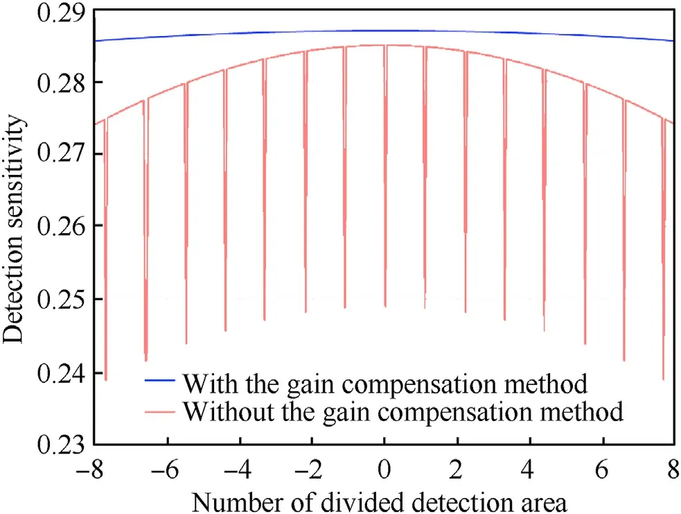
Fig. 8. The distribution curve of detection sensitivity at the detection field of view using the gain compensation method.
In Fig. 6, -1 and 1 represent the central field of view of the detection screen, -2 to - 8 represent the left field of view of the detection screen, and -8 represents the left edge field of view of the detection screen. Similarly, 2 to 8 represent the right field of view of the detection screen,and 8 represents the right edge field of view of the detection screen.At the same detection distance,when the projectile passes the central region of the detection field of view,the detection sensitivity is the highest.The detection field of view changes and deviates from the central field of view. The detection sensitivity is gradually decreased, because the projectile deviates farther from the central field of view,the distance between the projectile and the center point of the optical lens is farther,and the distortion effect of the optical lens is also obvious.Meantime,if the length of projectile is smaller than the thickness of the detection screen, the photosensitive surface of the multi-element array photoelectric detectors is not fully used,making the luminous flux on multi-element array photoelectric detector relatively few, thus the detection sensitivity is lower.If the length of projectile is equal to the thickness of the detection screen,the photosensitive surface of multi-element array photoelectric detectors plays the most important role, so the detection sensitivity is slightly higher. Once the projectile passes through the detection blind area,the effective luminous flux on the array photoelectric detector is less and the attenuation of the detection sensitivity is sharp.Furthermore,with the increase of detection distance,the width of the detection blind area is expanded and the imaging spot of the target acting on the surface of the photoelectric detector becomes smaller.These factors make the impact of the detection blind area on the projectile passing through the detection area more obvious and reduce the amplitude of the output signal of the system.According to Eq. (6),the voltage signals of the entire detection area under different detection distances is shown in Fig. 7.
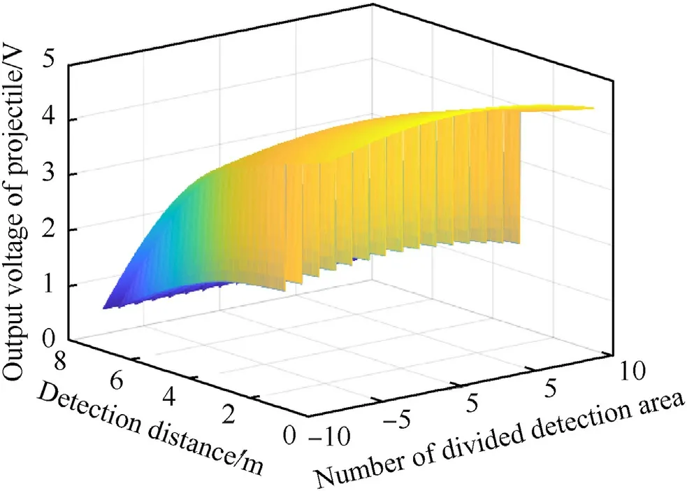
Fig.9. The change of output voltage of projectile of each detection area under different detection distances using the gain compensation method.
The detection sensitivity of this photoelectric detection target is not only related to the sensitivity of the photoelectric detector,but also to the gain of the signal processing circuit. Based on the existing photoelectric detector, this paper proposes the adaptive gain method that is applied to the signal processing circuit of the single-element photoelectric detector.Combining Eqs.(5)and(10),Fig. 8 shows the distribution curve of detection sensitivity at the detection field of view by using the gain compensation method.
In this paper, the gain compensation method is used in the signal processing circuit of the single-element photoelectric detector. It can be seen from the distribution curve of detection sensitivity in Fig. 8 that the detection sensitivity with the gain compensation method in the entire detection area has grown compared with the detection sensitivity without the gain compensation method at a certain detection distance. Due to the gain compensation of the signal processing circuit of the singleelement photoelectric detector, when the projectile passes through the detection blind area, the detection sensitivity at the detection blind area has a significant increase, making the detection sensitivity at the entire detection field of view more consistent.
When the projectile flies over the detection area at a certain detection distance, the width of the detection blind area becomes larger due to the increase of the detection distance.At this time,if the diameter of projectile is smaller than the width of the detection blind area, the blind area will be large in the area of projectile imaging spot and the luminous flux of the photoelectric detectors will reduce. Even if the gain compensation method is used, the system cannot effectively compensate for the missing measurement at the detection blind area. The voltage signals of each detection area under different detection distances using the gain compensation method are shown in Fig. 9.
It can be seen from Fig. 9 that the gain compensation method can effectively compensate for the influence of the detection blind area but is unable to completely eliminate the influence of the detection blind area. Experiments are conducted to further verify the feasibility and effectiveness of the proposed method.
3.2. Experimental analysis
The related parameters of photoelectric detection target have been described in the previous section.Based on the test platform of the photoelectric detection target, the optical lens uses 50 mm,the aperture is 1.4,and the width and length of the slit diaphragm is about 0.3 mm and 42 mm respectively.During the experiment,the target has two different sizes of projectiles, which are air gun and rifle with diameters of 4.5 mm and 7.62 mm, respectively. The wooden target is fixed and is about 10 m away from the photoelectric detection target. The central area of the wooden target is consistent with the central area of the detection screen of the photoelectric detection target.Due to the high-flying velocity of the projectile and the short distance between the photoelectric detection target and the wooden target,the projectile is considered to fly in a straight line.Through the coordinate data that projectile shot on the wooden target, it is verified that the projectile passes through the region of the detecting screen.
Since the width of each unit photoelectric detector is the same,the width of the divided unit detection area is the same at the same detection distance. The angle between the middle detection area and the optical axis center of the optical lens is the biggest and is about 2.9. The angle between the edge detection area and the optical axis center of the optical lens is the smallest, and is about 2.5. Based on the existing conditions of the test device, when the diameter of the projectile is about 4.5 mm, the ideal limiting detection distance of the system is about 4.05 m. At this time, the left edge detection area of the detection screen is about 1.636 m away from the optical axis center of the optical lens, the width of each unit detection area is about 0.198 m,and the width of the blind areas between the unit detection areas is about 8 mm. Since the detection screen is based on the optical axis symmetry of the optical lens, the right side of the detection screen is the same as the arrangement on the left side of the detection screen. When the diameter of the projectile is 7.62 mm, the ideal limiting detection distance of the system is about 6.85 m. At this time, the edge detection area of the detection screen is about 2.767 m away from the optical axis center of the optical lens, the width of each detection area is about 0.334 m, and the width of the blind area between the unit detection areas is about 14 mm.
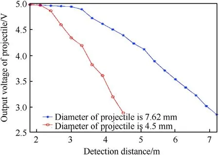
Fig. 10. The change curve of output voltage of projectile under different projectile’s diameters and detection distances.
Tests are conducted to verify the influence of the detection distance on the detection sensitivity of the photoelectric detection target.In the first round of the tests,the shooting position is located in the central area of the detection screen,and the air gun and the rifle are used to shoot at different detection distances. The detection distance starts from 1.8 m, with 0.3 m as the adjustment amount until the detection distance is 7.2 m.Considering the height of the test derive, the shooting height needs to be increased by 0.4 m,when the projectile passes through the detection screen.The recorded output signal of the system is shown in Fig.10.
It can be seen from Fig. 10 that the amplitude of the output signal of the system is affected by the detection distance. The amplitude of the output signal of the system decreases with the increase in the detection distance.At the same time,the diameter of the projectile is large and the detection distance of the system is high, that is, the limiting detection distance of the system is large.The main reason is that when the detection distance is same, the diameter of the projectile is large and the area of the imaging spot on the sensitive surface of the photoelectric detector is the larger,making the luminous flux of the photoelectric detector greater. If the luminous flux of the photoelectric detector is much larger than that of the background radiated to the photoelectric detector, the amplitude of the output signal of the system is also larger,and the projectile passes through the detection screen can be captured. In this test state,the detection sensitivity is relatively high according to the detection sensitivity calculation model of the system.When the diameter of the projectile is fixed,the imaging spot area of the projectile on the photoelectric sensitive surface becomes smaller with the increase of the detection distance, which leads to the decrease of the luminous flux received by the photoelectric detector. If the luminous flux of the photoelectric detector is slightly higher than that radiated by the background to the photoelectric detector, and the amplitude of output signal of the system is slightly larger than that of the system itself, then the detection sensitivity of the system is lower at this detection distance. If the detection distance increases again and the luminous flux of the photoelectric detector is equal to or less than the luminous flux radiated from the background to the photoelectric detector, the output signal of the system cannot be recognized and the phenomenon of missing detection occurs. The detection sensitivity cannot meet the detection requirements of the photoelectric detection target. For the photoelectric detection target, if both the detection distance and the projectile’s diameter are fixed, the central and the edge areas of the output signal amplitude of the system are the highest and the lowest, respectively. The result indicates that the detection sensitivity of the system is also consistent with the detection sensitivity model established in this paper.
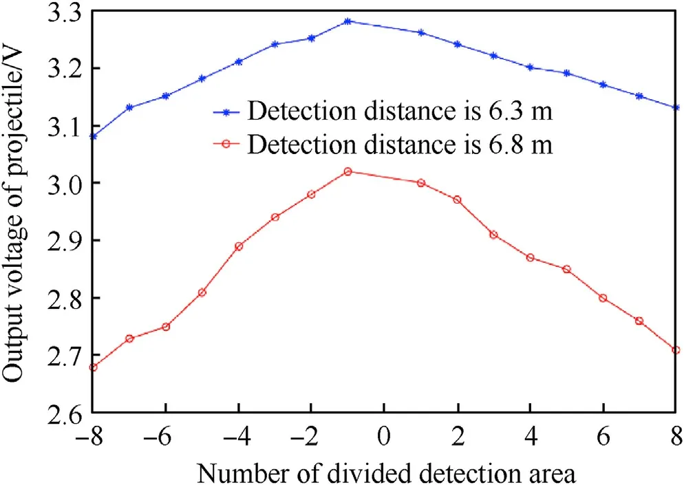
Fig.11. The changing curve of output voltage of projectile at different detection areas.
In the second round of the tests,in order to explain the different detection sensitivities of the photoelectric detection target in different test areas at the same detection distance, the rifle was used to shoot in central, left and right detection areas of the photoelectric detection target,namely,the numbers of detection areas are -1 to 1, - 2 to - 8, and 2 to 8, respectively. The specific implementation is as follows: the shooting height of the rifle is about 6.7 m,and the shooting position starts from the center of the detection screen.Since the width of unit detection area divided by the detection screen is the same, the projectile moves to the left about 0.15 m each time.The moving distance is half of the width of each unit detection area in order to ensure that the projectile can pass through the detection area, and verify it by the coordinate position on the wooden target. The output voltage of projectile of the system at each detection area is recorded. Then the shooting height of the rifle is increased to 7.2 m and the output signal of the system at each detection area is recorded, as shown in Fig.11.
It can be seen from Fig.11 that when the shooting height of the rifle is the same and the projectile is shoot in the left and the right detection areas with the optical axis of the optical lens as the center,the amplitude of the output signal is approximately the same,with a slight difference.The main reason is that the flight attitude of the projectile is different when it passes through the detection area,and the position is not completely consistent when the projectile passes through the symmetric detection area during the test process, causing the distance between the projectile and the optical lens to be slightly different. When the shooting position moves to both sides of the detection area,the distance of the projectile acting on the optical lens also increases and the amplitude of the output signal of the system decreases significantly. For the photoelectric detection target, when the shooting height is 7.2 m and the diameter of the projectile is 7.62 mm, the distance between the projectile and the optical lens is close to 6.8 m in the center of the detection area. Although the output voltage of projectile is larger than the signal of the system itself, the detection sensitivity of the system is lower. When the shooting position moves 2.59 m to the left and is in the edge detection area, the distance between the projectile and the optical lens is about 7.3 m, which is more than 900 times the diameter of the projectile and the amplitude of the output voltage of projectile is extremely small.In this test state,the detection sensitivity of the system is lower than the critical value of the detection sensitivity that the system can capture the target,which again shows that the detection sensitivity of the entire detection area of the photoelectric detection target is inconsistent.Fig. 12 shows the schematic diagram of projectile imaging with different detection distances.
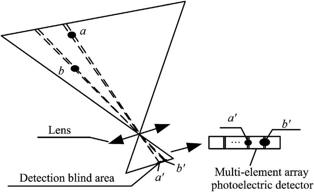
Fig. 12. The schematic diagram of projectile imaging with different detection distances.
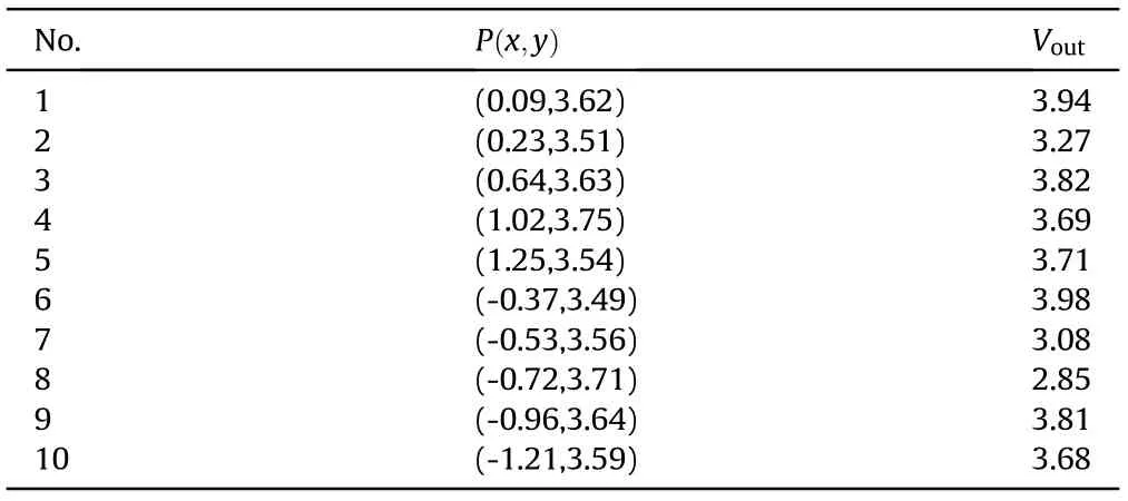
Table 1 The test data of photoelectric detection target without gain compensation.
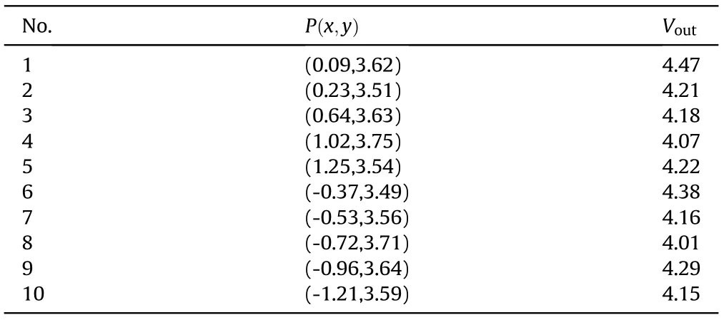
Table 2 The test data of photoelectric detection target with gain compensation.
In Fig.12,a and b express the projectiles with the same diameter,the detection distances of a and b are about 3 m and 1.4 m,respectively, while aand brepresent the imaging spots of projectiles a and b, respectively. From Fig.12, it can be observed that the influence of the blind area on the system detection is more significant when the detection distance is higher and the area of the imaging spot is smaller.
In order to further verify the feasibility of the supplementary measures for detecting blind area, the third round of the tests is carried out. Two photoelectric detection targets are used, whose structures, optical lenses and photoelectric detectors are completely same. The difference between two photoelectric detection targets is that the signal processing module of one photoelectric detection target adopts fixed gain mode,while that of the second photoelectric detection target adopts self-adaptive gain mode. In the process of layout, the two photoelectric detection targets are placed in parallel with a distance of about 1 m.The two photoelectric detection targets are adjusted to make the detection screen parallel,and the center of the detection screens is parallel to the ballistic direction, the detection distance is determined when the thickness of the detection screen is greater than the length of the projectile,the air gun is used to shot,the diameter and length of the bullet are 4.5 mm and 7.62 mm respectively.The position of the projectile passing through the wooden target is recorded, the detection distance is determined and the output signal peak of each projectile is obtained. Table 1 is the test data of photoelectric detection target without gain compensation, and Table 2 is the output signal peak value recorded based on the gain compensation method proposed in this paper, Vis the output voltage of projectile.The coordinate data unit in the table is meter,and the output voltage data unit is volt.
From the data in Tables 1 and 2, it can be seen that at the coordinate position of(0.23,3.51),(-0.53,3.56)and(-0.72,3.71), the output signal amplitude with gain compensation method is significantly larger than that without gain compensation,and the coordinate position with obvious signal difference are consistent with the results in Figs.7-9;at the same time,it is also found from Table 2 that the output voltage of the detection blind area is close to that of the corresponding detection non-blind area,the results fully show that the detection sensitivity model and multi-channel gain compensation measures can improve the detection performance of the photoelectric detection target.
4. Conclusions
In this paper, the calculation model of detection sensitivity of photoelectric detection target is established by using multielement array photoelectric detectors. Since the multi-element array photoelectric detectors have detection blind areas, the detection screen is divided into many small detection areas and the angle between the central axis of each small detection area and the optical axis of the optical lens is calculated.According to the angle,the calculation function of the luminous flux of the single-element photoelectric detector is established.Based on the optical lens edge effect and the detection blind area, the detection sensitivity is derived and the output voltage amplitude is obtained. The experiments are conducted in different detection distances and different detection areas. The obtained test results show that the multiple area detection sensitivity of the photoelectric detection target established in this paper is scientific and feasible. Based on the strategy of the gain compensation of single-element photoelectric detector, this method improves the detection sensitivity of photoelectric detection target under a certain detection distance, which provides a theoretical basis for the stability test of new weapons.However, further research is required to improve the detection sensitivity of the photoelectric detection target when the detection distance is large.
There are no conflicts of interest,and it has not been submitted elsewhere for consideration of publication.
This work has been supported by Project of the Xi’an Science and Technology Innovation talent service enterprise project(No.2020KJRC0041), National Natural Science Foundation of China(No.62073256), and Key Programs of Shaanxi Science and Technology Department (No.2020GY-125).
杂志排行
Defence Technology的其它文章
- Research on DSO vision positioning technology based on binocular stereo panoramic vision system
- Dynamics of luffing motion of a hydraulically driven shell manipulator with revolute clearance joints
- Blast performance of layered charges enveloped by aluminum powder/rubber composites in confined spaces
- Chemical design and characterization of cellulosic derivatives containing high-nitrogen functional groups: Towards the next generation of energetic biopolymers
- Applicability of unique scarf joint configuration in friction stir welding of AA6061-T6: Analysis of torque, force, microstructure and mechanical properties
- Accurate analysis of limiting human dose of non-lethal laser weapons
