A novel model for the proppant equilibrium height in hydraulic fractures for slickwater treatments
2022-03-30ZhongWeiWuChuanZhiCuiYinZhuYeXiangZhiChengJapanTriveiShuiQingShanLuYinQian
Zhong-Wei Wu ,Chuan-Zhi Cui ,* ,Yin-Zhu Ye ,Xiang-Zhi Cheng ,Japan Trivei ,Shui-Qing-Shan Lu ,Yin Qian
a College of Petroleum Engineering,China University of Petroleum (East China),Qingdao,266580,Shandong,China
b Key Laboratory of Unconventional Oil & Gas Development (China University of Petroleum (East China)),Ministry of Education,Qingdao,266580,Shandong,China
cResearch Institute of Petroleum Exploration & Development,PetroChina,Beijing,100083,China
d School of Mining and Petroleum,Department of Civil and Environmental Engineering,University of Alberta,Edmonton,AB,T6G 2R3,Canada
Keywords:Equilibrium height Proppant settling Fracture width Slickwater Shale and tight reservoirs
ABSTRACT The proppant equilibrium height is the basis of investigating proppant distributions in artificial fractures and has a great significant influence on hydraulic fracturing effect.There are two shortcomings of current research on proppant equilibrium heights,one of which is that the effect of fracture widths is neglected when calculating the settling velocity and another of which is that the settling bed height is a constant when building the settling bed height growth rate model.To fill those two shortcomings,this work provides a novel model for the proppant equilibrium height in hydraulic fractures for slickwater treatments.A comparison between the results obtained from the novel model and the published model and experimental results indicates that the proposed model is verified.From the sensitivity analysis,it is concluded that the proppant equilibrium height increases with an increasing proppant density.The proppant equilibrium height decreases with an increase in the slickwater injection rate and increases with an increase in the proppant injection rate.The increase in proppant diameter results in an increasing the friction factor,which makes proppant equilibrium heights decrease.Meanwhile,the increase in proppant sizes results in an increase in proppant settling rates,which makes the proppant equilibrium height increase.When the effect of the proppant diameter on settling rates is more significant than that on friction factors,the equilibrium height increases with an increasing proppant size.This work provides a research basis of proppant distributions during the hydraulic fracture.
1.Introduction
Hydraulic fracture technology for slickwater treatments has been widely used for the economic development of unconventional reservoirs,such as shale and tight reservoirs(Wang et al.,2020;Wu et al.,2019,2020,2021a,2021b).Slickwater can be pumped down the well-bore as fast as 160 m3/min.However,without using the slickwater the top speed of pumping is around 95 m3/min.Besides,the slickwater is cheaper than other kinds of fracturing fluids.During the hydraulic fracturing in shale or tight reservoirs,the proppant is pumped into the artificial fracture together with slickwater.Due to the proppant gravity,the proppant settles to the fracture bottom and forms a settling bed.Therefore,the fracture could be divided into a proppant settling bed in the bottom of fractures and a proppant flow layer in the upper of fractures(Patankar et al.,2002;Hu et al.,2018a).When the reduction rate of proppant settling bed height caused by washing-out is equal to the growth rate caused by settling,the height of proppant settling bed is the proppant equilibrium height (Hu et al.,2018a).The determining for proppant equilibrium heights has key significance for investigating the proppant transport behavior.Currently,there are three group models to simulate the particle transportation behavior in hydraulic fractures,one of which is the Eulerian model(Ariyaratne et al.,2016;Kong et al.,2016;Hu et al.,2018b).In the Eulerian model,the proppant transport in the fracture can be divided into two parts:proppant settling and horizontal transport.The proppant equilibrium height is the key parameter when studying the proppant settling in the fracture.
Currently,there are many investigations on the proppant or grain settling rate in the fracturing fluid or water.From the published work of Ferguson and Church(2004),it is concluded that the process of grain settling can be divided into three stages,which are the Stokes stage,transition stage,and Newtonian stage.When the Reynolds number is less than 1,the grain settling belongs to the Stokes stage and the settling rate of a grain can be calculated by the Stokes law(Stokes,1851).When the Reynolds number is larger than 1000,the grain settling belongs to the Newtonian stage and the settling rate formula can be seen in the work of Rijin(1993).At the Newtonian stage,the turbulent drag force is the main flowing resistance.The grain settling belongs to the transition stage when the Reynolds number is between 1 and 1000.Ferguson and Church(2004) proposed a formula for calculating settling rate by a dimensionless analysis method,which can be used to calculate grain settling rates at the Stokes stage,transition stage and Newtonian stage.However,in the work of Ferguson and Church(2004),the effect of fracture widths on settling rate is not taken into consideration.Liu and Sharma (2005) conducted particle settling experiments in an unbounded fluid and various bounded fluid.From the work of Liu and Sharma (2005),it is concluded that the effect of fracture walls on grain settling is insignificant until the fracture width is 10%-20%larger than the particle diameter.In the actual situation of the hydraulic fracturing in shale or tight reservoirs,the width of fracture toes is very small and meets the condition where the fracture width is 10%-20%larger than the particle diameter.Therefore,the effect of fracture widths on the proppant settling has to be taken into consideration.Meanwhile,the settling rate of proppant is affected by the proppant concentration due to the interaction between proppants(Dunand and Soucemarianadin,1985;Tomac and Gutierrez,2015).With considering the effects of the proppant concentration and fracture width,we have proposed a comprehensive model for determining proppant settling rate,which is utilized to calculate the settling rate in this work(Cui et al.,2020).
The proppant equilibrium height was attached great attention to petroleum engineers many years ago.Wang et al.(2003) firstly proposed an explicit bi-power correlation of dimensionless proppant equilibrium heights.This proposed correlation can faithfully describe the proppant washout and settling behavior in a slot under a wide variety of conditions.However,the proppant settling was conducted in the water instead of fracturing fluids,which indicated that the work of Wang et al.(2003)cannot be directly utilized to the scenario where the proppant settling occurs in the slickwater.Besides,the correlation could not reveal the effect mechanism of factors (such as viscosity,fracturing fluid injection rate) on equilibrium heights.Alotaibi and Miskimins (2018) proposed a statistical model for the proppant equilibrium height with considering the effect of proppant concentrations.In their work,the proppant transport behavior underwent four stages,each of which had a distinct proppant-transport mechanism,dune-height-buildup rate,and dune height.However,the effect of fracture widths was neglected and the proposed statistical model cannot reveal the effect mechanism of related factors.Hu et al.(2018a) built a mathematical model for the proppant equilibrium height,which can be used to quantify the effects of both proppant properties and fluid properties on equilibrium height.In their work,the effect of fracture widths on proppant settling rates is ignored,and the settling bed height is a constant when building the calculation formula of settling bed height growth rates.However,the settling bed height increases with the proppant settling in actual scenarios.
From the literatures review stated above,current studies of proppant equilibrium height have two shortcomings,one of which is that the effect of fracture widths is neglected when calculating the settling velocity and another of which is that the settling bed height is a constant when building the settling bed height growth rate formula.To fill this gap,a novel model for the proppant equilibrium height in hydraulic fracture for slickwater treatments is built.Additionally,the effect of factors on equilibrium heights is analyzed,especially for the fracture width and proppant size.
2.A novel model for proppant equilibrium heights
2.1.The growth rate of proppant settling beds
From our previous work(Cui et al.,2020),the proppant settling rate,which considers the effects of the fracture width and proppant concentration,is obtained as follows.
When the ratio of the proppant diameter to fracture width is less than 0.9,the settling rate is as follows (Cui et al.,2020),

When the ratio of the proppant diameter to fracture width is more than 0.9,the settling rate is as follows (Cui et al.,2020),

whereVsis the proppant settling rate with considering the effects of the proppant concentration and fracture width,m/s;Cis the proppant concentration(dimensionless);α is a constant related to the flow stage.According to the work of Lewis et al.(1949),Barnea and Mizrahi (1973),we can know that the value of α is between 4.56 and 5 when the flow is at the Stokes flow stage.The value of α is between 2.3 and 2.65 at the Newtonian stage.μsis the fluid viscosity,Pa s;Dis the proppant diameter,m;Wis the fracture width,m;Vssis the settling rate of a single proppant,m/s,the expression of which is as follows(Ferguson and Church,2004;Cui et al.,2020;McClure and Kang,2017),

wheregis the gravitational acceleration,m/s2;ν is the Kinematic viscosity of slurry(m2/s),which is a mixture of the fracturing fluid and proppant;C1is a constant related to the properties of particles(Raudkivi,1990),which equals 18 in accordance to Ferguson and Church’s work (2004);C2is the drag coefficient asymptotic value.From Cheng’s work (1998),C2equals 0.4 for smooth surface particles and 1 for natural particles.Ris the submerged specific gravity,the calculating formula of which is as follows (Ferguson and Church,2004;Cui et al.,2020),

where ρpand ρsare the density of the proppant and fluid,kg/m3,respectively.
When the concentration of the proppant in slickwater isC,the volume of the particles which settle per unit area in a time dtis equal toCVsdt.The porosity of proppant settling bed is 1-Cmax.The corresponding proppant settling bed height is dHb=CVsdt/[1-(1-Cmax)],rearranging which we can get the growth rate of the proppant settling bed height (Gu and Hoo,2014,2015,2015;Schols and Visser,1974),

where dHbis a height increment of the proppant settling bed at time dt;Cmaxis the maximum proppant concentration in the fracturing fluid,m3/m3.
Eq.(5) contains a hypothesis that the proppant settling bed height is a constant when the proppant settles.That is contrary to the actual situation.Therefore,a novel growth rate model for the proppant settling bed height,which considers the increase in the height of the proppant settling bed caused by the proppant settling,should be built.
Fig.1 is a schematic diagram of a two-layer model for proppant transporting in an artificial fracture.The fracture can be divided into two parts (Kamp and Rivero,1999;Ramadan et al.,2001;Wu et al.,2014),which are the proppant flow layer and proppant settling bed.The slurry flows in the proppant flow layer.The proppant settling bed can be seen as a porous medium which is composed of proppants (Hu et al.,2018a).According to the mass conservation principle,namely the proppant increment at the proppant settling bed equals the reduction of proppant in the proppant flow layer caused by settling,we can obtain

where dHsis the height of slurry unitA,m2;Δsis the area ofAorB,m2.
Due to the even distribution of the proppant in the flow layer,according to the mass conservation,we can obtain

whereNis the total proppant number in slurry unitA.
According to the line concentration definition,which is the length occupied by the proppant in a unit length,we can obtain the expression of the proppant line concentration as follows,

whereClineis the proppant line concentration,dimensionless.
Combining Eqs.(7)and(8),the expression of the proppant line concentration can be simplified,as follows,
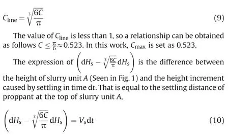
Combining Eqs.(6) and (10),we can get a novel expression of the growth rate of the proppant settling bed height by eliminating the item of dHs.

By comparing Eq.(5)and Eq.(11),we can know that the growth rate of the proppant settling bed height is underestimated when the increase of the proppant settling bed height caused by proppant settling is neglected.
2.2.Proppant equilibrium heights
In this sub-section,a method for determining the proppant equilibrium height is presented.The proppant settling bed height is the equilibrium height when the reduction rate of proppant settled bed height caused by washing-out is equal to the growth rate of that caused by settling.

where dHwis the washout height of proppant settling beds for a time dt.

Fig.1.The schematic diagram of a two-layer model for proppant transporting in an artificial fracture.A indicates the slurry unit in the proppant flow layer;B indicates the proppant settling bed unit corresponding to the slurry unit A.
For the proppant settling bed unitB(seen in Fig.1),we can get the momentum conservation equation in the horizontal direction.

where τ is the shearing force of the proppant flow layer on settling bed,N/m2;V1andV2are respectively the proppant flow velocity in the settling bed and proppant flow rate after being wash away from the proppant settling bed,m/s;mbis the proppant mass of unitBin the proppant settling bed (kg) and the expression is

where ρbis the proppant settling bed density,kg/m3.The expression of the proppant settling bed density is as follows,

By Eqs.14 and 15,Eq.(13) can be simplified as

The proppant settling bed is immovable,so the flow velocity of the proppant in the settling bed (V1)equals zero.And the value ofV2equals to the equilibrium velocity (Ve),which is the slurry flow rate,when the equilibrium height reaches.Kis an experimental factor,which is less than 1 and is utilized to describe the relationship betweenV2andVe.Therefore,when the equilibrium state of the proppant bed height reaches,Eq.(16) can be rearranged as follows,

Substituting Eqs.(16) and (17) into Eq.(12),we can get the equilibrium velocity expression as follows,

According to the published work(Peker and Helvaci,2008),the shearing force can be calculated by the following formula,

where ρsluis the slurry density,kg/m3,ρslu=(1 -C)ρs+Cρp;Vsluis the flow rate of slurry in the proppant flow layer,m/s,Vslu=Vewhen the equilibrium height reaches;fis the friction factor.When the equilibrium height reaches,Eq.(19) can be rearranged

The friction factor can be calculated by the following equation(Doron et al.,1987),

whereReis the Reynolds number of fluid flow in the proppant flow layer;Dhis the hydraulic diameter of the cross-section of hydraulic fractures,m.
The expression of Reynolds number is (Hu et al.,2018a,2018b,2018b)

Fig.2.The schematic diagram of the vertical cross-section of a hydraulic fracture.

From the works of Hu et al.(2018a)and Adachi et al.(2007),we can obtain the expression of slurry viscosity as follows,

When the equilibrium height reaches,Vslu=Ve.Therefore,Eq.(22) can be rearranged.

The vertical cross-section of a hydraulic fracture can be seen in Fig.2.Based on the definition of the hydraulic diameter,the expression of which is

whereLupis the height of the proppant flow layer,m.When the proppant equilibrium height reaches,Lup=Hf-He(HfandHerespectively are the fracture height and proppant equilibrium height,m.).
Substituting Eq.(20)into Eq.(18),we can obtain the equilibrium height expression.

When the proppant equilibrium height reaches,the relationship between the proppant equilibrium height and fracture height is

whereQpandQsare the proppant injection rate and fluid injection rate,respectively,m3/s.
When the fracturing fluid loss occurs,the fluid losses into the reservoir.However,the proppant does not invade into the reservoir.Therefore,we introduce a loss rate of the fracturing fluid,which is the ratio of the loss volume of fracturing fluid to the total fracturing fluid volume,to consider the effect of fracturing fluid losses.The expression of the loss rate is as follows,

where γ is the loss rate of the fracturing fluid,dimensionless;Qslossis the loss volume of fracture fluids and can be determined by indoor experiments,m3/s.
From Eq.(28),we can obtain the remaining fracturing fluid volume after fracturing fluid loss,

By Eqs.(27) and (29),we can obtain the relationship between the proppant equilibrium height and fracture height when the effect of fracturing fluid loss is taken into consideration.

By Eq.(26) (29),Eq.(30) can be rearranged as follows,

When the effect of the fracturing fluid loss is taken into consideration,the relationship among the proppant concentration in the proppant flow layer,proppant injection rate,and the injection rate of slickwater is as follows,

Substituting Eq.(32)into Eq.(31),we can obtain the expression of proppant equilibrium heights.

The dimensionless proppant equilibrium height is defined as the ratio of the proppant equilibrium height to the fracture height.Therefore,we can obtain the dimensionless proppant equilibrium height as follows,

Substituting Eq.(33) into Eq.(34),the dimensionless proppant equilibrium height is rearranged as follows,
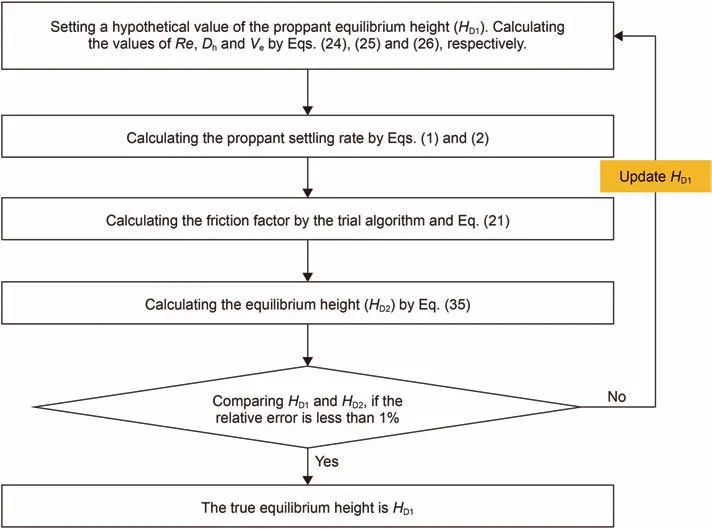
Fig.3.The flow chart to solve the proppant equilibrium height.

Since the friction factor is related to the proppant equilibrium height,Eqs.(33) and (35) are the implicit expression for the proppant equilibrium height.The trial algorithm is utilized to solve the novel model.The flow chart to solve the proppant equilibrium height is seen in Fig.3.From the flow chart,the procedures are as follows,
Step 1:Setting a hypothetical value of the proppant equilibrium height (HD1).Calculating the values ofRe,DhandVeby Eqs.(24)-(26),respectively.
Step 2:Calculating the proppant settling rate by Eqs.(1)and(2)
Step 3:Calculating the friction factor by the trial algorithm and Eq.(21)
Step 4:Calculating the equilibrium height (HD2) by Eq.(35)
Step 5:Carrying a comparison between the proppant equilibrium height (HD2) obtained in step 4 and the hypothetical value(HD1) obtained in step 1.If the relative error is less than 1%,we recognize that the equilibrium height in step 1 is equal to the true equilibrium height.Otherwise,other hypothetical value of the proppant equilibrium height should be assigned.And repeat steps 1 to 5.
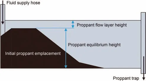
Fig.4.The schematic diagram of an experimental setup used in the work of Wang et al.(2003).

Fig.5.A comparison between the results calculated by the proposed model and experimental results published by Wang et al.(2003).
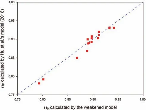
Fig.6.A comparison between the results calculated by the weakened model and Hu et al.’s model (2018a).
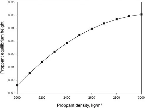
Fig.7.The effect of the proppant density on the poppant equilibrium height.
3.Model verification and case studies
3.1.The verification of model
In order to verify the model,we compare the results calculated by the proposed model with the experimental results published by Wang et al.(2003).In the work of Wang et al.(2003),an experimental setup (Fig.4) is used to study the proppant transport behavior.
By the experimental setup,Wang et al.(2003) conducted a series of experiments of proppant transport in water with various fracture injection rate and proppant injection rate.The assigned parameters used and the experimental results (Wang et al.,2003)are shown in Table 1.

Table 1 The assigned parameters and experimental results in the work of Wang et al.’s (2003).

Table 2 Parameters used in case studies.

Fig.8.The effect of the slickwater viscosity on the proppant equilibrium height.
Using the parameters shown in Table 1 and the proposed model,the proppant equilibrium height is calculated.The comparison between the results calculated by the model and experimental results published by Wang et al.(2003)is performed and shown in Fig.5.Seen from Fig.5,the results calculated by the proposed model are consistent with the experimental results published by Wang et al.(2003).The relative error is less than 4.2%.And the average relative error is only 3.01%.
In order to further verify the proposed model,a comparison between the result calculated by the weakened model and that calculated by Hu et al.’s model (2018) is presented.The weakened model is obtained from the proposed model by ignoring the influence of variable settling bed height on the equilibrium heights when calculating the growth rate of proppant settling bed heights.In the work of Hu et al.(2018),the effect of fracture width on proppant settling rate is ignored.Since the effect of fracture walls on grain settling is not significant until the ratio of the proppant size to fracture width is larger than 0.83 (Tomac and Gutierrez,2015).Therefore,the effect of fracture widths on the proppant settling rate can be ignored when the ratio of the proppant size to fracture width is 0.076,which is assigned in Table 1.A comparison between the results calculated by the weakened model and that calculated by Hu et al.’s model(2018a) is conducted and shown in Fig.6.It can be seen from Fig.6 that the results calculated by the weakened model and Hu et al.’s model show a great consistency.The relative error is less than 4.5%and the average relative error is only 2.93%.From the stated above,it is concluded that the proposed model can be utilized to evaluate the proppant equilibrium height,accurately.

Fig.9.The effect of the proppant diameter on proppant equilibrium height.
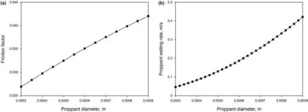
Fig.10.The effect of the proppant diameter on (a) friction factor and (b) proppant settling rate.

Fig.11.The effect of the slickwater injection rate on proppant equilibrium heights.
3.2.Sensitivity analysis of influence factors
In the sub-section,we conduct many case studies to investigate the effects of key parameters on the proppant equilibrium height.The parameters used in case studies are shown in Table 2.
3.2.1.Effect of the proppant density
In this subsection,we investigate the effect of the proppant density on proppant equilibrium height.The parameters used in the study are listed in Table 2(Case 1).The results are seen in Fig.7,from which an increasing proppant density results in the increase in the proppant equilibrium height.The reason for the scenario is that a larger proppant density is corresponding to a higher proppant settling rate,which results in a larger growth rate of proppant settling bed heights.Meanwhile,a larger proppant density results in a smaller proppant wash-out rate.Therefore,the proppant equilibrium height increases when the proppant density increases.
3.2.2.Effect of the slickwater viscosity
In this part,the effect of the slickwater viscosity on proppant equilibrium heights is presented.The inputting parameters are listed in Table 2(Case 2).The detailed results can be seen in Fig.8.From Fig.8,the proppant equilibrium height decreases with an increasing fracturing fluid viscosity.Meanwhile,the proppant equilibrium height decreases with the increase in the fracturing fluid density when the fracturing fluid viscosity is constant.It is due to the carry ability of fracturing fluids becoming significant when the fracturing fluid viscosity and density increase.This results in the decrease in the growth rate of proppant settling beds.Therefore,the increases in the fracturing viscosity and density result in a decreasing proppant equilibrium height.
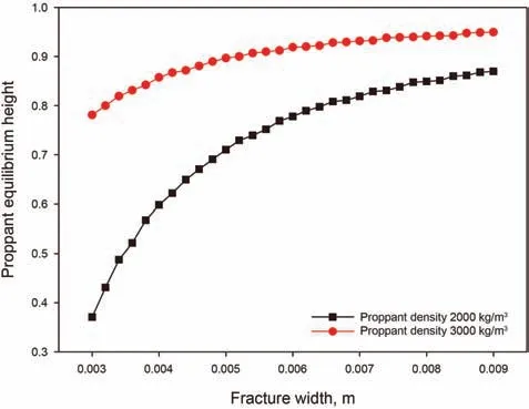
Fig.12.The effect of the fracture width on the proppant equilibrium height.
3.2.3.Effect of the proppant diameter
The effect of the proppant diameter on proppant equilibrium heights is investigated.The inputting parameters can be seen in Table 2 (Case 3).The calculation results are seen in Fig.9.From Fig.9,when the fracture width is constant,the increase in proppant diameters results in an increase in the proppant equilibrium height.When the proppant diameter is constant,the proppant equilibrium height increases with the increase in fracture widths.The reasons for this scenario are seen in below.
The effect of the proppant diameter on friction factors is seen in Fig.10a.The inputting parametersWandHDare 0.006 m and 0.8,respectively.Other inputting parameters are listed in Table 2(Case 3).Seen from Fig.10a,when the proppant diameter increases,the friction factor increases,which results in the shearing force of the proppant flow layer to proppant settling bed becoming significant.Therefore,the proppant equilibrium height decreases.However,the proppant size not only affects the friction factor but also the proppant settling rate.By Eq.(1) (2) and (3),we investigate the effect of the proppant size on settling rates(Fig.10b).From Fig.10b,it is concluded that the increase in proppant sizes results in an increasing proppant settling rate,which leads to the increase in proppant equilibrium heights.When the effect of the proppant diameter on settling rates is more significant than that on friction factors,the proppant equilibrium height increases with the increase in proppant sizes.

Fig.13.The effect of variable settling bed height on the equilibrium height when calculating the proppant settling rate.
3.2.4.Effect of the slickwater injection rate
In this section,we study the effect of the slickwater injection rate on the proppant equilibrium height.The parameters used in the study are listed in Table 2(Case 4).The detailed results are seen in Fig.11.Seen from Fig.11,the proppant equilibrium height decreases with an increasing fracturing fluid injection rate and increases with an increasing proppant injection rate.When the fracturing fluid injection rate increases,the shearing force of the proppant flow layer to proppant settling beds increases.This results in the decrease in proppant equilibrium heights.When the proppant injection rate increases,the proppant concentration increases,which results in the decrease in the proppant settling rate.However,the increase in proppant concentration results in an increasing line concentration.The effect of the proppant injection rate on line concentrations is more significant than that on settling rates.Therefore,the increase in proppant injection rates indicates an increase in proppant equilibrium height.
3.2.5.Effect of the fracture width
In this section,we study the effect of the fracture width on the proppant equilibrium height.The parameters used in the study are listed in Table 2 (Case 5).The detailed results are seen in Fig.12.Seen from Fig.12,the proppant equilibrium height increases with an increasing fracture width.This is due to that a decrease in the slurry flow rate makes the shearing force of the proppant flow layer to proppant settling beds become insignificant.
3.2.6.The effect of variable settling bed height on the equilibrium heights when calculating the proppant settling rate
Using the data in Table 2(Case 3)and the weakened model,we calculate the dimensionless proppant equilibrium heights with/without considering various settling bed height effect.The weakened model is obtained from the proposed model by ignoring the influence of variable settling bed height on the equilibrium height when calculating the proppant settling rate.The detailing is described in Fig.13.From Fig.13,it is concluded that the variation of settling bed heights has a critical effect on the proppant equilibrium height.The dimensionless proppant equilibrium height with considering various settling bed height effect is larger than that without considering various settling bed height effect.
4.Conclusions
(1) A novel model for the proppant equilibrium height in hydraulic fractures for slickwater treatments is proposed.The results calculated by the novel model have a good consistency with experimental data and the results calculated by the published model.The proposed model overcomes two shortcomings of current works of proppant equilibrium heights,one of which is that the effect of fracture widths is neglected when calculating the settling velocity and another of which is that the settling bed height is a constant when building the settling bed height growth rate model.
(2) An increasing proppant density indicates an increasing proppant settling rate and a decreasing proppant wash-out rate.Therefore,the proppant equilibrium height increases with an increasing proppant density.The increases in the slickwater viscosity and density result in a decrease in the growth rate of proppant settling beds,which indicates the decrease in proppant equilibrium heights.The proppant equilibrium height decreases with an increase in the slickwater injection rate and increases with an increase in the proppant injection rate.
(3) When the proppant diameter increases,the friction factor increases,which results in the shearing force of the proppant flow layer to proppant settling bed becoming significant.Thus the proppant equilibrium height decreases.While the increase in proppant sizes results in an increase in proppant settling rates,which makes the proppant equilibrium height increase.When the effect of the proppant diameter on settling rates is more significant than that on friction factors,the equilibrium height increases with an increasing proppant size.
(4) The proposed novel model for the proppant equilibrium height does not consider the effect of fracture surface properties,which is our future work.
Acknowledgments
The work supported by the National Natural Science Foundation of China (No.51974343),Independent Innovation Scientific Research Project (science and engineering) of China University of Petroleum (East China) (No.20CX06089A) and Qingdao Postdoctoral Applied Research Project(No.qdyy20200084).
杂志排行
Petroleum Science的其它文章
- Reduction of global natural gas hydrate (NGH) resource estimation and implications for the NGH development in the South China Sea
- Evaluation of natural gas hydrate resources in the South China Sea by combining volumetric and trend-analysis methods
- The influence of water level changes on sand bodies at riverdominated delta fronts:The Gubei Sag,Bohai Bay Basin
- Source of silica and its implications for organic matter enrichment in the Upper Ordovician-Lower Silurian black shale in western Hubei Province,China:Insights from geochemical and petrological analysis
- Influence of structural damage on evaluation of microscopic pore structure in marine continental transitional shale of the Southern North China Basin:A method based on the low-temperature N2 adsorption experiment
- Application of multi-attribute matching technology based on geological models for sedimentary facies:A case study of the 3rd member in the Lower Jurassic Badaowan Formation,Hongshanzui area,Junggar Basin,China
