A Novel Flexible Antenna at Very High Frequency Band for On-Body Applications
2022-03-03AbhishekKandwalHuajieTangPengfeiAoKunWangJingzhenLiYuhangLiuToboreIgbeZedongNie
Abhishek Kandwal,Huajie Tang,Pengfei Ao,Kun Wang,Jingzhen Li,Yuhang Liu,Tobore Igbe,Zedong Nie
Abstract:This paper proposes a novel flexible antenna design operating at very high frequency(VHF) band for on-body applications such as human body communication (HBC).The antenna consists of back-to-back E-shaped fractal and complimentary structures designed over a thin flexible substrate.The overall design working on the principle of fractal geometries and capacitive coupling is highly beneficial to achieve better antenna characteristics even at low frequencies around 35 MHz–45 MHz that are being used for HBC application.The proposed antenna obtained a large bandwidth of around 10.0 MHz in air and a bandwidth of around 8.0 MHz during on-body operation.The antenna has been tested in three different scenarios viz.air,on-body single antenna and on-body communication using two antennas.The insertion loss is reduced to a minimum in all three scenarios,which is quite beneficial for better signal transmission.The size miniaturization with high flexibility in such low frequencies has also been achieved in the paper that makes the proposed design suitable for human body communication applications.
Keywords:antenna;very high frequency (VHF);human body communication (HBC);bandwidth;loss;flexible
1 Introduction
Recent years have seen tremendous interest in low megahertz frequencies due to advantages like low losses,low power,low power consumption,etc.Intra-body communication (IBC) or human body communication (HBC) presents a promising solution for the body area networks (BAN),which uses human body as the transmission medium for transmission of information. HBC provides a novel method for transferring healthcare data [1−4].This kind of transmission requires low losses due to interference from several adverse factors.Thus,the implementation of intra-body system with better transmission communication performance is required. However,this field still requires lots of improvements in terms of loss improvements,power consumptions,signal noise,attenuations,bandwidth,gain,signal leakage,secure transmissions,size miniaturization,etc.,for enhanced communication performance. The communication between the sensors placed/fixed over the human body can be achieved using wired or wireless transmission techniques [5−8].Nevertheless,looking at the onbody communication medium,wired connection is surely not a good option.Wired connection always has the problems of connection breaks,and higher attenuations.On this behalf,wireless connection suits the best for communication applications such as for medical purposes [9−12]. In[13−15],dielectric properties of biological tissues have been studied well in detail.
Radio frequency (RF) techniques constitute one branch of the potential techniques for human centric data transmission.RF techniques are susceptible to electromagnetic interferences,radiation leakages,low bandwidth,etc. On-body communication further leads to significant losses and attenuation.RF technique radiates the signal using an antenna [16−28].Therefore designing a proper antenna for such communication is highly desirable.The antenna designed for HBC or intra-body communications should take care of the factors discussed above. Another issue for designing antennas in low megahertz frequencies such as VHF is size miniaturization.Size miniaturization is also a big challenge for low frequency designs.
In this work,a novel flexible antenna/sensor design has been proposed for intra-body or HBC application. The antenna operating at VHF(around 35 – 45 MHz) has achieved size miniaturization along with wide bandwidth,low insertion loss and low transmission signal attenuations.A simulation model has been proposed to analyze and validate the designed characteristics desired for on-body communications. The antenna has been analyzed for three cases viz.single antenna in air,single antenna fixed on body and two antennas fixed on body.In each case,parameters like reflection,transmission,insertion loss,bandwidth,and gain have been discussed.The proposed design is highly suitable for on-body/ intra-body communication systems.
2 Antenna Design
The proposed antenna has been modeled,designed and simulated with the help of a 3D-simulation software Computer Simulation Technology (CST) Studio Suite. The antenna is designed over a thin flexible polyamide substrate with thickness 0.254 mm.The flexible polyamide substrate used has a dielectric constant/epsilon which equals to 3.5 with tangent loss of 0.002 7 and a thermal conductivity of 0.2 W / (K·m).The geometrical configuration and complete design has been shown in Fig.1.The top and bottom layers are copper conductors that serve as antenna design and ground plane respectively.
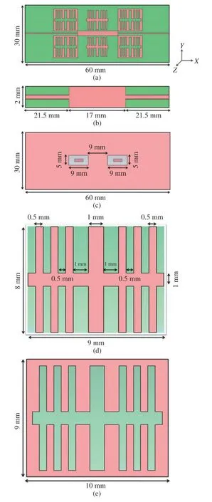
Fig.1 Antenna design:(a) top view of whole antenna;(b)middle microstrip line with center patch;(c) bottom view of slotted ground plane;(d) patch design;(e)complementary patch design
Fig.1(a) shows the top view of antenna design.It consists of two back-to-back E-shaped slotted coupled complementary structures connected with each other using a central rectangular patch design.The whole design is further fed using microstrip lines at both ends through waveguide ports at the same time. An impedance match of 50 Ω is desired as a standard requirement.The overall dimensions of the proposed antenna design are (60 mm × 30 mm) (length ×width).The xyz axes have also been shown in Fig.1 to configure the actual direct of wave propagation.Fig.1(b) shows the central rectangular patch design connected to two microstrip lines as discussed above.The central rectangular patch has dimension of (17 mm × 2 mm) and is connected to the two back-to-back E-shaped structures physically by coupling as well.The microtrip lines at both ends are 21.5 mm in length extending to the edges of the antenna.
Fig.1(c) shows the bottom plane of the proposed antenna.This plane is a ground plane having two well optimized rectangular slots.Each rectangular slot has a dimension of (9 mm ×5 mm) and a copper part in the middle having dimension (4 mm × 2 mm) and is similar to each other.These two slots are placed 9 mm apart.The overall dimension of the ground plane is similar to the top main antenna design i.e.(60 mm × 30 mm).Fig.1(d) shows the top layer patch which forms the E-shaped geometrical structure as shown in Fig.1(a).The overall dimension of this patch shape is (9 mm × 8 mm).It consists of two types of strips,one having width of 1 mm and the other having width of 0.5 mm each.All other dimensions have been shown clearly in Fig.1(d).Fig.1(e) shows the complementary structure of patch shown in Fig.1(d).It is designed by etching out the patch shape out of the conducting layer.The overall dimension of this complementary structure is(10 mm × 9 mm).Combining these complementary structures and non-complementary structure,a complete E-shaped structure has been designed.
Fig.2 shows the standard model of the proposed antenna design.Fig.2(a) shows a general antenna design by mimicking our main proposed antenna design.The figure shows how the antenna has been connected to the two waveguide ports at the two ends of the proposed antenna design.The width of the microstrip line at both ends is kept around 0.35 mm for better impedance match of 50 Ω.The dimensions of these microstrip lines have been optimized well numerically as well by using TXline software.Impedance matching is considered highly significant for such antenna design.Fig.2(b) shows the side view of the layers stacked one over another in sequence.The bottom layer is ground layer/plane which is actually a slotted ground plane as shown above in Fig.1(c).The middle layer is a dielectric substrate layer which is a flexible polyamide substrate in our proposed antenna design.The top layer is the main antenna design.This model in Fig.2(b) is the antenna design in air.As we are also providing the analysis for the proposed antenna when fixed over the body,the multilayer model will be considered.This multilayer model will have other layers of skin and fat above the top layer.
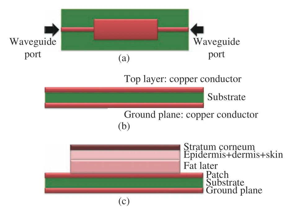
Fig.2 Models:(a) antenna with subminiature version A(SMA) connections on both ends;(b) side view of stacked layers for antenna in air;(c) multilayer model for on-body case (not-to-scale)
Fig.2(c) shows the multilayer model used for the on-body case.The human skin and tissue properties have been mimicked during simulation and made a multilayer model considering the antenna fixed over a particular body part such as an arm.The skin multilayer model has been well explained in [13,24].Epidermis,dermis,and skin layer thickness considered here is 2 mm,and stratum corneum thickness is around 0.02 mm.
3 Results and Discussion
This section shows the results of modeling and simulation for the proposed antenna design in different scenarios.Standard procedure has been adopted for the analysis of the design including several optimizations using 3D electromagnetic wave simulation software.The proposed antenna has been tested for three cases viz.antenna in air,antenna on body,and two antennas on body using different multilayer models. The results have been discussed in detail in Fig.3,Fig.4 and Fig.5.
3.1 Antenna in Air
Fig.3(a) shows the S-parameter result for the antenna tested in air.Reflection (S11) and Transmission (S21) results have been plotted in the respective graph.As can be seen from this graph,antenna is operating at a frequency of 45 MHz with very good return loss of 27 dB.The impedance bandwidth is around 10.0 MHz below–6 dB and around 6.0 MHz below–10 dB.This bandwidth is quite good for such low frequency designs.S21at the same frequency of 45 MHz is–1.9 dB which shows good transmission.It depicts low loss at the operating frequency and good radiation too.
Fig.3(b) shows the graphs for field distribution at the operating frequency of 45 MHz.The graph can be clearly analyzed with most of the energy concentrated around the main antenna patches.The upper part of the figure shows the top view and the bottom part of the figure shows the ground plane view.The ground plane that has slots etched in it is effective in attaining wide bandwidth similar to defected ground antenna principle.Fig.3(c) shows the impedance graph for the antenna in air.It has been observed from this graph that antenna is well matched for 50 Ω impedance at the operating frequency of 45 MHz.The figure shows the real part of impedance while the imaginary part should be close to zero reference line when plotted.
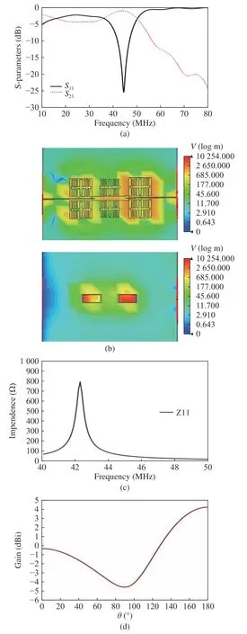
Fig.3 Antenna in air:(a) S-parameters (S11 &S21);(b) E-field distribution;(c) impedance;(d) radiation pattern
Fig.3(d) shows the radiation pattern depicting antenna gain of the proposed antenna in air at the operating frequency of 45 MHz.The graph has been plotted between antenna gain(dBi) in the Y-axis and Theta (°) in the X-axis.As can be seen from the graph,the antenna has provided a high gain of 4.33 dBi.This gain is considered high for so low frequency designs.The antenna further has less back scattering which is good for overall performance of the mentioned antenna.
3.2 Antenna Fixed on Body
In this subsection,the proposed antenna has been tested using a multilayer skin model by mimicking the on-body scenario fixing the mentioned antenna on the body part like an arm.The result sees a few changes while considering the antenna on-body case.The losses are minimal even after attaching the antenna to the multilayer simulation model.
Fig.4(a) shows the S-parameter result for the antenna tested with multilayer skin simulation model.Considering the antenna fixed on the body part,the reflection (S11) and transmission(S21) results have been plotted in the respective graphs.As can be seen from this graph,antenna is now operating at a frequency of 40 MHz with very good return loss of 17 dB.The impedance bandwidth is around 8.0 MHz below–6 dB and around 4.0 MHz below–10 dB.This bandwidth is also good for such low frequency designs.S21at the same frequency of 40 MHz is–2.4 dB which shows very good transmission again.It depicts very low loss at the operating frequency similar to the antenna in air scenario.The frequency shifted to 40 MHz as compared to the antenna in air case because the antenna is now attached to the body thereby increasing the permittivity.This case is now considered as antenna with dielectric medium rather than antenna in free air.
Fig.4(b) shows the impedance graph for the antenna on body.It has been observed from this graph that antenna is well matched for 50 Ω impedance at the operating frequency of 40 MHz.
Fig.4(c) shows the radiation pattern depicting antenna gain of the proposed antenna onbody case at the operating frequency of 40 MHz.As can be seen from the graph,the antenna has provided a high gain of 3.54 dBi.This antenna body case also has less back scattering which is good for overall performance.
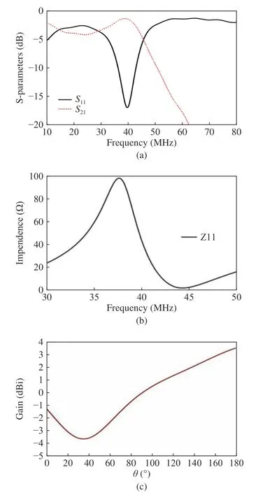
Fig.4 Antenna on-body:(a) S-parameters (S11 &S21);(b) impedance;(c) radiation pattern
3.3 Antenna Fixed for On-Body Communication
In this subsection,the proposed antenna has been tested using a multilayer skin model by mimicking the on-body scenario fixing two similar antennas on the body part like an arm in two different positions.The distance between two antennas considered in the case is 23.5 mm.This distance can also be changed and optimized for analyzing the change in antenna properties.For this case,the results,especially the overall gain of the antenna,have been observed to be improved.The losses are reduced to the minimum.
Fig.5(a) shows the S-parameter result for the fixed antennas tested with multilayer skin simulation model at 23.5 mm distance apart.Considering the antennas fixed on the body at different points,the reflection (S11) and transmission (S21) results have been plotted in the respective graphs.As can be seen from this graph,antenna is now operating at a frequency of 35 MHz with very good return loss of 16 dB.The impedance bandwidth is around 5.0 MHz below–6 dB and around 3.0 MHz below–10 dB.In this case,the frequency has shifted to 35 MHz as compared to the above discussed antenna cases because the two antennas attached the body thereby increasing the permittivity more than the previous case.As the permittivity increases,the resonant frequency decreases which makes it an inversely proportional equation.
Fig.5(b) shows the isolation graph for the antennas on-body case.Since two antennas are placed close to each other,isolation becomes an important parameter to check whether the two antennas are interfering with each other or not.Since the isolation levels are around –78 dB to–100 dB,it can be observed that the antennas are operating without interfering each other.This isolation level obtained is quite high and very good for multi antenna systems on the same platform.Its working principle is similar to array designs or shared aperture antennas where high isolation levels are required to achieve better antenna performance.Fig.5(c) shows the impedance graph for the antenna on body.It has been observed from this graph that antenna is well matched for 50 Ω impedance at the operating frequency of 35 MHz.Fig.5(d) shows the radiation pattern depicting antenna gain of the proposed antenna on-body case at the operating frequency of 35 MHz. As can be seen from the graph,the antenna has provided a high gain of 4.92 dBi with low back scattering which is good for overall performance of the antenna.
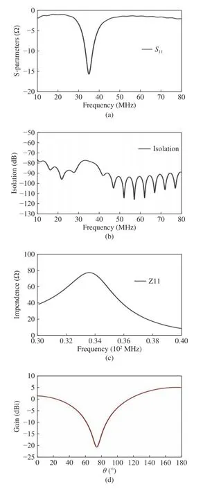
Fig.5 Antennas on body at two positions:(a) S-parameters(S11);(b) isolation between two antennas;(c) impedance;(d) radiation pattern
Tab.1 shows the comparison with other antennas for human body communications at similar or nearby frequencies.A direct comparison is though difficult to analyze since different researchers use different antennas or techniques for measurements at these low megahertz frequencies.
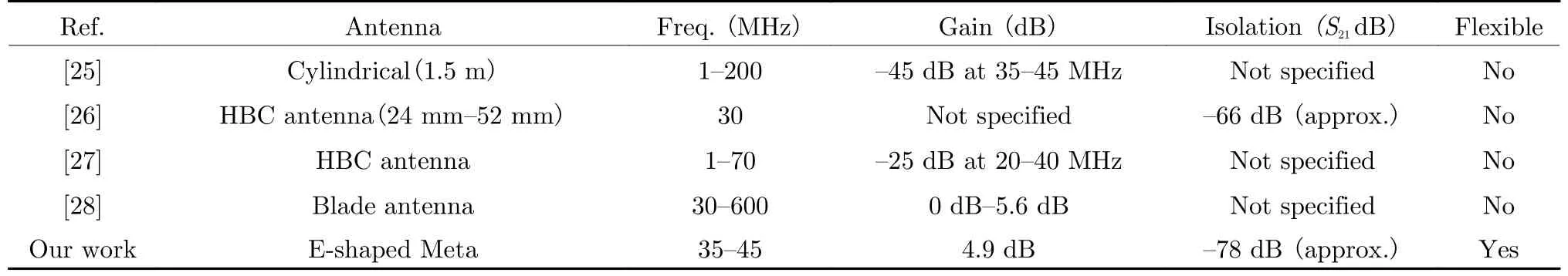
Tab.1 Comparison
4 Discussion
The results discussed above for the proposed novel antenna design for human body communication systems showed their benefits.The novel antenna proposed in the paper has a new metacomplementary structure with a defected ground geometry as compared to the existing simple patch or dipole structures at such low MHz frequencies with large dimensions.This meta-complementary structure on the top helps in achieving higher gain at the resonant frequencies.The defected ground geometry at the bottom helps in realizing a wider bandwidth and further helps in achieving better gain.The proposed antenna is also compact for low MHz frequencies.The conventional antenna design at such low megahertz frequencies is generally very large in size and also consists of simple dipole structures or simple patches.Here in our proposed design,we have designed a new compact meta-complementary antenna that further helps in getting better antenna properties in terms of bandwidth and gain.The flexible nature of the antenna is highly beneficial for on-body testing.When we want to test the antenna over human-body,then the antenna should be compact and also flexible so that it can be easily fixed over the body part without much changes in the results.The proposed antenna will be modified and extended in our future work at system level and will also be tested in real life scenario.
5 Conclusion
A novel flexible VHF antenna has been proposed in this work operating in the frequencies from 35 MHz to 45 MHz.The antenna has been tested in different scenarios such as in air,using single antenna on body with a multilayer model and using two antennas in different positions on body.Various parameters like reflection,transmission,impedance,radiation performance and isolation have been studied and analyzed.The proposed antenna has been observed with good antenna characteristics with large bandwidth,high stable gain,and high isolation which make the design suitable for intra-body applications.
杂志排行

Journal of Beijing Institute of Technology的其它文章
- A Time-Frequency Associated MUSIC Algorithm Research on Human Target Detection by Through-Wall Radar
- Workers’ Cerebrocortical Activity in Hot and Humid Condition:An Electroencephalogram Study
- High-Precision Vital Signs Detection Method Based on Spectrum Refinement and Extended DCMA
- The Wireless Power Transmission on the Wristto-Forehead Path Based on the Body Channel
- A Comparative Study of the Electrodes Gels’Electrical Properties in the Measurement Issues of Intrabody Communication
- A Modeling Method of the IBC System Based on the Composite Fading Channel