The Wireless Power Transmission on the Wristto-Forehead Path Based on the Body Channel
2022-03-03ChengHanLinghuiKongQingyaLiShanYuZhiweiZhangJingnaMao
Cheng Han,Linghui Kong,Qingya Li,Shan Yu,Zhiwei Zhang,Jingna Mao
Abstract:The body channel based wireless power transfer (BC-WPT) method utilizes the human body as the medium to transfer power for bioelectronics,which can achieve a lower transmission loss due to its higher conductivity.However,except for the channel length,different on-body locations of the transmitter and receiver also influence the power supply performance.This paper focuses on the wrist-to-forehead path to show the potential of BC-WPT for the brain bioelectronics such as the brain computer interface device.The channel characteristics from 10 MHz to 60 MHz are measured by a vector network analyzer (VNA) and a prototype BC-WPT system with different copper electrodes and the lowest power loss locates between–22 dB and–33 dB.Furthermore,the minimum path loss limit is simulated in Advanced Design System (ADS) software and the lowest optimum path loss can reach nearly–13 dB.Finally,a rectifier circuit is also built at the receiver side to harvest d.c.voltage.The results show that the open-circuit voltage (OCV) can reach 1.75 V with the transmitter of 50 Ω output impedance supplying 5Vpp sine voltage at 60 MHz when adopting 1 cm-diameter circular electrodes.
Keywords:body channel based wireless power transfer (BC-WPT);wrist-to-forehead path;channel characteristics;minimum path loss limit;open-circuit voltage (OCV)
1 Introduction
Powering bioelectronics,such as the temperature monitor [1],ECG monitor [2] has been a challenging problem.The limited battery capacity requires frequent battery replacement and inconvenient users.However,a popular approach to address these issues is wireless power transfer(WPT) method,which can achieve a sufficient and sustainable power supply.The main WPT method used includes near-field inductively coupling and RF-based power transmission.Although the near-field inductive coupling can achieve better power transfer efficiency,the use of coils increases the size and requires strict alignment [3].In addition,despite covering a longer distance,RF-based power transmission is sensitive to body shielding [4].
The recently proposed body channel based wireless power transfer (BC-WPT) method is based on body coupled communication (BCC)technology.The basic theory remains the same,which uses the human body as the conductive medium to transfer power or transmit signals.Specifically,there are three main mechanisms in BCC and BC-WPT:1) galvanic coupling,2) capacitive coupling and 3) magnetic resonance [5].For the galvanic coupling,two pairs of electrodes are attached to the human body to inject current from the source to the harvester,limited to the short transfer distance [6].Magnetic coupling adopts two resonant coils to have magnetic flux through biological tissue,and it is difficult to cover some body areas such as the head or chest [7].In the capacitive coupling method,the signal electrodes (SEs) of the transmitter (TX) and receiver (RX) in contact with the body tissue form the forward path,while the backward path is formed by capacitive coupling between the two floating ground electrodes (GEs) . Compared with the other two methods,the capacitive BCWPT has the unique advantages of longer transmission and more flexible application,thus being more appropriate for powering brain bioelectronics.
There are a few studies about the channel characteristics of capacitive coupling and power transmission based on capacitive BC-WPT.Previous studies show that the forward path loss is mainly determined by the channel length and carrier frequency [8,9].Nevertheless,the location of the electrodes may also has an impact on it,due to the various conductivities of different tissue structures (i.e.arm,chest and brain) [10].Therefore,it is necessary to specify the concrete path.Currently,most studies focus on the armto-arm path [11,12],while only several particular paths are involved such as the ear-to-ear path[13].For the power supply,a recent study [14]improved the capacitive BC-WPT method to transmit energy at the longest on-body distance,but the wrist-to-forehead path was not investigated.Moreover,although there are many works about improving the channel gain [15,16],the minimum path loss in theory is little studied,which will be given through the simulation in this paper.
This paper studies the power characteristics based on the wrist-to-forehead path,simulates the minimum path loss limit and measures the d.c.open-circuit voltage (OCV) at the forehead side.The rest of the paper is as follows.The experiment setup is given in section 2.Section 3 presents the measured results and simulated minimum limit of the wrist-to-forehead path loss.Section 4 shows the open-circuit voltage recovered at the forehead side.Finally,section 5 concludes the paper.
2 Experiment Setup
2.1 Vector Network Analyzer (VNA) Platform
Using a vector network analyzer (VNA) to measure the channel characteristics has the advantages of sweeping the frequency range of interest and acquiring the two port parameters (i.e.Sparameter) conveniently,thus contributing to further analysis and improvement of channel performance. To investigate the optimal limit of path loss,we obtain the S parameters of the single forward path by shorting the two ground(GND) electrodes through direct VNA measurement.In addition,another experiment is also carried out to measure the whole channel loss,with a pair of baluns for ground decoupling.Here,we adopt the FTB-1-1 type of baluns from mini circuits which has a smaller interwinding capacitance to decrease the unwanted parasitic commonmode effects [17].
Fig.1 displays the overall experiment setup.We use a Keysight E5080B ENA network analyzer to measure the wrist-to-forehead path loss in a frequency range from 10 MHz to 60 MHz.Two ports of VNA are connected to TX and RX electrodes with or without baluns through the 50 Ω-matched coaxial cable.The TX electrodes were put on the left wrist and the RX electrodes were located at the forehead 2.5 cm above the left eyebrow.Considering 0.08 W/kg for body average specific absorption rate (SAR) and 20 mA for the maximum allowed contact current [18],the TX output power of VNA is set to 0 dBm to ensure the safety of the human body.In addition,to eliminate the insertion loss introduced by the cables and baluns,calibration is conducted before each measurement.
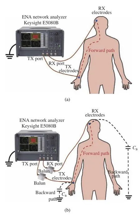
Fig.1 Experimental setup by a VNA:(a) direct measurement with the ground electrodes shorted;(b) a pair of baluns are used to isolate the ground electrodes
In the capacitive BC-WPT,one pair of copper electrodes are adopted for the transmitter and receiver,the diagram and photograph of which are presented in Fig.2.They are implemented in the double layer printed circuit board(PCB) fabricated by 1.6 mm thick FR4,where the signal electrode in contact with the body tissue adopts the bare copper layer without green solder mask and the floating ground electrode refers to the other copper layer with the insulating layer coated.The connection of electrodes to other ports is through the SMA connector.Different sizes and shapes of electrodes may have an impact on the whole channel loss.Therefore,we chose three types of miniaturized electrodes to conduct the contrast experiment: two circular electrodes with diameters of 1 cm (Type B) and 0.8 cm (Type A),one square electrode with a side length of 0.89 cm (Type C).The electrode configurations are shown in Tab.1.In each experiment,the TX and RX electrode types remained the same.
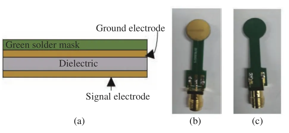
Fig.2 TX and RX electrodes adopted in the experiment:(a)diagram of the signal-ground electrode pair;(b) photograph of the electrode side placed on the tissue;(c)photograph of the electrode side floating in air

Tab.1 Electrode configuration in the experiment
2.2 BC-WPT Prototype System
Although the VNA employs baluns to isolate the two GND electrodes,the indirect return path introduced also limits the accuracy of path loss measurements for wearable devices.In our previous work,we designed a battery powered BCWPT prototype system based on the printed circuit board (PCB),which can eliminate the influence of instrument-based parasitic capacitance coupling to earth ground [19].In this work,the above BC-WPT prototype system is adopted to measure the practical wrist-to-forehead channel characteristics.Fig.3 shows the simplified circuit model,where the power amplifier supplies power with 0 dBm to the TX electrodes at a tunable frequency from 1 MHz to 60 MHz and the power detector measures the signal strength at the TX and RX sides.The dB values of the detected power sent by the transmitter and received at the forehead side are recorded in the laptop through the Bluetooth module of the BCWPT prototype. During the experimental configuration,the TX board and RX board are placed on the table and are connected to the electrodes of TX and RX through the 50 Ωmatched coaxial cable.Except for the measurement device,other experimental conditions,such as the location of electrodes,remain the same as those in the experiment measuring path loss by VNA mentioned above.

Fig.3 Simplified measurement circuit model of the BC-WPT system
3 Measured Results and Analysis
3.1 The Measured Channel Characteristics
As an important part of transmission loss in the whole BC-WPT system with power management circuits,the human body channel loss in the frequency domain of the specific wrist-to-head path is preserved.A previous study proved that the measured results may vary with different test instruments [20].In our work,we adopt two types of measurement devices illustrated in section 2 to compare and study the channel properties.Although a larger electrode size results in lower signal attenuation,electrodes with smaller areas can satisfy the future requirements of miniaturized wearable devices.Therefore,we investigate the effects of electrodes with dimensions kept at a small value.
Fig.4 shows the power loss from 10 MHz to 60 MHz with respect to the three electrodes measured by VNA and the BC-WPT prototype system.From the result,we can observe that the whole trend of path loss versus frequency with respect to different electrodes roughly stays consistent through the same measurement device.During the experimental setup in VNA with baluns,despite a slight decline occurring from 30 MHz to 50 MHz,the three curves continue to rise in general and the best performance is obtained at 60 MHz.For the path loss measured by the BCWPT prototype,the optimum frequency point locates at approximately 30 MHz,bringing a relatively acceptable path loss of–22 dB when adopting electrode type C.All in all,the lowest power loss locates between–22 dB and–33 dB under the six conditions.
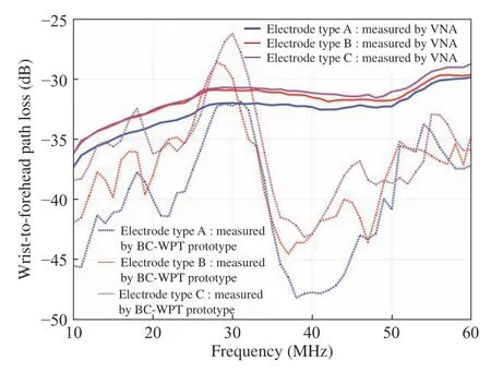
Fig.4 Measured wrist-to-forehead path loss by VNA and the BC-WPT prototype system with respect to the three electrodes displayed in Tab.1
In addition,the effect of electrode type on the channel characteristics mainly lies in the path loss value.Comparing electrode type A and B with the same shape,the result indicates that a larger size can bring a lower path loss.Additionally,the square electrode has a relatively better transmission performance than the circular electrode of the same size The result matches the study about GE shapes in reference[21]. However,it is noted that the difference value is greater when using the BC-WPT prototype system than when using VNA for measurement.This may be due to the fixed parasitic capacitance introduced by baluns dominating the channel properties in the VNA measurement rather than the direct coupling of TX and RX electrodes.
3.2 The Minimum Path Loss Limit
To guide the circuit design to approach the best channel performance,it is necessary to provide the minimum limiting value of path loss in theory.The total channel attenuation is dominated by the backward path loss,mainly due to the small parasitic capacitances coupled by the two GEs and GE-to-external ground.However,the GE coupling effects can be cancelled out completely in theory for passive capacitive properties.There are already several methods in the current study to compensate for GE couplings,such as adding an inductance-capacitance array at the receiver front end to achieve resonance at the operating frequency with backward coupling capacitance [15,22].Here,the GE coupling capacitances can be removed through direct VNA measurements with GEs shorted,where the return path loss is not considered.For the low-impedance forward path going through the specific on-body tissues,the loss remains fixed at a definite frequency.However,for further optimization based on the forward path,we can treat the body as the two-port network collectively to achieve the maximum power sent and received by the two ports through conjugate impedance matching.Overall,the limiting optimization process can be divided into two steps:short the GEs first and then realize conjugate impedance matching at the TX and RX sides.
By directly connecting the two ports of VNA to 1 cm-diameter circular electrodes (electrode type B) placed on the wrist and forehead,the four S-parameters about the forward path are reported in Fig.5.From the S21curve,we can see that the power gain drops initially and rises subsequently as the frequency increases and the peak gain of –21.8 dB occurs at 11 MHz.However,the measured minimum S11and S22parameter values reach–3.56 dB at 60 MHz and–4.15 dB at 32 MHz respectively,both more than –10 dB,which illustrates that in practice,a large portion of energy from the VNA TX port is not fed into the electrodes of TX and that VNA RX port receives only a small amount of energy from the RX electrodes in the sweeping frequency band.Therefore,it is necessary to lower the S11and S22parameters and reduce the port energy reflection,thus improving the channel gain.
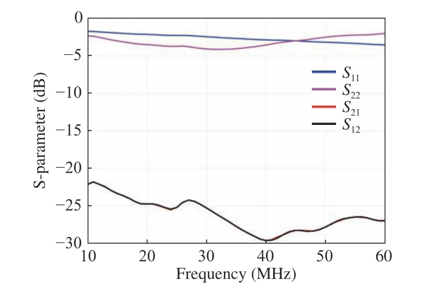
Fig.5 Measured S-parameters by VNA without baluns
Here,we import the recorded S-parameters of two ports into the Advanced Design System(ADS) software to simulate the maximum power gain by performing the conjugate impedance match at two ports.Specifically,the reference impedance of two terminations is set to the conjugate of the input and output impedance of the two-port network loaded with the S-parameter file.The simulation diagram is displayed in Fig.6.In this way,the two-port network always keeps the matching state at every frequency point and we can obtain the minimum limiting loss of the wrist-to-forehead path.

Fig.6 The diagram of simulating the optimal channel loss
Based on the measured S-parameters with the three electrodes in Tab.1,their minimum path loss limit values versus frequency are simulated in the ADS platform.Fig.7 compares the optimal extreme loss after conjugate matching with the original recorded forward path loss from 10 MHz to 60 MHz,which shows that an average channel gain of approximately 7 dB is boosted over the entire frequency band.In addition,comparing the path loss when electrode type C is adopted in Fig.4 with that in Fig.7,the minimum limit value obtained at 11 MHz reaches–13.1 dB,15.6 dB higher than the lowest path loss (–28.7 dB)at 60 MHz through VNA measurement with Baluns,13.1 dB higher than the lowest path loss(–26.2 dB) at 30 MHz measured by the BCWPT prototype.In our simulation at least 10 dB path loss can be compensated in theory,which illustrates that it is possible to boost the transmission performance largely in practice such as performing the conjugate impedance matching at two ports.
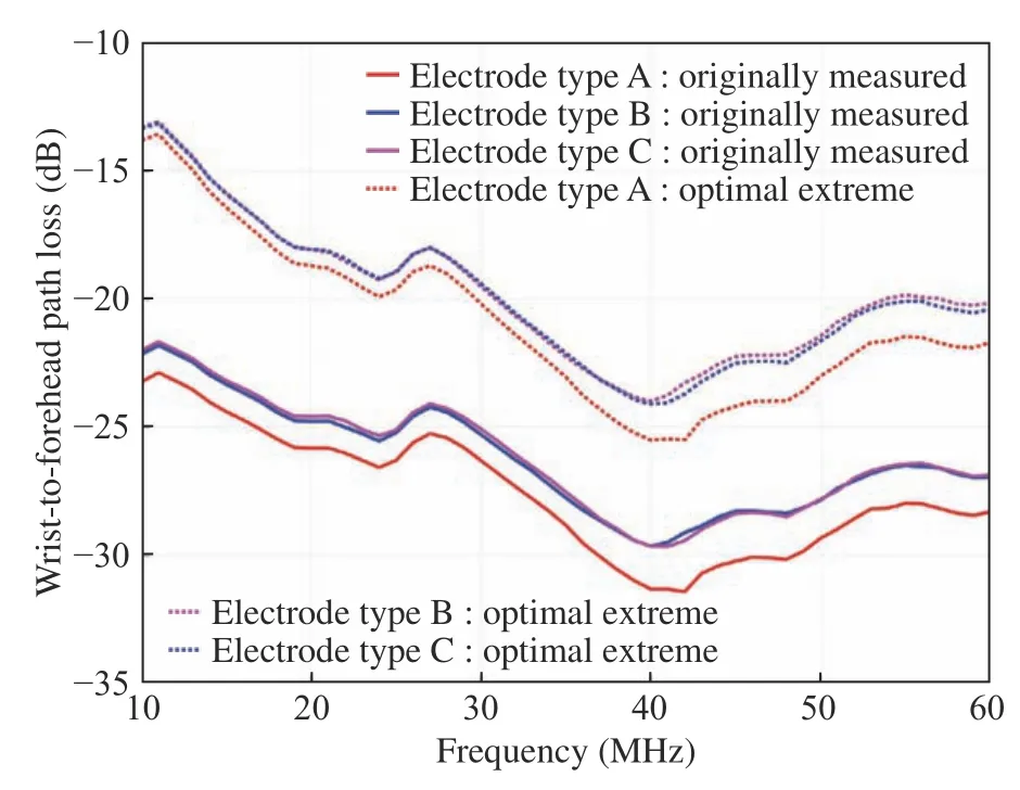
Fig.7 Comparison of optimal extreme and originally measured path loss with three electrodes
4 Measurement of Open-circuit Voltage at Load
4.1 Experiment Setup
The RIGOL DG5102 Arbitrary Waveform Generator with an output impedance of 50 Ω serves as the source device for power delivery in the measurement.A sinusoidal wave is fed into electrodes of TX placed on the left wrist through the SMA connector. The circular RX electrodes placed on the forehead receive the a.c.signal and pass it to the rectifier circuitry implemented on the printed circuit board (PCB).
The rectifying part is composed of four RF diodes (SMS7630-079LF) with the bridge configuration.The reason for choosing this type of diode is that it has a smaller junction capacitance and a forward voltage drop and can achieve a better power conversion efficiency [23].In addition,a capacitor of 1 μF and a resistor of 100 Ω in parallel are used as the rectifier load.A Fluke 15B+digital multimeter is placed in series with the load resistor to measure the open-circuit voltage (OCV) .We recorded the voltage displayed on the multimeter when it remained stable.
Although the source generator is grounded instrument,the multimeter at the load is battery powered,thus not having impact on the return path formed by GEs.The equivalent circuit for measuring the open-circuit voltage obtained at the load based on the BC-WPT system is shown in Fig.8.
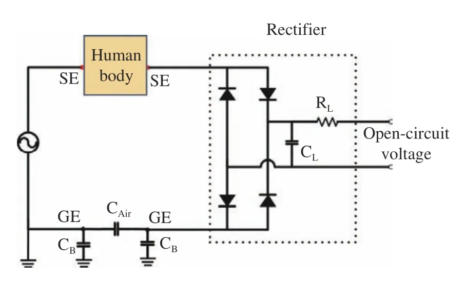
Fig.8 The equivalent circuit for measuring the OCV obtained at the load
4.2 Experiment Results
Different frequencies are measured to show its effect on the open-circuit voltage.In this measurement,the operating frequency is swept from 10 MHz to 60 MHz at 10 MHz per step and the amplitude of the source signal is set to 3Vpp(peak-to-peak voltage).Two 1cm-diameter circular electrodes are adopted here.The measured OCV versus frequency is plotted in Fig.9.Although the channel loss at 10 MHz behaves poorly in Fig.4,the open-circuit voltage obtained at this frequency is relatively high. This may be because that the impedance matching between the output impedance of human body two-port network and the input impedance of the rectifier is better at 10 MHz than some other frequency points.In the frequency band from 20 MHz to 60 MHz,the d.c.voltage continues to rise constantly and reaches a peak of 1.031 V at 60 MHz.The channel loss in Fig.4 does not totally agree with the open-circuit voltage in Fig.9 with respect to frequency,which reminds us that the rectifier and channel effects should be considered as a whole when designing the BC-WPT system in practice to achieve a better performance of recovering wireless power.
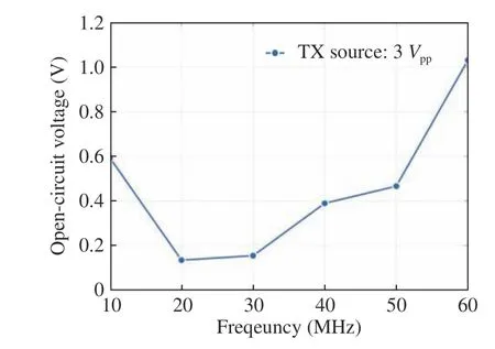
Fig.9 Open-circuit voltage versus frequency
The signal amplitude is changed from 1 Vppto 5 Vppat 1 Vppper step to measure the corresponding d.c.voltage.During this measurement,1cmdiameter circular electrodes are chosen for TX and RX and the transmission frequency is set to be 60 MHz.Fig.10 displays the measured OCV as well as the calculated voltage ratio of the OCV to the source peak-to-peak voltage,the highest value of which are 1.75 V and 35.2 % respectively with 5 VppTX voltage.From the result,it is clear that more open circuit voltage is recovered as the source voltage increases.In addition,calculating the voltage ratio can better reflect the capacity of collecting d.c.voltage from the TX source. The curve indicates that the voltage ratio rises in general as the transmitter outputs higher voltage,which may be due to that the forward voltage of diodes drops lower.
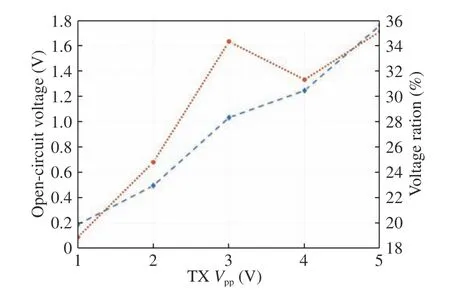
Fig.10 The open-circuit voltage and voltage ratio versus TX Vpp
Tab.2 shows the OCV with respect to the above three different electrodes while the source signal amplitude is adjusted to be 3 Vppand the operating frequency is fixed at 60 MHz.The influence of electrode type on the OCV is consistent with that on the path loss,where electrodes of the same shape of larger size and square electrodes of the same size as the circular electrodes behave better.

Tab.2 Open-circuit voltage with respect to different electrodes
5 Conclusion
We have investigated the wrist-to-forehead channel performance to show the potential of the body channel based wireless power transfer (BCWPT) method to supply power for brain-bioelectronics.In this work,the channel characteristics in the frequency band of 1 MHz–60 MHz with respect to three different miniaturized electrodes are measured by a VNA and a BC-WPT prototype system,where the lowest power loss locates between –22 dB and –33 dB. However,the simulated minimum path loss value can reach nearly –13 dB,which is acceptable in wireless power transmission.In addition,a rectifier is implemented at the receiver side to achieve conversion from a.c.signal to d.c.signal,where the d.c.open-circuit voltage (OCV) is measured. The result shows that the OCV can reach 1.75 V with the transmitter of 50 Ω output impedance supplying 5 Vppsine voltage at 60 MHz when adopting 1 cm-diameter circular electrodes. Overall,the measured results prove the good performance of wirelessly transferring power from the wrist to the forehead based on the BC-WPT method.In our future work,we will establish the whole BCWPT system for powering electronics on the head and further improve the energy conversion efficiency.
杂志排行
Journal of Beijing Institute of Technology的其它文章
- Comparative Study on Galvanic-Coupled Intrabody Channel Characteristic Measurement Methods
- A 2Mbps Human Body Communication Transceiver Based on Body Antenna Effect
- Design of Wireless Power Transfer with High Efficiency for Biomedical Implants
- A Modeling Method of the IBC System Based on the Composite Fading Channel
- A Comparative Study of the Electrodes Gels’Electrical Properties in the Measurement Issues of Intrabody Communication
- A Novel Flexible Antenna at Very High Frequency Band for On-Body Applications
