Monitoring and Prediction of the Vibration Intensity of Seismic Waves Induced in Underwater Rock by Underwater Drilling and Blasting
2022-02-15ZhenxiongWngWeninGuTingLingShoutinZhoPengChenLiufngYu
Zhen-xiong Wng ,Wen-in Gu ,Ting Ling ,Shou-tin Zho ,Peng Chen ,Liu-fng Yu
a Research Institute of Chemical Defence,102205,China
b Army Engineering University,210007,China
c Archives,Department of Space System,100094,China
Keywords:Seismic wave Underwater drilling and blasting Blasting vibration Dimensional analysis Induced seismicity
ABSTRACT All underwater drilling and blasting operations generate seismic waves.However,due to a lack of suitable vibration sensing instruments,most studies on the propagation of seismic waves have been limited to shorelines near construction areas or wharfs,whereas comparatively few studies have been conducted on the larger seafloor itself.To address this gap,a seafloor vibration sensor system was developed and applied in this study that consists of an autonomous acquisition storage terminal,software platform,and hole-plugging device that was designed to record the blasting vibration intensities received through submarine rocks at a given measurement point.Additionally,dimensional analyses were used to derive a predictive equation for the strength of blast vibrations that considered the influence of the water depth.By combining reliable vibration data obtained using the sensor system in submarine rock and the developed predictive equation,it was determined that the water depth was an important factor influencing the measured vibration strength.The results using the newly derived equation were compared to those determined using the Sadowski equation,which is commonly used on land,and it was found that predictions using the derived equation were closer to the experimental values with an average error of less than 10%,representing a significant improvement.Based on these results,the developed sensor system and preliminary theoretical basis was deemed suitable for studying the propagation behavior of submarine seismic waves generated by underwater drilling and blasting operations.
1.Introduction
Blast vibration effects are an important research topic in underwater engineering as there are significant differences between the influences of water,sediments,and water-saturated rocks on the vibrations created by underwater drilling and blasting compared with those created by terrestrial rock borehole blasting.For example,in underwater blasting and drilling operations,explosive energy is transformed into crushing energy in submarine rocks and shockwave energy in water,as well as seismic wave energy [1-3].There are also significant differences in the physical phenomena of the explosions,propagation of seismic waves,and type and degree of damage caused by blasting [4].In underwater blasting,seismic waves can be induced by the direct impact of blasting on the surrounding media,underwater blast-induced shockwaves at the sediment-water interface,and oscillatory impacts of water pulsations on bank slopes.
Advanced instruments used in civilian and military construction techniques have been recently used in many large-scale underwater projects such as subsea tunnels,undersea optical cables,and oil and gas pipelines [5,6].Additionally,it is increasingly common to deploy instruments on the seafloor to monitor underwater conditions to protect the sea and maintain national security.As these projects play critical roles in national economic and defense activities,any damage to such infrastructure by seismic waves can result in significant economic and structural losses.This highlights the need for accurate sensing equipment to monitor vibrations on the seafloor,ensuring the safety and stability of underwater equipment.
The results of extensive engineering and technical studies of underwater blasting have been utilized to develop many effective environmental vibration monitoring techniques and damage assessment methods [7-9].However,owing to the lack of reliable underwater blasting vibration monitoring equipment and sensing techniques,most previous research has focused on monitoring and evaluating damage caused by blast vibrations on shorelines and land-based buildings,and research on the underwater vibrations caused by blasting remains limited [10,11].Previous underwater vibration monitoring research includes works by Araki and Shinohara [12,13],who developed a long-term,high-quality seismic ocean floor borehole observatory system known as“Neath Seafloor Equipment for Recording Earth’s Internal Deformation”(NEREID)to monitor earthquakes on the seafloor and recommended that seismometers be installed in boreholes to reduce the noise caused by infragravity waves [12,13].The NEREID system can be used to obtain ocean data,such as water temperature and ocean current speeds;because the system must be fixed in a given location,its setup is complicated.However,while the NEREID system is useful for monitoring the seismic waves caused by geological movements or volcanic eruptions on the seafloor,it cannot be used to monitor blast-induced vibrations [12-17].
Factors specifically pertaining to underwater drilling and blasting vibrations that should be considered when designing a vibration monitoring system include the dose of detonation,blastcenter distance,difference between the elevations of the measurement points and blasting area,characteristics of the propagation medium,pore network parameters,and influence of water.Indeed,just as the differences in elevation between measurement points and explosion sites on land must be accounted for,differences in the elevations between seafloor measurement points and underwater explosion sites should also be considered.These differences in elevation are particularly important underwater because the water pressure of an explosion differs with the difference in water depth.Accordingly,when explosives are used to break underwater rocks,the distribution of the released energy that generates seismic waves and underwater shock waves will differ between the explosion site and a particular measurement point.Thus,during seismic wave propagation,as the underwater topography changes,the water depth at the measurement points and the seismic wave intensity also change.These gradients must therefore be accounted for when predicting the strength of the induced vibrations as they affect the vibration intensity felt at the seafloor measurement point.
To overcome the limitations of previous studies and address the stated requirements for measurement and prediction of underwater drilling or blasting vibrations,a self-contained underwater blast vibration sensor with a large,reliable data storage capacity was developed and evaluated in this study that is capable of longterm,autonomous acquisition of seismic signals on the seafloor.Key requirements for such a sensor are that it be reliable,convenient,able to guarantee reliable contact with the measured rock surface on the seafloor and meet the stringent design requirement of sealing its mounting hole under specific displacement and stress continuity conditions.In conjunction with the sensor,a software system was developed to oversee the mounting,testing,data transmission,and blast signal processing.Dimensional analysis was then performed to incorporate the water depths at the explosion site and measurement point into a predictive model for obtaining the vibration intensity at a given seafloor measurement point due to a given explosion.The findings of this study will provide a solid foundation for further analyses regarding the propagation behavior of seismic waves on the seafloor induced by underwater drilling and blasting.
2.Materials and methods
2.1.Underwater blast vibration sensor system
There are three main challenges that must be addressed in the design of an underwater blast vibration measurement system.Firstly,it is difficult to place sensors underwater.To overcome this challenge,professional divers must be employed to install sensors at the designated measurement points,and the total number of required dives increases significantly when sensors are deployed in deep water.Secondly,it is difficult to affix vibration sensors to submarine rocks,but to obtain accurate seismic wave signals at a particular measurement point,it is essential that the bottom surface of the sensor be solidly attached to the rock mass to satisfy the requirement for displacement continuity.However,the challenge is that the seafloor is not even and there are no bonding agents available for use with submarine rocks,which makes it virtually impossible to completely secure a sensor to a submarine rock surface.Thirdly,it is difficult to fully waterproof underwater seismic wave sensor systems.Indeed,signals are often transmitted from underwater sensors to land-based data acquisition systems via wired cables because wireless signal transmission underwater is difficult.However,when using signal cables in offshore test operations,it is critical that waterproofing be provided between the sensor and cable and between the cable and test line.If this is not addressed satisfactorily,the tests are likely to fail owing to insufficient waterproofing.
To solve the aforementioned problems and satisfy the functional and performance requirements for a seafloor vibration sensor system,a system was developed that consisted of a self-contained data acquisition and storage system housed inside a holeplugging device as well as an upper-position software platform.The self-contained data acquisition and storage system,shown in Fig.1,included a three-way vibration signal sensor,acceleration integration circuit,signal data acquisition card,data storage system,input/output ports,and power supply control circuits,all of which were mounted in a cylindrical hardened aluminum shell to withstand the conditions in the application environment.
The problem of affixing the sensor to the seafloor rock surface was resolved by fixing the sensor to the bottom of a pre-drilled rock hole using the developed hole-plugging device,shown installed in a submarine rock in Fig.2,which also ensured the motion and force at the contact point between the sensor and the rock body satisfied the continuity requirement.A drilling platform was used to drill the hole in the rock,then the sensor was fed through the sleeve into the hole,pushed into place with the drill pipe,and affixed within the hole using the hole-plugging device.After setting,a wire rope fixed to the sensor was connected to a buoy to assist in the recovery of the sensor.Thus,no divers were required to set and retrieve the sensors.To program the sensor before placement and obtain the data collected from the seafloor after retrieval,the sensor was connected to a laptop computer that executed a program through the data transmission interface(Figs.3 and 4).A control flow chart of the autonomous acquisition storage terminal and the workflow of the host computer software platform are shown in Fig.5.
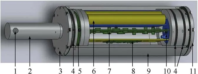
Fig.1. Mechanical structure and component layout of the proposed self-contained blast vibration data acquisition and storage sensor:(1) cable connecting hole;(2)guide rod;(3) hole-plugging device platform;(4) seal ring;(5) interface module;(6)power module;(7)data acquisition board;(8)acceleration integration board;(9)shell;(10) three-way acceleration sensor;and (11) sensor system base.
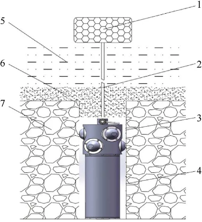
Fig.2. Schematic of the underwater vibration sensor installation:(1)positioning float;(2) cable;(3) hole-plugging device;(4) self-contained vibration data acquisition and storage system;(5) water;(6) rock surface cover;and (7) rock.
2.2.Vibration experiment for underwater drilling and blasting
In this study,seafloor vibration tests were conducted near the underwater drilling and blasting sites associated with the first construction phase of the main channel in the Port of Ningbo-Zhoushan to obtain vibration data from the submarine rock mass under different blasting conditions and test environments.The original rock surface elevation in the construction area was -10-6 m,the rock was moderately weathered tuffaceous sandstone,and the design bottom elevation of the channel was-10.1 m.According to the reef characteristics of this region and those of the drilling and blasting ships,the charging holes were arranged in a rectangular manner;the spacing between the charging holes was 2.5 m,the row spacing of the charging holes was 2.0 m,and the excavation depths of the charging holes were 2-3 m.Further,the diameter of the charge was 90 mm,that of the charging holes was 125 mm,and the number of detonation holes depended on the weather and other factors during construction.Regarding filling of the charging holes for underwater rock blasting,water depths greater than 6 m may not need to be blocked;for water depths greater than 3 m and less than 6 m,the orifice blocking length was 0.5-1.0 m;for water depths less than 3 m,the orifice blocking length was 1.5-2.0 m.Owing to the different construction conditions,the blasting network utilized two types of initiation methods:millisecond initiation and simultaneous initiation.In Table 1,Q is the amount of charge in single-stage blasting.The small amount of initiation charge is the largest charge in single-stage blasting,and at the same time,it is the total charge.The photograph in Fig.6 shows the test site.It was selected based on the water depth and conditions of the submarine rock in the area.The locations of the measuring points should be selected considering the water depth of the setting area and conditions of the underwater rocks.First,the sensors at the measuring points rely on the drilling platform.The platform requires a certain water depth because the platform cannot operate otherwise.In addition,it is necessary to examine the integrity of the underwater rock mass at the measurement points;otherwise,holes cannot be drilled to install the sensors properly.Therefore,the choice of measuring points mainly depends on the underwater rock conditions and water depth during the test and has a certain randomness.The sensors were installed using the drilling platform shown in Fig.7.The workflow of the testing procedure is shown in Fig.8,and the relative positions of the measurement points and explosion site are shown in Fig.9.

Fig.3. Schematic of the overall sensor system.
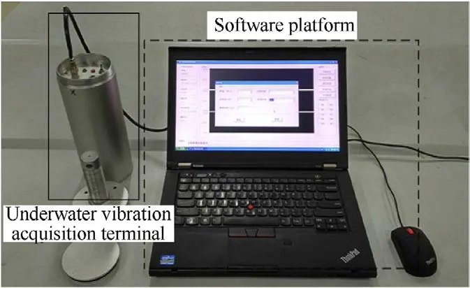
Fig.4. Photograph of the physical sensor system.
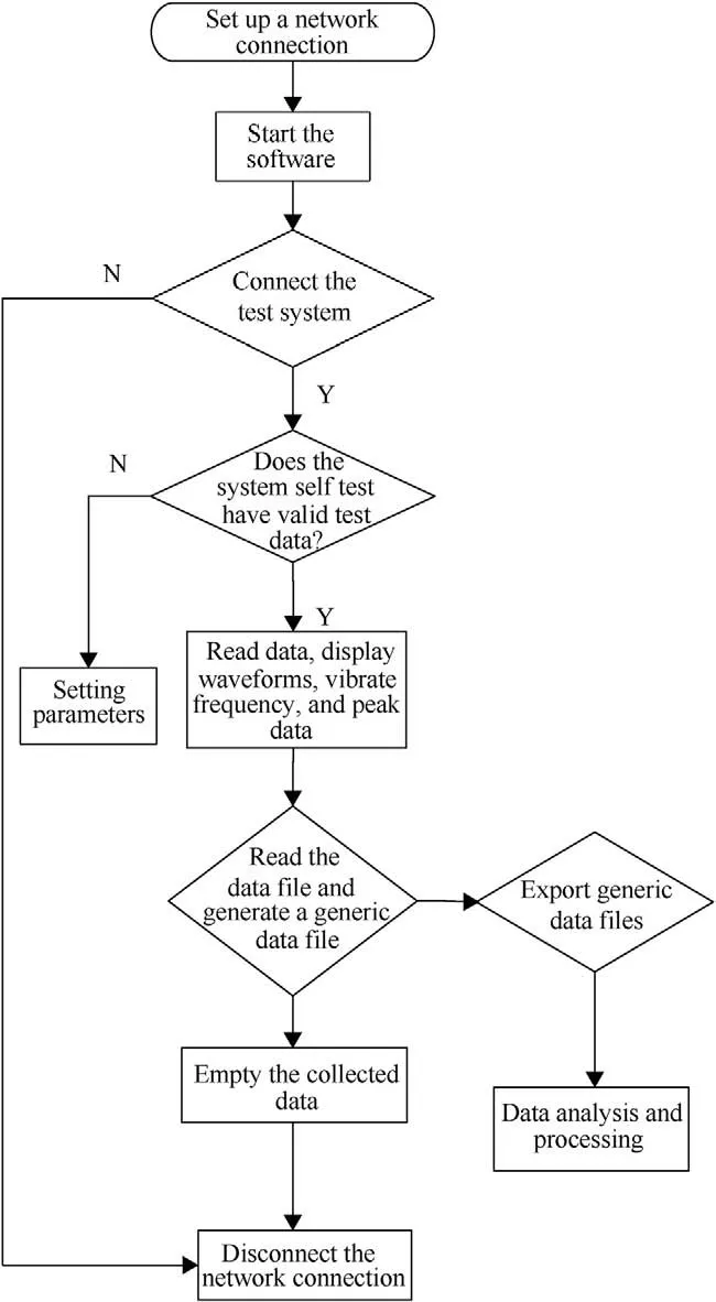
Fig.5. Flow chart of the host computer software platform.
The peak vertical vibration velocity (V) has been widely accepted as an evaluation criterion for vibration prediction in blasting engineering[18].However,a limitation of this approach is that it ignores the effects of blasting in the horizontal and radial directions.Another approach has been to use larger speeds in the horizontal and vertical directions [19,20].However,the understanding of the vibration velocity in a specific direction is limited by these standard methods of measuring vibration intensity,which cannot comprehensively reflect the full intensity in all directions at the measurement point.In contrast,three-directional vibration velocity data can be used to determine the vector combination of vibration intensity (VCV) and can adequately reflect the full variation in the vibrations at the measurement point during blasting.This approach is detailed as follows:
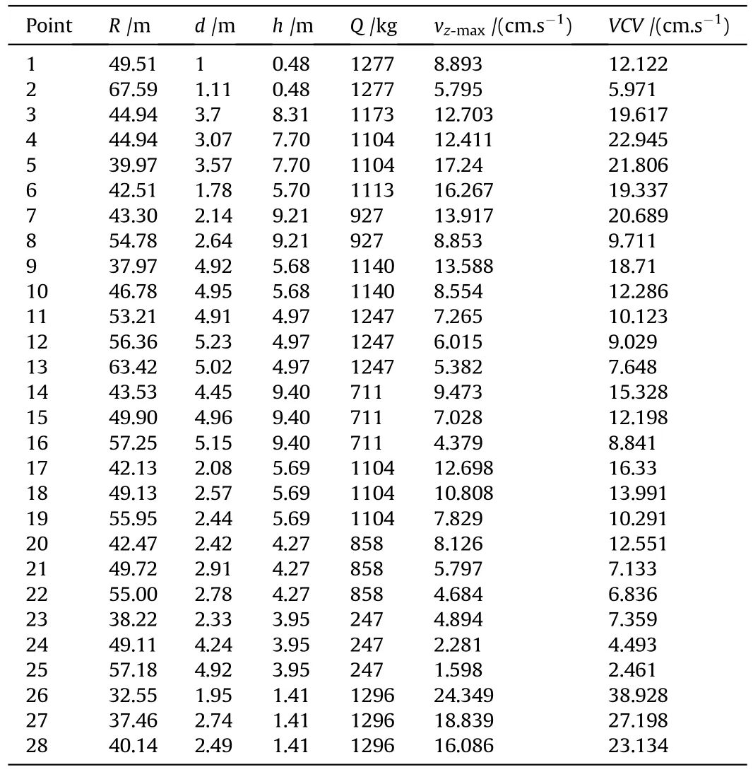
Table 1 Vibration data for underwater measurement points.

where v,v,and vrepresent the respective vibration velocities of the measurement point in the x-,y-,and z-directions at time t.The maximum value of the VCV (VCV) can be considered the peak value of the vibration velocity.The time series of the vertical vibration intensity (V) and VCV at two example measurement points are shown in Fig.10.
The blasting parameters and the vibration velocity data obtained during the tests in this study are given in Table 1.
3.Results and discussion
3.1.Dimensional analysis of vibration strength during underwater drilling and blasting
The effects of the blasting vibrations varied depending on the size of the explosion,conditions of the on-site media(e.g.,lithology,presence of joints,and geological structures),water depth,blasting distance,and differences in elevation.In this study,nine main physical properties were considered when predicting the blastinduced propagation of seismic waves and are detailed in Table 2.
According to π-theory and dimensional analysis techniques,the vibration velocity of a measurement point can be expressed as follows:

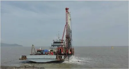
Fig.6. Underwater vibration sensor installation and testing site.

Fig.7. Photographs of the underwater vibration test sensor installation.
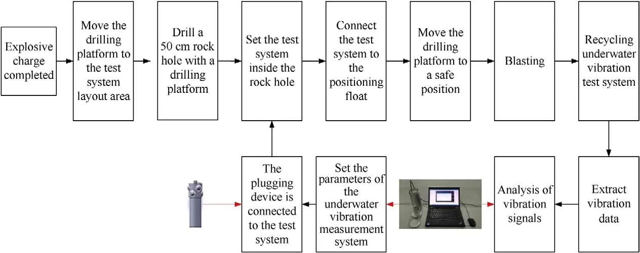
Fig.8. Workflow of the experimental procedure.
where Q is the total detonation dose,E is the total explosive energy,R is the distance from the center of the explosion site to the measurement point,c is the seismic wave velocity,ρ is the density of the submarine rocks at the measurement point,d is the water depth at the measurement point,h is the water depth at the explosion site,and t is time.The underwater blasting vibration speed was related to the nine physical quantities defined in Table 2,among which Q,R,and c are independent variables and π signifies a dimensionless quantity.
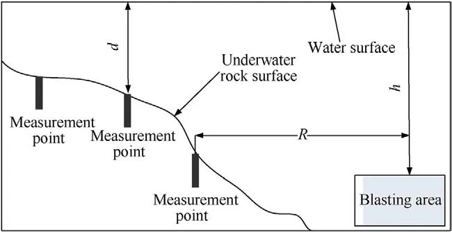
Fig.9. Schematic of the relative positions of the measurement points and the explosion site (blasting area).

where x,x,and xare all undetermined coefficients.According to dimensional homogeneity,

where v is the dimensional vibration velocity at the measurement point,which is equivalent to the multiplied units of measure shown in Table 2.Thus,when x=0,x=0,and x=1,

By analogy,the remaining physical properties can be expressed as follows:

Note that the water depth must be considered for predicting vibration intensity as it is an important factor in the effects of underwater drilling and blasting[21].As the products and involutions of different dimensionless quantities are still dimensionless[22,23],the dimensionless quantity πcan be obtained by combining π,π,and π:
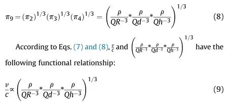
As the rock density ρ and seismic wave velocity c can be considered constants under the same test site conditions,the logarithm for both sides of Eq.(9) can be obtained as follows:
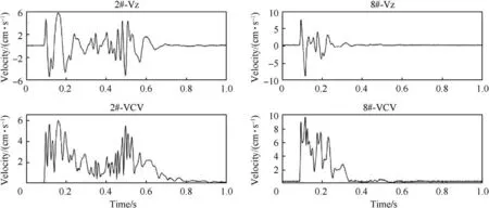
Fig.10. Time series of the vertical vibration intensity (Vz) and the vector combination of the vibration intensity (VCV) at measurement points #2 and #8.

Table 2 Main physical properties involved in blast-induced seismicity.
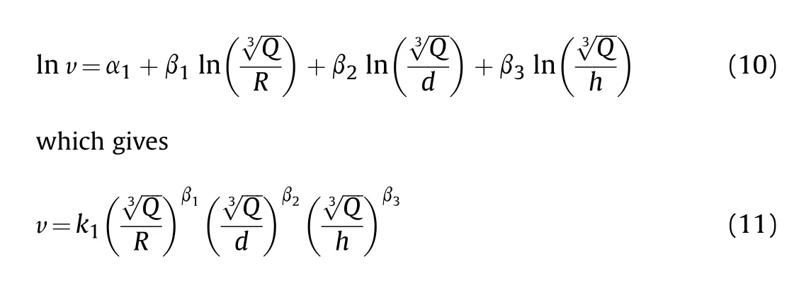
where k is the comprehensive coefficient of influence for the given site and blasting parameters,and β,β,and βare the attenuation coefficients of the distance from the center of the explosion site,water depth at the measurement point,and water depth at the explosion site,respectively.When the influence of water depth is not considered,the predictive equation for the vibration intensity is

Eq.(12) is consistent with the form used in Sadowski’s study[24] of blasting vibration intensities on land.
3.2.Prediction of vibration intensity by fitting
Eq.(12)is the predictive equation for determining the vibration intensity adopted on land.According to the data given in Table 1,The 7th,14th,21st and 28th data were selected as the vibration data of the test prediction,and the rest data were used as the basic data of formula fitting.Based on the above data analysis,the equation for calculating the predicted vibration intensity through the submarine rocks at the measurement point without considering the influence of water depth can be obtained as follows:

However,as research into the effects of vibration hazards has continued,the difference in elevation between the blasting area and measurement point has been gradually introduced into the predictive equations of vibration intensity on land,considerably improving the accuracy of such predictions [25-30].As discussed previously,drilling and blasting operations are more complicated underwater than on dry land as there are more factors that influence the intensity of blast-induced vibrations,the most notable of which is the presence of water.Using dimensional analysis,the water depths at the measurement point and explosion site in this study as per Eq.(11)and the vibration data in Table 1 were fitted to obtain the following:

The fitting index of Eq.(14)shows that the absolute value of the coefficient of influence for the water depth at the explosion site was greater than that at the measurement point.Except for a slightly larger value at the measurement point where Vwas recorded,the coefficients of influence for the water depth at the measurement points in Eqs.(13) and (14) were smaller than those at the explosion site.If only the influence of depth of water at the explosion site on the vibration intensity is considered,Eq.(11)can be simplified as

Using the test data reported in Table 1,the following predictive equations were obtained based on Eq.(15) by fitting using the regress function in Matlab:

The significance level was set to 0.05 [31],and the correlation coefficients and F values were obtained as shown in Table 3.Table 3 indicates that the correlation coefficients of fitted Eqs.(14)and(16)considering the influence of water depth are considerably improved compared to those of Eq(13),which indicates that waterdepth considerably influences the vibration intensity.

Table 3 Correlation coefficients and F-statistics of Eqs.(13),(14) and(16).
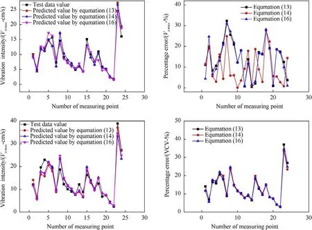
Fig.11. Comparisons of the(a)predicted and experimental values obtained by different fitting equations for VZ-max,(b)errors obtained by different fitting equations for VZ-max,(c)predicted and experimental values obtained by different fitting equations for VCVmax,and (d) errors obtained by different fitting equations for VCVmax,in which VCVmax is the maximum vector combination of vibration intensity and VZ-max is the maximum vertical vibration intensity.
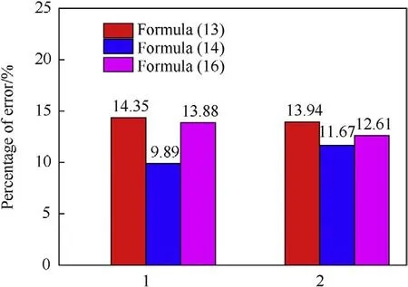
Fig.12. Comparison of the prediction errors obtained using different fitting equations.
A comparison of the experimental and predicted values obtained using the different fitting equations and their calculated error values is shown in Fig.11(a-d);the values obtained by fitting the predictive equation based on the water depth were closer to the experimental values,indicating that the prediction accuracy considerably improved compared to the other equations.Comparing the prediction errors of different fitting equations indicated that the deviation of the results without considering the influence of water depth(Eq.(13))was large and the range of error was wide (Fig.11).
When Vwas used as the vibration intensity index,the prediction accuracy of the equation that considered the influence of water depth improved(Fig.12).The prediction accuracy of Eq.(16)when only the water depth effect of the explosion site was considered was 13.88%.However,when the water depths at both the explosion site and the measurement point were considered,theprediction accuracy of Eq.(14) was 9.89% and the error range was narrow,indicating that it predicted the vibration intensity better than the other equations.When VCV was used as the vibration intensity index,the error that considered the influence of the water depth(Eq.(14)) was 11.67%.

Table 4 Vibration data for underwater measurement points.(cm/s).
The vibration data of No.7,No.14,No.21 and No.28 are predicted by using the fitting formula.The prediction data and prediction error of different formulas are shown in Table 4.Eq.(14)has the best prediction precision,especially when Vis predicted,the prediction error of Eq.(14)is less than 15%,the average error is 12.57%.Similarly,the prediction of VCV in the above four data shows that,although the overall prediction error is larger than the prediction error of V,the average error of Eq.(14)is still the most accurate among the three prediction methods.The results of this study demonstrate that the influence of the water depth on the vibration intensity cannot be ignored in the prediction of seismic behaviors resulting from underwater drilling and blasting operations.This is emphasized by the fact that the equations including the influence of the water depth exhibited significantly higher prediction accuracy.When different vibration intensity indicators were selected,the accuracy of the predicted vibration intensities differed.Overall,Eq.(14),which included the water depths at both the measurement point and the explosion site,exhibited the highest prediction accuracy.
4.Conclusions
In this study,a novel underwater blast vibration sensor consisting of self-contained data acquisition and storage system housed inside a hole-plugging device as well as a surface-based software platform was developed to collect and analyze the vibrations of submarine rocks exposed to drilling and blasting operations.Additionally,the factors affecting the vibration intensity of such rocks were analyzed via dimensional theory.We found that the proposed underwater vibration sensor system was able to collect the vibrational velocities at the rock measurement point under complex seafloor conditions.The obtained data were reliable and suitable for use in research on the seismic wave propagation behavior of submarine rocks.
Equations for predicting the vibration intensity during underwater drilling and blasting operations while accounting for the water depth were obtained via dimensional analysis.The water depth was an important factor affecting the vibration intensities experienced by submarine rocks during underwater drilling and blasting by fitting the experimentally obtained vibration data.On this basis,a reliable equation was proposed for predicting the vibration intensity induced by underwater blasting that incorporates the blasting distance,amount of charge,and water depth at the blasting area and measurement point as variables.The vibration intensity of submarine rocks was then predicted using several different fitting equations,and the equation that considered the influence of the water depth at both the explosion site and the measurement point was shown to most accurately predict the vibration intensity.
This work was supported by the National Key R&D Program Project Fund[2017YFC0209901]and the National Defense Program[BY209J033].
The authors declare that they have no known competing financial interests or personal relationships that could have appeared to influence the work reported in this paper.
We would like to thank the Xiangshan Project Department of the Qingdao Coastal Defense Bureau for providing an excellent test site,and especially Su Bo,who provided valuable engineering assistance in the test arrangement and operation over the course of the test.We also thank Liu Jianqing,Xu Jinglin,Dr.Chen Jianghai,Xu Haoming,Lu Ming,Liu Xin,and their team for their assistance in this study,and especially Dr.Chen Jianghai for his invaluable assistance during the testing.
杂志排行
Defence Technology的其它文章
- Defence Technology
- A study on the surface overpressure distribution and formation of a double curvature liner under a two-point initiation
- Performances and direct writing of CL-20 based ultraviolet curing explosive ink
- One-step synthesis of FeO(OH) nanoparticles by electric explosion of iron wire underwater
- Driving force coordinated control of an 8×8 in-wheel motor drive vehicle with tire-road friction coefficient identification
- Effects of Mg/PTFE pyrotechnic compositions on reignition characteristics of base bleed propellants and heating mechanism
