Design and experimental study of active balancing actuator driven by ultrasonic motor①
2022-02-11WANGYangyang王洋洋PANXinGAOJinjiWUHaiqi
WANG Yangyang(王洋洋),PAN Xin②,GAO Jinji,WU Haiqi
(*Beijing Key Laboratory of Health Monitoring and Self-recovery for High-end Mechanical Equipment,Beijing University of Chemical Technology,Beijing 100029,P.R.China)
(**Key Laboratory of Engine Health Monitoring-Control and Networking of Ministry of Education,Beijing University of Chemical Technology,Beijing 100029,P.R.China)
Abstract
Key words:active balancing,unbalance vibration control,ultrasonic motor
0 Introduction
In modern industry,mechanical vibration is a major obstacle to the development of rotating machinery.Excessive vibration caused by rotor imbalance is one of the most common faults of rotating machinery,which seriously affects the operation efficiency,working accuracy and service life of equipment[1].The active balancing actuator can actively reduce the unbalance vibration during operation without shutdown and manual intervention,and the balancing speed is fast,which is considered to be an effective method to solve the unbalance vibration of rotating machinery.At present,it has achieved good engineering application in high-end machine tools and aero-engine[2-4].The active balancing system is mainly composed of sensors(detecting rotating speed and vibration amplitude of rotating equipment),controllers(signal processing and output),balancing actuator(reducing vibration amplitude of equipment)and related accessories.As the final actuator of the whole system,the balancing actuator has always been the key research object in this field in China and abroad[5].According to the different ways of changing the rotor mass distribution inside the actuator,the active online balancing actuator can be divided into three types:motor type[6],liquid type[7-9]and electromagnetic type[10-12].
The motor type active balancing actuator has the advantages of easy installation,no complex auxiliary device,simple operation,fast balancing speed and high balancing accuracy.The rotor can be balanced online by reducing or increasing the correction quality in the appropriate position of the rotor in operation.At present,the main motor-type active balancing actuators on the market are mostly driven by complex mechanical structures to reach the designated position to suppress the unbalance vibration of the equipment.Although this method can achieve the effect of vibration suppression,due to the meshing of complex gears and worms,the whole device is complex,difficult to manufacture and assemble,and difficult to maintain in the later stage[13-14].Therefore,this paper introduces a new type of active balancing actuator driven by ultrasonic motor,which effectively avoids the mechanical transmission chain such as gear and worm,greatly reduces the difficulty of manufacturing and assembly,and verifies its feasibility through experiments.
1 Fundamental principle
The active balancing actuator studied in this paper is the balancing mode of double counterweights balancing,and its principle is shown in Fig.1.The vibration sensor(acceleration sensor)is used to collect the vibration amplitude of the rotating equipment,and the positioning sensor is used to determine the position of the counterweight;key-phase sensor is used to collect rotational speed information of rotating equipment.

Fig.1 Balance principle of double counterweights
The collected signals are processed by the National Instruments(NI)board and passed to the controller,personal computer(PC)terminal,and then the instructions are sent to the ultrasonic motor inside the active balancing actuator.To suppress the unbalance vibration of rotating equipment,the ultrasonic motor is used to drive the counterweight to the designated position after calculation.
This article introduces a new type of active balancing actuator based on ultrasonic motor drive.The ultrasonic motor uses the inverse piezoelectric effect of the internal piezoelectric material to stimulate the micro vibration of the elastomer in the ultrasonic frequency band,and converts the friction between the stator and the rotor into the rotation of the rotor[15].Therefore,the new type of active balancing actuator studied in this paper uses the above-mentioned working characteristics of the ultrasonic motor to realize the self-locking and driving of the counterweight.The specific working principle is as follows.When the mass distribution of the counterweight needs to be adjusted,the ultrasonic motor is powered,and the frictional force generated by the piezoelectric ceramic vibration in the ultrasonic motor drives the counterweight to rotate step by step to form the compensation quality required to suppress the unbalance vibration of the equipment;when the counterweight reaches the specified position,the power supply for the ultrasonic motor is stopped,and the stable self-locking of the counterweight position is realized through the friction torque generated between the stator and the rotor of the ultrasonic motor.The whole actuator has a simple structure and is easy to assemble and maintain.At the same time,the entire actuator uses infrared signals to receive instructions to control the internal ultrasonic motor to drive the special-shaped counterweight to reach the specified position and the combined compensation quality.Its structure is shown in Fig.2.
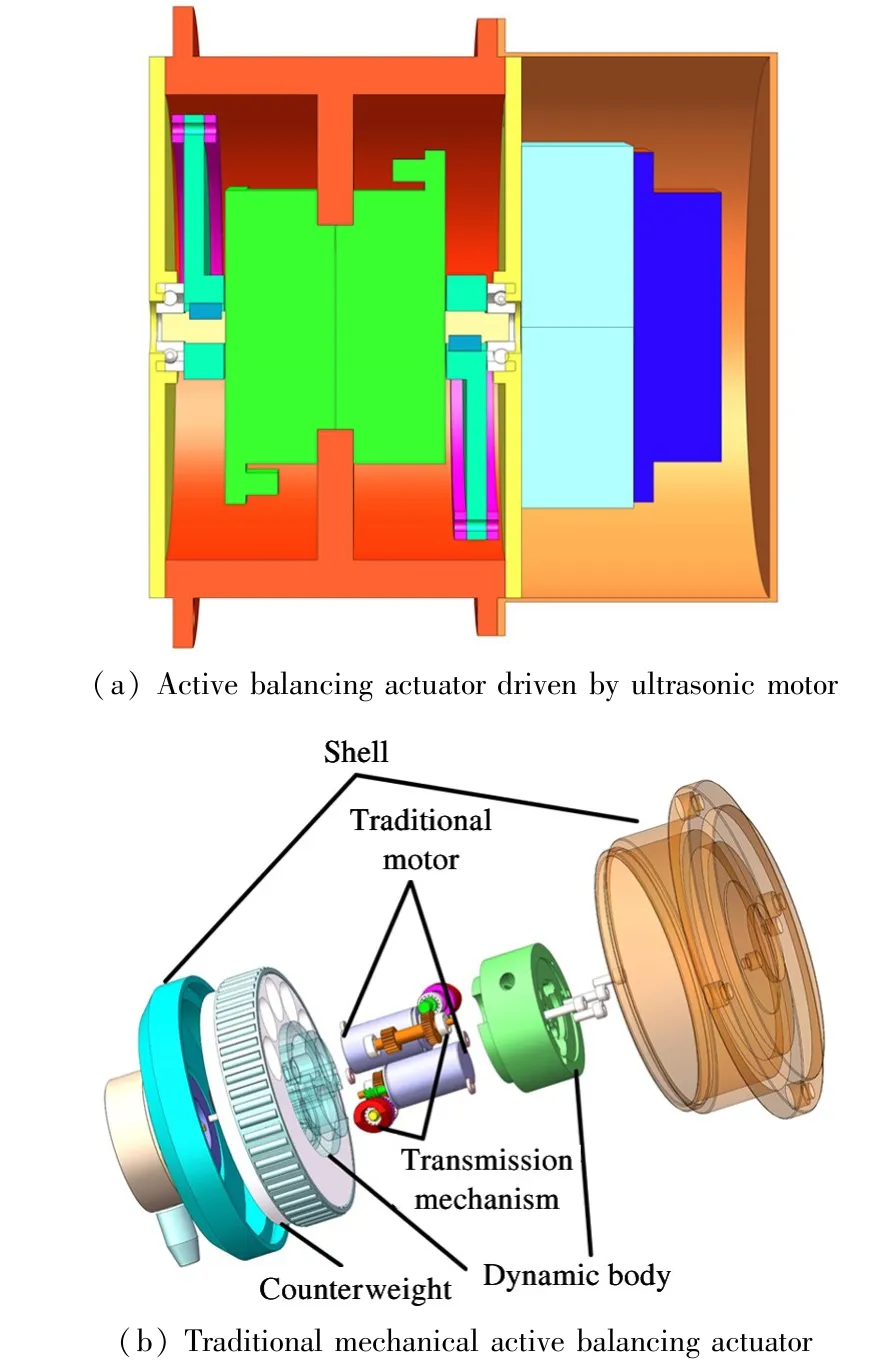
Fig.2 Structure diagram of active balancing actuator
Therefore,compared with the traditional motortype balancing actuator,the active balancing actuator based on ultrasonic motor drive studied in this paper has the following advantages.
(1)With compact structure and large torque density(torque mass ratio),the torque mass ratio of the ultrasonic motor can reach 5-10 times that of the traditional electromagnetic motor,which helps to reduce the axial size of the actuator[15].
(2)With low speed and large torque,direct drive can be realized without gear reduction mechanism.The structure is simple and easy to maintain in the later stage.
(3)The inertia of motor moving parts is small,which can achieve millisecond response speed.The position and velocity control precision is high,and the displacement resolution is high.The whole actuator can control the counterweight accurately to suppress the vibration of the equipment.
(4)The motor can be power-off self-locking,and has a large holding torque,so that the entire actuator does not need to use the worm structure to achieve selflocking.
(5)No magnetic field is produced and is not disturbed by external magnetic field.Taking into account the working environment of the actuator,when the piezoelectric material and friction material of the ultrasonic motor are properly selected,it can work in extreme environments such as vacuum,high/low temperature environment,which greatly improves the application range of the actuator.
2 Structure design
2.1 Design of actuator structure
Active balancing actuator is mainly composed of ultrasonic motor and special-shaped counterweight,in which the whole actuator rotates synchronously with the rotating equipment.The whole active balancing actuator is shown in Fig.3.The whole device is arranged symmetrically with the shell ribs,so as not to affect the balance quality of the balance rotor itself.Two symmetrical ultrasonic motors are fixed on the shell rib plate[16].When the ultrasonic motor receives the signal of the controller,the mass distribution inside the whole device is changed by controlling the position of the special-shaped counterweight,in order to suppress unbalance vibration of rotor on line.The special-shaped counterweight with the motor is made of brass,and the counterweight part with the shaft is strengthened.In order to make full use of the internal space of the actuator and improve the maximum quality of the balance,the whole counterweight is designed as a specialshaped structure.At the same time,the protruding part is connected to the main body through the sinker screw,which can be determined by the unbalance vibration value of the rotating equipment.
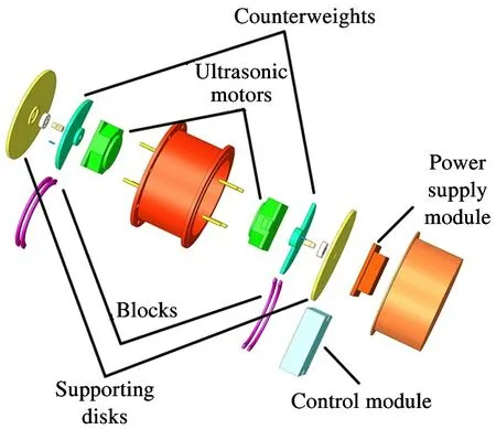
Fig.3 Explosion diagram of active balancing actuator
Whether the protruding part is installed or not can reduce the quality of the whole actuator.On the outside of the special-shaped counterweight,there are two supporting plates matching the shaft through the bearing.The supporting plate is made of aluminum alloy,so as to reduce the quality of the whole actuator.One side of the support plate is embedded in the flange plate of the grinder to protect the internal structure.The other side of the support plate is used as the installation deck of the ultrasonic motor controller,and also plays a protective role.
2.2 Balance ability
The balance ability of the whole actuator depends on the structure and size of the counterweight.In this paper,the active balancing actuator based on ultrasonic motor is studied.In order to shorten the axial size and maximize the balance ability of the whole actuator,the counterweight is designed as a semi disc and a convex part.The two parts are connected by sink screw,as shown in Fig.4.On the one hand to increase the balance ability of the entire actuator.On the other hand,when the required compensation mass is too small,the mass of the entire actuator can be reduced,and the influence on the spindle of the rotating equipment can be reduced.At the same time,the shaft hole with the motor shaft is strengthened,so that the structural strength of the whole counterweight is improved and the balance ability is guaranteed.
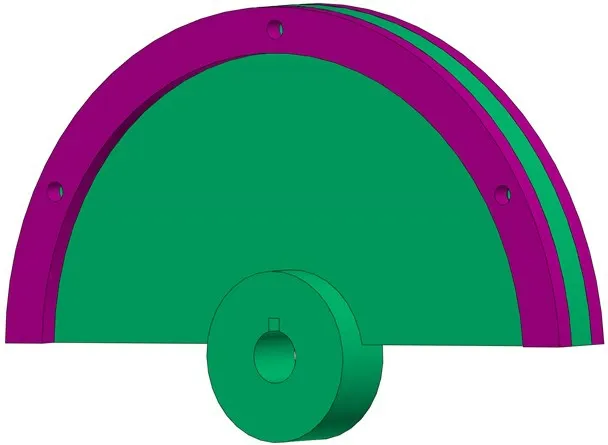
Fig.4 Diagram of active balancing actuator counterweight and blocks
It can be seen from Fig.5 that the initial unbalance mass of the rotor of the balancing rotating equipment isU0.When the actuator accepts the instruction,the two disks begin to rotate gradually driven by the ultrasonic motor,so as to change the angle between the massUAandUBof the counterweights on both sides.According to the parallelogram rule,the total compensation massUCof active balancing actuator increases with the decrease of angleφ.When the orientation of counterweights on both sides is the same and the angle is 0°,the total equilibrium massUCreaches the maximum,namely the sum ofUAandUB.By changing the anglesφandφC,the equilibrium mass of the entire active balancing actuator increases from 0 to the maximum value ofUC.Therefore,the maximum value ofUCis the balance ability of the actuator[2].

Fig.5 Balance principle diagram of double counterweights
The balance ability of the counterweight can be expressed as

Among them,the overall material of the counterweight is brass alloy,and the densityρis 0.0085 g/mm3.The overall size of the counterweight is shown in Table 1.With Eq.(1)and Eq.(2),the balance ability of the whole actuator can be calculated to be 13 443.2 g·mm.
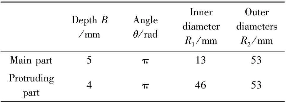
Table 1 Counterweight design
3 Structural simulation of key parts
According to the real working environment of the active balancing actuator studied in this paper,the key parts of the actuator(motor shaft,shaft key and counterweight)were simulated by ANSYS finite element analysis software.Under the working condition of 1000 r/min,the actuator rotates with the grinder and drives the counterweight at the same time.The stress concentration is analyzed.It is concluded that the structure of the active balancing actuator driven by ultrasonic motor is stable and the stress does not exceed the yield limit of the material.It provides theoretical support for the following experimental verification.
Firstly,AutoCAD software is used to obtain the size of the key parts of the actuator.Secondly,Solid-Works software is used to establish three-dimensional model.Then,the model was imported into ANSYS Workbench software to simplify the screw hole and the protruding part of the counterweight that did not affect the structural stress change,and the whole counterweight was combined into a whole part.After simplification,the material properties of the whole part of the assembly are defined.The counterweights and the motor shaft are brass alloy and the flat key is 45 steel.Meshing,determines the boundary conditions and applied load,and finally solves the stress of the model,as shown in Fig.6.
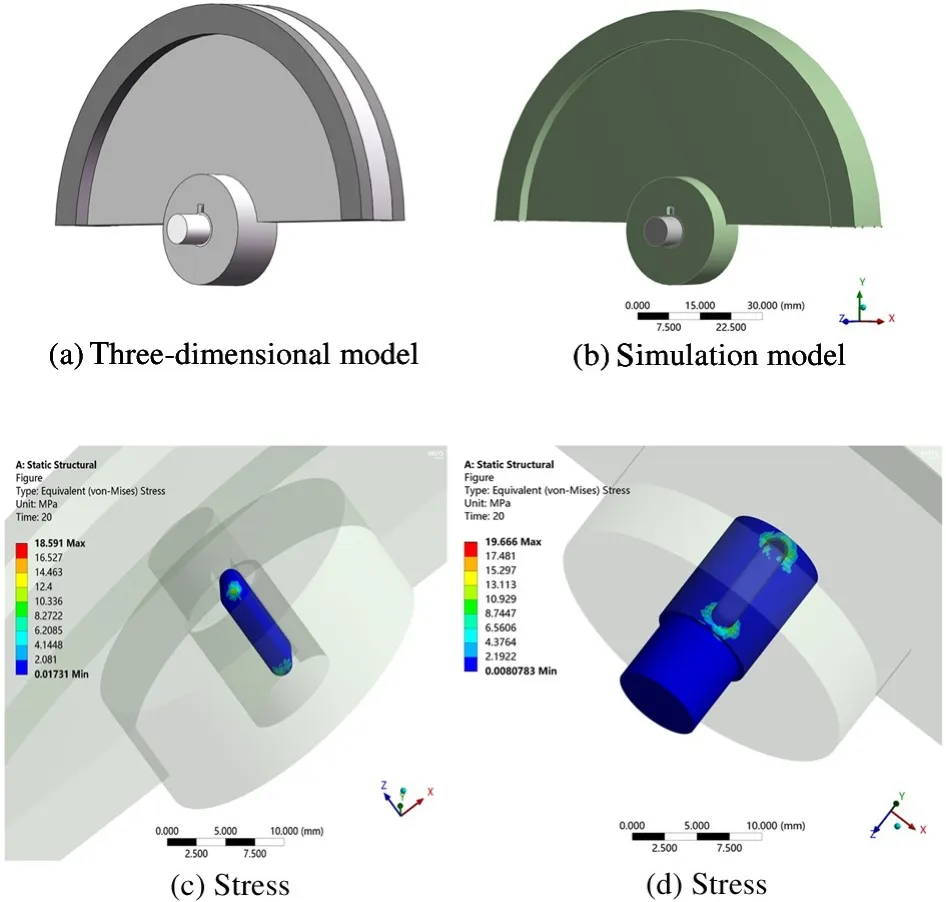
Fig.6 Three-dimensional simulation of key structures
In order to determine the effect of motor shaft diameter on the structure of the key parts of the actuator,the relationship between the diameter of the motor shaft and the maximum stress of the key was simulated by ANSYS Workbench software at the speed of 1000 r/min.The simulation result is shown in Fig.7.
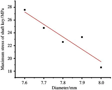
Fig.7 Linear fitting diagram of diameter and maximum stress of shaft key
From the fitting results of three-dimensional simulation,it can be seen that with the increase of shaft diameter,the maximum stress of the key is reduced accordingly,and the stress of shaft key is far less than the yield limit of the material.At the rotational speed of 1000 r/min,the whole actuator can achieve structural stability.
4 Experimental verification
To verify the feasibility of active actuator driven by ultrasonic motor,the actuator is processed,assembled and tested.The maximum diameter of the whole actuator is 150 mm.The balance ability of the counterweight can reach above 13 000 g·mm.
In order to verify the effectiveness of the above active balancing system,a relevant experimental platform is built for experimental verification.The experimental platform takes the grinder spindle as the object,and the balancing actuator is installed at one end of the spindle.
The acceleration sensor is used to monitor the vibration of the grinder system online,and the photoelectric sensor is used to feedback the speed information of the grinder spindle in real time.The data acquisition unit of NI is a cDAQ data acquisition device that contains two data acquisition modules and a digital output module.The two data acquisition modules are used to collect the vibration signal and speed signal measured by the grinder,and the digital output module is used to output the control instructions from the PC side,the whole experimental device is shown in Fig.8.The vibration signal of grinding machine spindle system is analyzed online by personal computer as control unit,and the initial unbalance of grinding machine spindle system is calculated by program.The entire actuator is shown in Fig.9,which is powered by 12V DC rechargeable battery.The control module receives the infrared signal of the remote control circuit board,and transmits the signal to the ultrasonic motor at the same time,driving the counterweight to step at a certain angle.
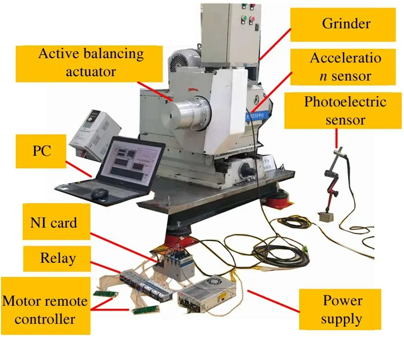
Fig.8 Overall diagram of experimental device

Fig.9 Active balancing actuator diagram
One side of the whole actuator close to the grinder flange is the counterweightA,and the corresponding other side is named as sideB.The speed of the active balancing experiment is 1000 r/min to verify whether the active balancing actuator driven by ultrasonic motor is safe and stable to suppress the unbalance vibration.TheBside plate is fixed and theAside plate is rotated for one week to obtain the vibration amplitude variation curve of the actuator counterweight after rotation for a whole week,as shown in Fig.10.
It can be seen from the experimental results in the following figure that the vibration amplitude of the whole grinder test bench reaches the maximum value of 11.3μm after the initial 2.4μm is rotated by the counterweight for half a week.When the counterweight rotates over the position of the maximum vibration,the vibration amplitude is gradually reduced to 1.8μm.From Fig.10(b),it can be concluded that the vibration amplitude of the outer counterweight is larger than that of the inner plate during the whole rotation cycle,gradually decreasing from the initial 22μm to 4μm,and gradually increasing from the minimum value to 23μm.The vibration amplitude difference between sideAandBis mainly caused by the axial distance between two counterweight plates,which will be reduced as much as possible during the next research plan.
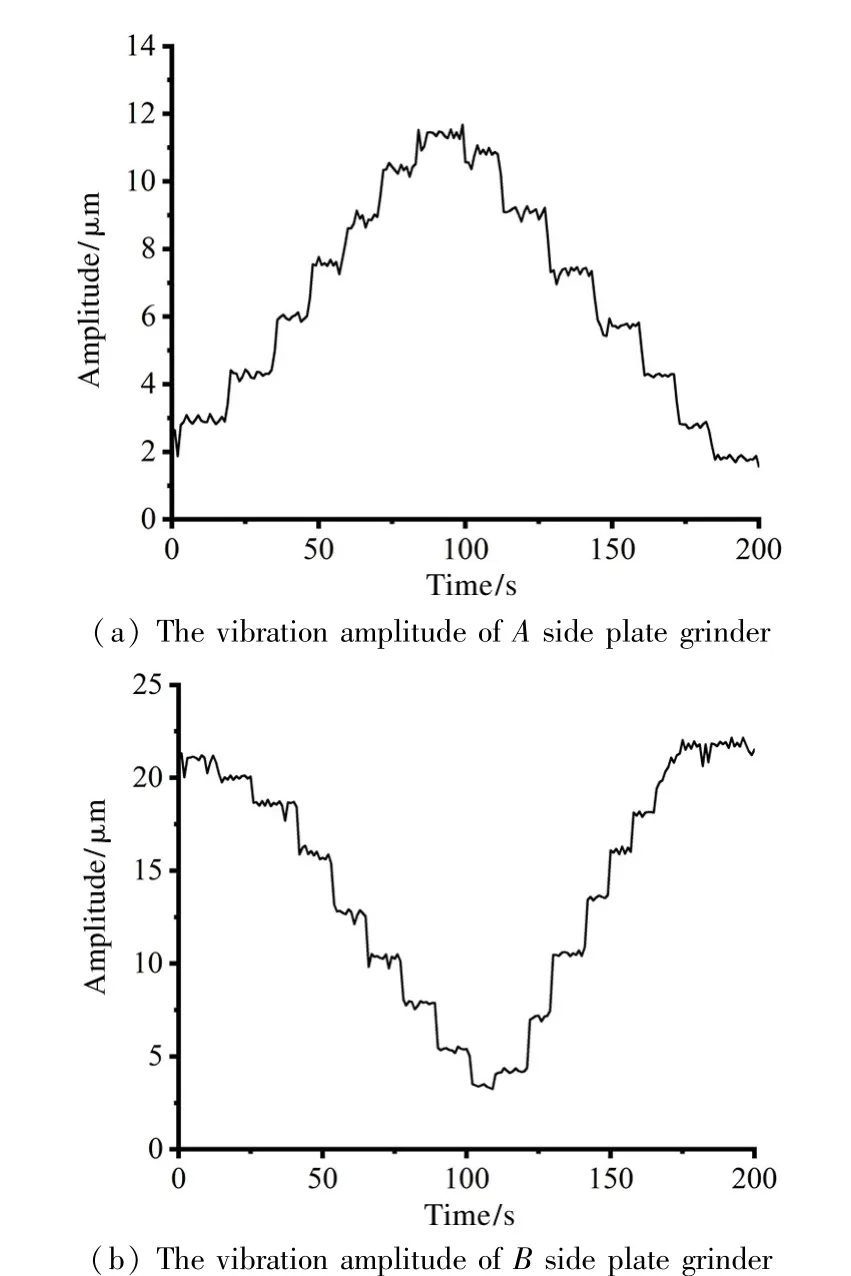
Fig.10 Vibration amplitude diagram of grinder
It can be seen that after the plates on both sides ofAandBare rotated for a whole week,the vibration amplitude of the grinder test bench can be effectively controlled,and the new active balancing actuator based on ultrasonic motor has no misstep phenomenon in adjusting the whole week movement of the counterweights on both sides.
5 Conclusions
A new active balancing actuator structure driven by ultrasonic motor is proposed.The working principle and basic structure of the actuator are introduced.The structure simulation of the key components of the actuator is carried out by ANSYS software.The feasibility and effectiveness of the new structure are verified by the test experiment of the grinding machine test bench.The conclusions are as follows.
(1)The principle of the new balancing method driven by ultrasonic motor is feasible.The designed structure has the advantages of no complex transmission mechanism,simple structure and fast response.
(2)The designed new balancing actuator can change its mass distribution in real time according to the control instructions under rotating conditions,and its working performance is stable.Moreover,the unbalance vibration amplitude can be effectively controlled from 11.3μm to 1.8μm on the grinder test bench.
In the subsequent research,it is proposed to further optimize the structure of this kind of actuator,improve the dynamic performance of the actuator,and apply it to more high-end equipment,so as to provide technical support for the engineering application of this kind of balancing actuator.
猜你喜欢
杂志排行
High Technology Letters的其它文章
- Research on buffer structure and flow field simulation of swash plate plunger type hydraulic transformer①
- Effect of integral squeeze film damper on vibration and noise of spur gear with center-distance error①
- Workspace optimization of parallel robot by using multi-objective genetic algorithm①
- Design and implementation of gasifier flame detection system based on SCNN①
- A simplified hardware-friendly contour prediction algorithm in 3D-HEVC and parallelization design①
- An efficient cross-layer buffer management optimization scheme for 5G protocol stack①
