An efficient cross-layer buffer management optimization scheme for 5G protocol stack①
2022-02-11YANGXining杨喜宁ZHOUYiqingCHENYang
YANG Xining(杨喜宁),ZHOU Yiqing②*,CHEN Yang
(*Institute of Computing Technology,Chinese Academy of Sciences,Beijing 100083,P.R.China)
(**School of Computer Science and Technology,University of Chinese Academy of Science,Beijing 100190,P.R.China)
Abstract
Key words:cross-layer optimization,5G protocol stack,evaluation framework,OpenAirInterface(OAI)
0 Introduction
With the rapid development and wide application of mobile communications[1-3],more challenging requirements,characterized by higher end-user data rates and massive device connections and high reliability critical communication,are emerging[4-6].To meet these requirements 3GPP initiated the development of a new radio-access technology known as NR around 2012 and announced the freezing of the R16 standard in July,2020,which defined performance metrics for ultralow latency and highly reliable communication(uRLLC)supporting 1 ms UP latency with 99.999%reliability[7]and for enhanced mobile broadband(eMBB)use case with 1 Gbit/s user-experienced data rates and 4 ms UP latency.Such high throughput and low latency performance metric create tough challenges for network devices especially for User Equipment(UE)with restricted hardware resources and capability[8-9].
The components of UP latency include the alignment delay from the TTI(transmission time interval)structure,the delay from the transmission duration itself,and the processing delay from L2(layer 2 including SDAP,PDCP,RLC,and MAC layer)and physical protocol function.Among them the first two depend on scheduling duration(i.e.slot length)with a constant value up to system numerology configuration while the processing delay in an uplink direction contains protocol headers pack,protocol data deciphering,physical channel encoding,modulation,radio resource scheduling,etc.Significant attention in academia and industry has been raised to analyze,break down,and reduce the processing delay.Ref.[10]focused on appropriate parameters selection for scheduling timing to achieve lower processing delay.A system-level evaluation is adopted to highlight the effect on delay obtained by different TTI sizes,interference filtering and hybrid automatic repeat request(HARQ)round trip time in Ref.[11].Ref.[12]proposed a centralized multi-cell scheduling algorithm to enhance the latency performance of uRLLC.These researches were focusing on the algorithms located just in the MAC scheduling or physical parameters optimizations and resorting to systemlevel simulated evaluations based on modeled platform.Very little attention is paid to the overall performance of the protocol stack L2 in a specific hardware platform.
This paper focuses on cross-layer dataflow optimization of the L2 protocol to reduce the processing delay of the software stack on the user plane in UE.With a thorough investigation of L2 dataflow for PS according to the 3GPP standard,it can be observed that when transmitted between service access points(SAPs)of L2,PDUs with different layer header fields include the same payload data which account for the majority memory buffer of PDUs.Motivated by this characteristic and inefficient implementation scheme of L2 in OpenAirInterface(OAI)PS[13],a cross-layer buffer management strategy(CLBM)is proposed to optimize the PDU memory allocation of L2 with fewer memory operations and enhanced processing latency.CLBM first predefines a shared memory buffer chunk(MBC)with a specific format allowing to carry header fields of all layers and traffic payload data.And then each layer just packs the respective header field to the corresponding location in the MBC without payload data movement or copy involved.Indeed,the MBC can be recycled on different conditions according to the mode of radio link control protocol(i.e.,unacknowledged mode or acknowledge mode)with a well-designed buffer management strategy.
In addition,considering the impacts on the performance of radio PS from factors such as software implementation architecture,hardware/software partition,and tasks mapping between CPU cores,it is difficult to make a comprehensive and accurate performance evaluation with prevailing system-level simulation[14-15].Against this background,this paper proposes a PS performance profiling(PSperf)framework which is constructed based on high-fidelity protocol implementation for all L2 protocol functions.And it also can support a flexible setup of radio parameters according to protocol standards and analyze various performance metrics such as CPU load,processing latency,and throughput.
The rest of this paper is organized as follows.In Section 1 protocol stack function and the cross-layer buffer management strategy are described.Section 2 presents the performance profiling framework for PS and its implementation.The baseline of OAI performance and enhanced results with the cross-layer buffer management strategy are shown in Section 3.And the paper is concluded in Section 4.
1 Protocol stack buffer management
1.1 L2 functions of protocol stack
The L2 unit of a user plane for 5G protocol stack is subdivided into four sublayers in the following processing order as seen from UE’s uplink:service data application protocol(SDAP),packet data convergence protocol(PDCP),radio link control(RLC)and medium access control(MAC)[16-17].Transport blocks(i.e.,MAC PDU)which are transmitted in UL direction over a wireless link are processed in the L2 starting in the SDAP sublayer,which receives an IP packet from the application and packs SDAP header in front of the IP data to generate a PDCP PDU.The payload(excluding SDAP header)of every PDCP PDU needs to be encrypted by applying the ciphering algorithms before the packets can be forwarded to the RLC subcomponent[18].All logical channel data from the RLC sublayer is combined in the MAC sublayer to a transport block which is then copied to the physical layer interface.
1.2 Cross-layer buffer management strategy
5G enables larger data volumes and further enhanced user experience by supporting even higher spectrum efficiency and wide transmission bandwidths with its eMBB feature than any previous communication system.With such high data rates,the protocol stack software has to process a mass of PDUs/SDUs on their input and output ports within a limited time.One of the key factors for realizing the required high-speed processing of PDUs/SDUs is an efficient buffer management scheme,because typically processing,such as SDU assembly,header formation/manipulation and retransmission,always involves many allocations of appropriate buffer space used to store the header information and payload for PDUs.In general,fixed-size or variable-size memory pools,which is more efficient than dynamic allocations due to avoiding leaks and fragmentation,has been adopted on many protocol stack running on embedded processors with an OSbased memory pool handling library[19].
This paper proposes a cross-layer buffer management(CLBM)strategy.The strategy will eradicate the copy of payload from an SDU to PDU between layers exploiting a well-designed memory buffer chunk(MBC)on the basis of a fixed-size memory pool,which can thus reduce the times of requiring or releasing memory buffer and improve resource utilization.1.2.1 Definition of memory buffer chunk(MBC)
The MBC is a memory block allocated from beforehand fixed-size memory pools and can be used to store a final MAC subPDU defined in Ref.[20].We define the size of MBC with a maximum possible size of MAC subPDU with all L2 protocol header and payload(i.e.,IP packets).Without loss of generality,for Internet Protocol(IP)based application the largest IP packet in an Ethernet frame is 1500 bytes(9000 for jumbo frame).Considering the 18 bits PDCP sequence number(SN),18 bits RLC SN and maximum MAC header with extended logical channel ID(eLCID)and 16 bits length field,a headroom with 20 bytes is enough to hold all header filed of L2 located in front of the MBC with a reserved field for extensibility(See Fig.1).

Fig.1 The format of MBC and L2 PDU
1.2.2 Processing procedure of CLBM
Unlike the data flow of the traditional L2 protocol stack,where each layer maintains independent memory space,the CLBM mechanism uses shared MBC between layers PDUs,and each layer only needs to store PDU context in the form of a linked-list.Therefore,as shown in Fig.2(b),there are three PDU context queues for RLC,PDCP,and MAC subPDU,and nodes in each queue only maintain corresponding PDU address offset in the MBC.When the IP packet carried in a quality-of-service(QoS)flow is received from the application by SDAP[21],the IP data can be stored into the address of payload directly of a free MBC,as shown in Fig.1.Then each protocol layer such as SDAP,PDCP,RLC and MAC generates its own header field and packs the head data next to the payload in the headroom of the MBC.To summarize this zero-copy technique of uplink data through the L2 protocols,an example illustration is given in Fig.2(b).

Fig.2 Typical memory scheme(e.g.,OAI)for L2 protocol vs.processing procedure of L2 with CLBM scheme
If the cipher is configured by RRC in PDCP,the ciphered data can be reused with the payload space in the original MBC.
For RLC segmentation or retransmission,only a new RLC PDU nodes context needs to be created including header filed,data address offset and length information based on corresponding RLC SDU[22].All RLC PDU node,whose buffer address should point to the corresponding offset of MBC,form a PDU link-list.In other words,the payload data is always in the MBC and no data copy operation is involved.
Considering the multiplexing processing of MAC,the MAC subPDU link-list containing all MAC subPDUs,which is generated by MAC scheduler according to logical channel prioritization(LCP)procedure,is maintained by a HARQ process and used to assemble a transport block(TB).When the HARQ retransmission occurs by an unaltered new data indicator(NDI)in DCI from gNB,MAC should preserve the link-list only instead of replication for MAC subPDUs or TB.Indeed,MAC can also just provide PHY the MAC subPDU link-list by which the channel coding process in PHY can be carried out directly.1.2.3 Release condition of MBC
The key design principle of CLBM is the opportunity for MBC recycle.There are three conditions that may trigger to release MBC.
Condition 1:a HARQ process of MAC receives downlink feedback information from gNB with acknowledgment and the MAC subPDU in the MBC belongs to the MAC TB associated with the HARQ process.
Condition 2:an AM RLC entity receives a status PDU which indicates that the RLC PDU included in the MBC has been received successfully by receiving side.
Condition 3:the discard timer expires for the PDCP SDU in the MBC.
For an MBC carrying a PDU mapped into an AM RLC entity,the recycle can be performed with the meet of Condition 1 and Condition 2.Furthermore,Condition 1 can trigger MBC free for UM MBC directly,and Condition 3 will always give rise to MBC release regardless of the mode of RLC entry.With these strategies of CLBM put into effect,each IP payload flowing through L2 even all user plane protocol can be reserved in MBC all the time until the corresponding conditions of the MBC recycle are met.Considering that IP payload takes up most of the space of a MAC subPDU in high data rates,it is possible for CLBM to decrease the CPU cycles of memory operation and enhance the efficiency of the protocol process significantly.
1.3 Uplink data flow of OAI in UE
As a reference,the memory management method of OAI’s protocol stack for uplink user data processing is briefly introduced.As shown in Fig.2(a),for OAI software stack a SDU passed from the upper layer to lower layer is always replicated to form a new PDU in another memory buffer.As there are five buffer copies(e.g.,one time for RLC,two times for PDCP and MAC,respectively)for PDUs during uplink processing,a lot of computing resources are consumed in memory processing.Considering the benefit of the CLBM scheme,the number of memory copy can be cut down thoroughly.
2 Performance evaluation framework of 5G protocol stack
The design objective of the performance evaluation framework for protocol stack(PSperf)is two-fold.First,it should allow PSperf independent of other communication components such as PHY,radio frequency(RF)and core network(CN)since only high layer software stack is concerned in this framework.Second,it should be integrated with the evaluated protocol stack easily with minimal interface modifications.
To achieve the above objectives,PSperf is modularized into six parts,including the protocol stack(PS)under evaluating,real time clock(RTC)-based transmission time interval(TTI)task,data router task,traffic tasks,performance data collection task and tools for statistic and analysis,as shown in Fig.3.The dotted lines indicate the control flow(such as PDU header access)or a trigger action between tasks while the solid lines represent the data flow with respect to traffic payload between layers or performance data generated by PSperf itself.The additional introduced tasks communicate with the evaluated protocol stack using POSIX queues or share memory so that they can be allowed to interface with each other quite conveniently and seamlessly.Moreover,PSperf can transfer uplink data assembled by UL MAC into the DL MAC with data router task.With this loopback mode,PSperf supports running independently without PHY or any other network elements.This is critical for eliminating unexpected influences from outside system.

Fig.3 PSperf’s system architecture
2.1 Traffic generation and UL process
In the uplink,the traffic task of PSperf is responsible for receiving data(i.e.,SDAP SDU)from the network interface through a socket and forwarding the data to SDAP persistently.And then,all SDAP SDUs are processed by SDAP,PDCP and RLC in sequence,and buffered in the RLC transmission queues with all PDUs stored in MBC pool which will wait to be scheduled by the TTI task when receiving a UL grant.
2.2 TTI scheduling and DL process
Transmission time interval(TTI)is the smallest scheduling time unit in which the transmitter is capable of sending data to the receiver side.The TTI task of PSperf can emulate any TTI scheduling duration with RTC-based timer interrupt by setting different frequency parameters.Moreover,based on the TTI interrupt,a periodic UL grant which determines the TB size for each UL MAC transmission can be used to trigger UL MAC scheduler processing.
With the acquisition of a UL grant from the TTI task,UL MAC multiplexing is executed to assemble a MAC TB according to LCP procedure while all RLC PDU buffered in the RLC transmission queues will be packed singly until the total data volume reaches the TB size derived from the UL grant.And then the prepared MAC TB is forwarded back to the MAC DL processing module which disassembles and demultiplexes the TB and triggers RLC,PDCP and SDAP protocol procedures.Finally,SDAP unpacks and deliveries its SDUs(i.e.traffic data)back to traffic tasks using POSIX queues over the network interface.
Based on the design above,three key benefits of the PSperf are described as follows.
(1)A frequency division duplex(FDD)traffic model can be emulated easily with symmetrical data rates between UL/DL with loopback dataflow.
(2)Considering the universal network interface for traffic production and consumer,PSperf enables to integrate with all other traffic generators and analyzer tools based on IP(e.g.,iperf)seamlessly.
(3)As a standalone software running on Linux OS(operating system),it is very convenient for PSperf to be profiled through a variety of popular tools such as perf and pidstat.
2.3 Statistics data collector and analysis
The module of statistics data collector mainly focuses on several performance metrics.
(1)CPU load:average CPU load for each task(such as PDCP,RLC,MAC)with specific throughput.
(2)Throughput:effective data rates transmitted through uplink of L2 to downlink of L2 with loopback mode
(3)Layer latency:the process time for PDCP,RLC and MAC respectively.
(4)L2 loopback(L2L)delay:the time from receiving a packet from traffic task by SDAP(or PDCP in fact for OAI with absence of the SDAP)to sending the packet back to traffic task in uplink(See Fig.3).
Considering the L2L latency,to improve the measurement authenticity a customized time stamp instead of the native one of IPerf is used.When a packet is received by traffic task a time stampTstartis written into the payload of the packet before sending to UL SDAP.Once the DL SDAP gets the packet,it extracts time stampTendand calculates L2L latency byTend-Tstart.
The data collector task is responsible for the collection of the performance data(such as CPU load,throughput and processing latency)periodically in realtime and writes them in the trace file.In addition,PSperf provides a set of analysis tools,which are independent processes running on the same experiment environment with PS under test and allow to parse and filter the trace file with specific rules.Consequently,it is possible to investigate the CPU load or latency of given protocol layer or whole data link.Finally,the processed data can be visualized by general plot tools.
3 Evaluation
3.1 Testbed for the evaluation framework
The evaluation framework is implemented and validated on the basis of OAI NR UE protocol stack with some additional plug-in threads related to PSperf.The experiment is done on a Thinkpad laptop with an Intel i5-3320M CPU at 2.60 GHz 4 cores and 8 GB of memory.To exclude possible measurement bias introduced by unconcerned system service or interrupt,two CPU cores are isolated to running PSperf task.The core isolation can be achieved by customizing the boot command of the linux kernel with‘isolcpus=2,3’appended.That is,in fact,all threads(i.e.,tasks)of PSperf will be bound to core 2-3 with processor affinity operation so that the CPU load can only be up to 200%.
The evaluation setup is as follows.Firstly,the PSperf is deployed and executed on the testbed.The traffic load is generated by IPerf with different throughput,which can be derived by an online tool[23]according to various evaluation parameters summarized in Table 1,e.g.,97 PRBs for 450 Mbps with 15 kHz Subcarrier spacing.During evaluation,experiment is repeated 5 times for 60 s for each throughput setup.

Table 1 Evaluation parameters
3.2 Accuracy evaluation of TTI interrupt
To achieve exact performance measurement,especially for throughput,the accuracy and stability of TTI determining the scheduler interval is of crucial importance.On a single task test setup,we measured the time interval of TTI on 10 000 runs with 0.5 ms,1 ms and 2 ms respectively without any traffic load.The average intervals are 1.999 ms with a standard deviationσ=0.003 ms for input frequency of 500 Hz,0.999 ms(σ=0.002 ns)for 1 kHz and 0.499 ms(σ=0.001 ms)for 2 kHz.This value is approximated to the expected value and the slight jitter is negligible for performance measurement.
3.3 CPU load vs.throughput
To verify the effectiveness of CLBM scheme to reduce the latency and decrease CPU load,an extensive evaluation campaign using PSperf with CLBM-based OAI and the original OAI version is carried out respectively.Fig.4 shows the prominent CPU load reduction of CLBM(e.g.,RLC,PDCP,MAC and ALL task)at different offered traffic throughput.For instance,lower utilization(from 27.9% to 8.4% and from 18.1% to 13.9% for PDCP and RLC,respectively.)is obtained at 300 Mbps,which can be attributed to the less memory operation.Obviously,CPU usage increases with throughput more moderately for MAC tasks than others.It is because MAC task will be executed only once in a TTI for the assemble processing of all MAC subPDUs while the execution times of the PDCP or the RLC tasks equal to the number of PDUs in a MAC TB.Moreover,with the highest priority,the MAC tasks can not be interrupted by other threads.So the thread switch overhead is less than RLC and PDCP task.For the CLBM scheme,the performance gain of the UL PDCP task(63.4% lower CPU load)is much larger than the UL RLC task(only 20.6% lower CPU load)and UL PDCP task(36.8% lower CPU load)at 400 Mbps.This is due to the greater degree of memory optimizing for PDCP than RLC(See subsection 1.3).

Fig.4 CPU load results from PSperf with 2 ms TTI.
3.4 Analysis of the delay
Fig.5 shows the cumulative distribution function(CDF)of MAC and PDCP latency with 2 ms TTI size and offered a traffic load of 100 Mbps and 450 Mbps.Although not shown,good latency performance is obtained by CLBM in various throughputs.At the 90%percentile,CLBM reduces the latency of the PDCP layer from 30μs to 6μs at 100 Mbps,from 37μs to 16μs at 450 Mbps.Considering the average delay,the latency at 100 Mbps and 450 Mbps is decreased for the MAC layer by CLBM up to 81.7% and 61.4%,respectively.Moreover,for the MAC layer the CLBM achieves the delay of 93μs with 90% percentile whereas the delay for OAI even exceeds 200μs since the greater impact will be experienced by many redundant memory operations at the higher data rates(e.g.,450 Mbps offered load).

Fig.5 Layer latency results from PSperf with 2 ms TTI at 100 Mbps and 450 Mbps traffic load,respectively
From the results shown in Fig.6(a),it can be observed that the achievable L2L delay(See subsection 2.3)is largely reduced for all percentile with the proposed CLBM scheme.The improvement becomes even greater at higher offered load,e.g.,300 or 450 Mbps.Particularly,compared with OAI at 450 Mbps load,CDF of L2L delay in 2080μs with CLBM increases from 81.2% to 97.2% while the OAI delay impacts the tail of the distribution due to approaching to outage level.On the whole,since the CLBM scheme is implemented only in L2 UL by PSperf,the performance improvement for the whole L2L(including UL and DL of L2)delay is relatively lower than that of each layer task.
Comparing the performance in Fig.6(b)with the one shown in Fig.6(a),there is a significant benefit of using short TTI size as it reduces the interval of MAC scheduling.However,the available throughput(i.e.,700 Mbps)for 1 ms TTI failed to the expected maximum value(i.e.,2 times larger than 2 ms TTI)with limited CPU power of the testbed adopted in the experiment.
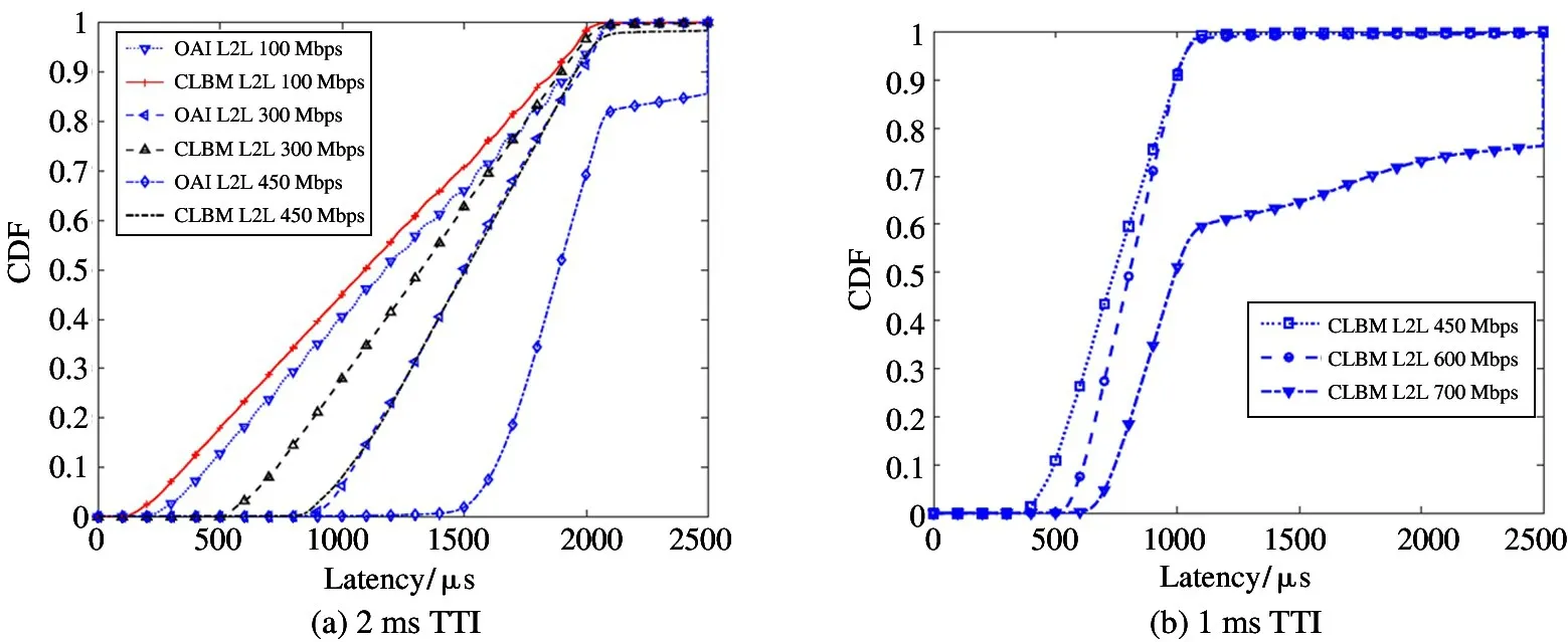
Fig.6 L2L delay CDF from PSperf with 2ms and 1ms TTI at different throughput
4 Conclusion
Motivated by the high data rates and low latency requirements for the 5G protocol stack,CLBM,a cross-layers memory buffer optimization scheme,is proposed for supporting a high-efficiency process in L2 of user plane.The CLBM can prolong lifetime of the PDU buffer and decrease the frequencies of memory request with lower CPU usage and processing delay.Moreover,a general evaluation framework(i.e.,PSperf)for the performance profiling of 5G radio protocol stack is proposed.Extensive experiments have been carried out based on proposed framework in order to evaluate the benefit of the CLBM.It has been shown the CLBM strategy reduces the CPU usage of RLC,PDCP and MAC layer significantly up to 20.6%,63.4% and 38.8%,respectively.In addition,the latency metric has also been evaluated at different TTI size and throughput.The results show that the delay for the UL protocol process has been reduced distinctly at various offered load and scheduling intervals.
The current work focuses on further enhancements to CLBM scheme for DL protocol stack processing in UE with PSperf.Indeed,considering the independence of PSperf,it can be generalized to a wide variety of protocol stacks(e.g.,gNB PS of OAI)for performance fine-tune evaluation.
杂志排行
High Technology Letters的其它文章
- Research on buffer structure and flow field simulation of swash plate plunger type hydraulic transformer①
- Effect of integral squeeze film damper on vibration and noise of spur gear with center-distance error①
- Workspace optimization of parallel robot by using multi-objective genetic algorithm①
- Design and implementation of gasifier flame detection system based on SCNN①
- A simplified hardware-friendly contour prediction algorithm in 3D-HEVC and parallelization design①
- Joint utility optimization algorithm for secure hybrid spectrum sharing①