Workspace optimization of parallel robot by using multi-objective genetic algorithm①
2022-02-11WANGJinhong王进洪LEIJingtao
WANG Jinhong(王进洪),LEI Jingtao②
(*School of Mechatronic Engineering and Automation,Shanghai University,Shanghai 200444,P.R.China)
(**Shanghai Key Laboratory of Intelligent Manufacturing and Robotics,Shanghai 200444,P.R.China)
Abstract
Key words:parallel robot,multi-objective genetic algorithm,workspace optimization
0 Introduction
Compared with traditional serial robots,parallel robots have the advantages of good rigidity,high load capacity and high accuracy,which are widely used in motion simulators,machining machines,manufacturing lines,space docking,and medical applications[1].
Generally,the workspace of parallel robots is limited by the branch chains.To ensure the flexibility and operability of the end-effector,it is important to make the workspace as large as possible to meet the operation requirements.The singularity will affect the performance of parallel mechanism seriously[2],so it is necessary to optimize the robot parameters to get a large and singularity-avoided workspace.
Many scholars have studied workspace optimization of parallel robots.Rios et al.[3]proposed a twostage optimization method based on a bionic algorithm for designing a Stewart platform.Gao et al.[4]used genetic algorithms and artificial neural networks for dimensional optimization of spatial six-degree-of-freedom parallel robots.Refs[5-8]have used algorithms such as particle swarm algorithms and genetic algorithms for the optimal design of several types of parallel robots using the workspace,stiffness,load-bearing capacity and dynamic performance parameters as objective functions.Li et al.[9]used a multi-objective particle swarm algorithm to find the optimal singularity-free path.Chi et al.[10]optimized the design variables of a parallel manipulator in terms of both workspace and stiffness.Tu et al.[11]used genetic algorithm to optimize a bumper based on Stewart platform for an inertial navigation system to improve the recovery accuracy.Nabavi et al.[12]used dexterity,kinetic energy and improved workspace index as objective functions for optimization to obtain better workspace and mechanical properties for a general-purpose 6-prismatic-universal-spherical(PUS)parallel robot by using a multi-objective genetic algorithm.Liu et al.[13]analyzed the parametric performance mapping of high-speed parallel robots and optimized the performance parameters of the driving system based on the proposed mapping.Mazare and Taghizadeh[14]used genetic algorithm and harmony search algorithm to optimize the design of Delta parallel robot to obtain larger workspace size and good dynamic performance.Erylmaz and Omurlu[15]used a sequential quadratic programming approach to parametrically optimize the parameters of the 3-universal-prismaticuniversal(UPU)platform in order to maximize the reachable workspace and avoid singularity patterns as much as possible,and finally obtained the optimal motion parameters.Fan et al.[16]proposed a safe workspace verification algorithm and analyzed the singularities of Stewart mechanism in 16 typical extreme poses to provide a reference for optimal design.
In this paper,the workspace of the 6-UPU parallel robot with the fixed orientation is studied.Firstly,the effective workspace is defined.Secondly,the boundary search algorithm and subspace extraction method are adopted to calculate the effective workspace.Thirdly,the effective workspace height(EWH)and global condition number index(GCI)are selected as the optimization objective functions,and the geometric parameters of the robot are optimized by non-dominated sorting genetic algorithm II(NSGA-II).Finally,the optimized results are verified by four indicators of the robot.
1 Inverse kinematic modeling
1.1 6-UPU parallel robot
The 6-UPU robot configuration consists of a fixed platform,a moving platform,six telescopic branch chains and twelve hinges,as shown in Fig.1(a).The single branch chain of the robot is shown in Fig.1(b).
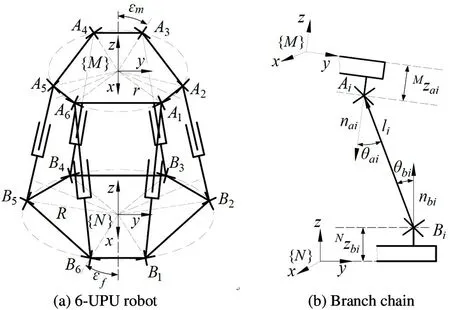
Fig.1 Robot configuration
The fixed platform coordinate system{N}and moving platform coordinate system{M}are located at the center of the fixed platform and moving platform,respectively.The hinge points of fixed and moving platform are defined asBiandAiin counterclockwise direction,respectively.The position vector of each hinge point of the fixed and moving platform are defined asbiandai.The position vector of thei-th branch chain is defined asli(i=1,2,…,6).
The position and orientation of the moving platform can be expressed by a vector:

The symbols of the geometric parameters are shown in Table 1.
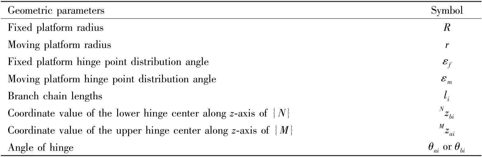
Table 1 Geometric parameters
1.2 Inverse kinematics
1.2.1 Inverse solution
The inverse solution of parallel robot is solved by the vector equation method.The length of each branch chain is calculated according to the position and orientation of the moving platform.
The vector diagram ofi-th branch chain is shown in Fig.2.The vector equation ofi-th branch chain is
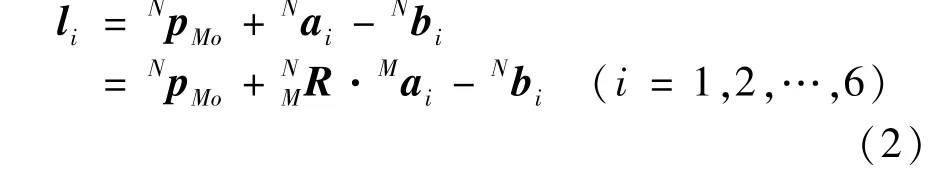
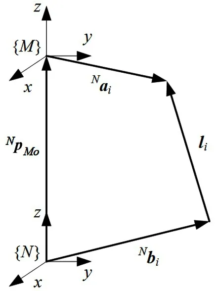
Fig.2 Closed-loop vector diagram of i-th branch chain
1.2.2 Velocity analysis
Derivating both sides of Eq.(2)yields:

whereviis the velocity vector of the electric cylinder of the branch chain;vMoandωMare the linear velocity vector and angular velocity vector of the moving platform,respectively.
Multiplying both sides of Eq.(3)by the directional unit vector of the branch chain,the velocity of branch chain is derived as
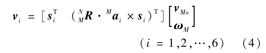
wheresiis the directional vector of each branch chain.
The velocity inverse solution can be written as
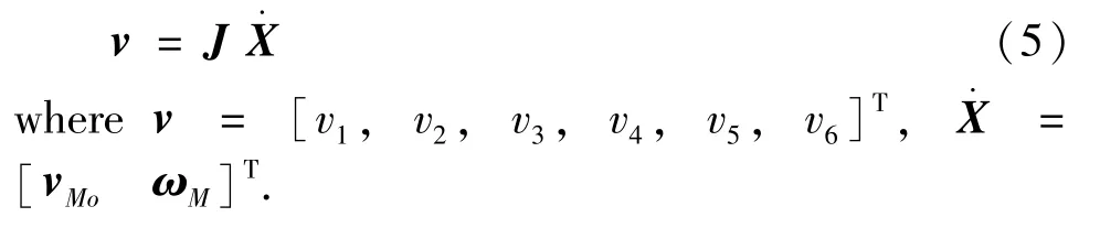
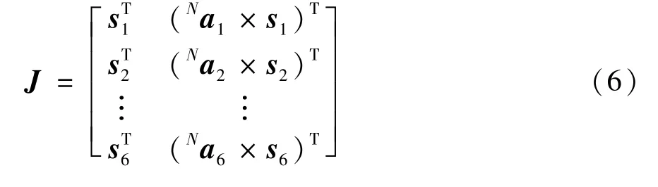
Then the velocity Jacobi matrix of the robot is derived as
2 Effective workspace
2.1 Effective workspace introduction
For the robot fixed-orientation workspace,there is a part of shaded area shown in Fig.3,in which the robot’s motion path is partly discontinuous,so this part is almost unusable.Therefore,the area with continuous paths in the fixed-orientation workspace is defined as the effective workspace.
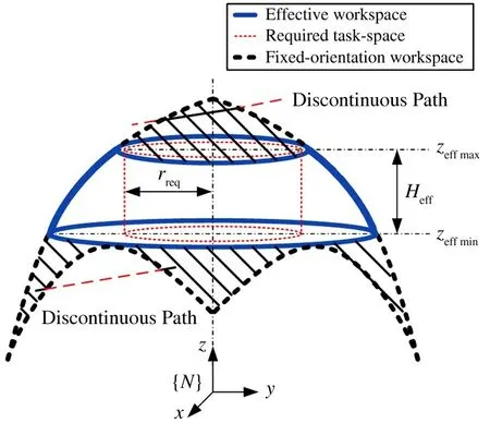
Fig.3 Diagram of the effective workspace
It is assumed that the required task-space of the robot operation task is a cylinder shown in the area of the thin dotted line in Fig.3.The radius of the cylinderrreqis used to reflect the size of the required taskspace.
The area in the real line shown in Fig.3 is effective workspace,it should be larger than the required task-space so as to meet the operating task requirements.
The effective workspace of the robot is composed of a series of effective subspaces.For each effective subspace,it should satisfy that the vertical distance from any boundary point toz-axis is greater than or equal to the radius of the required task-space:

where‖·‖2is the 2-norm of a vector,pjis the vector ofj-th boundary point in subspace,rreqis the radius of the required task-space,mis the number of boundary points in a subspace.
EWH can be used to reflect the volume of the area satisfying required task-space.EWH can be obtained as

where,zeffmaxis the maximum value of effective subspace inz-axis,zeffminis the minimum value of effective subspace inz-axis.
2.2 Effective workspace calculation
The center point of the moving platform is selected as the reference point to study the effective workspace.Firstly,the boundary points of the robot workspace can be obtained by the boundary search algorithm.Secondly,the effective workspace can be calculated by the subspace extraction method.
2.2.1 Boundary search algorithm
(1)All known geometric parameters are input,then the given orientation angle is input,the search range of the robot workspace and the search step are initially determined according to the geometric parameters.The polar coordinate system is used to describe the workspace.
(2)According to the search step described above,the search space is divided into several subspaceszi.
For a subspace,it can be divided into a number of points by pole angle and pole diameter.Each point can be judged whether it is in the workspace according to the constraints after inverse kinematics.The boundary point can be obtained and saved to the boundary point set.
2.2.2 Subspace extraction method
(1)After obtaining all boundary points in the plane ofzisubspace,Eq.(7)is used to judge whether the subspace is an effective subspace.If yes,save all boundary points in the plane to the set of effective boundary points before proceeding to the next step;if no,proceed to the next step direct.
(2)Determining whether the subspace plane has reached the highest value of the search range.If yes,then all effective workspace point sets are obtained;if no,then turn to the boundary search algorithm to search the next subspace plane.
(3)The boundary points are saved to the corresponding point sets,then the workspace parameter,EWH,can be further obtained by calculating the point sets.
The calculating flowchart of the effective workspace is shown in Fig.4.
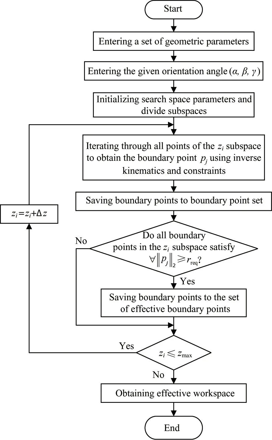
Fig.4 Calculating flowchart of the effective workspace
When the moving platform of the robot is at the initial orientation(0°,0°,0°),and a set of parameters of robot is set asR=150 mm,r=90 mm,εf=15 °,εm=15 °,li=350-500 mm,Nzbi=60 mm,Mzai=40 mm,θai=0-40 °,θb i=0-40 °,the required task-space radius is assumed asrreq=50 mm,the calculation result of the effective workspace is shown in Fig.5.

Fig.5 Effective workspace of the robot with the moving platform at the initial orientation
3 Workspace optimization
The multi-objective genetic algorithm NSGA-II with the properties of a fast non-dominated sorting procedure and an elitist strategy[17]is adopted to optimize the robot’s workspace.
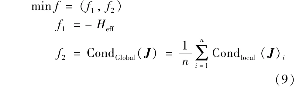
3.1 Objective functions
Two indexes are selected as the objective functions.As EWH can reflect the volume of the area satisfying required task-space,it is selected as an objective function.GCI indicates the dexterity of the robot,which is an average value of the local condition number index(LCI)of Jacobi matrix.The smaller GCI is,the better the robot’s dexterity is.
To avoid the robot from singularity,GCI is selected as the other objective function.
3.2 Design variables and constraints
Eight geometric parameters of the robot related to the objective functions are summarized in Table 1.For simplicity,the design variables are reduced to four,i.e.the moving platform radiusR,the fixed platform radiusr,the moving platform hinge distribution angleεm,and the fixed platform hinge distribution angleεf.
The constraints of optimization are

3.3 Optimization results
After optimization,two objective function values are shown in Fig.6.
It can be seen from Fig.6 that while the absolute value of EWH increases,GCI increases,so it is difficult to obtain larger workspace and better dexterity at the same time.Ten sets of the individuals with two kind of different orientation angles from Fig.6 are shown in Table 2 and Table 3,respectively.
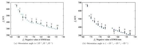
Fig.6 Two objective function values after optimization

Table 2 Ten sets of individuals with the orientation angle(15 °,15 °,15 °)

Table 3 Ten sets of individuals with the orientation angle(-15 °,-15 °,-15 °)
From Table 2 and Table 3,it can be seen that when two objective functions are the middle values,the robot not only has larger workspace,but also has better dexterity.Therefore,No.5 individual in Table 2 and No.6 individual in Table 3 are selected as the optimal individuals.
The final optimization result can be determined by averaging the optimal parameters obtained with two orientation angles.The optimized parameters of the robot are shown in Table 4.
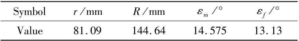
Table 4 Optimized parameters
4 Validation
Changing the orientation angles of the moving platform around thex-axis orz-axis from-30 ° to+30 ° by 1° step,the optimization results are verified by calculating four indicators.As the robot rotation around thex-axis is similar to that around they-axis,the orientation taking around they-axis is omitted.
Selecting four indicators for optimization verification,which are fixed-orientation workspace volume(FWV),EWH,effective workspace volume(EWV)and GCI,EWH and GCI can be calculated by Eq.(8)and Eq.(9),while FWV and EWV are calculated by Eq.(11)and Eq.(12)[18],respectively.
The parameters of robot before optimization are set asr=93.3 mm,R=174.29 mm,εm=22.03°,εf=10.53 °,and the optimized parameters are shown in Table 4.The calculation results of four indicators are compared as shown in Fig.7.The abscissa represents the rotation angle of moving platform aroundx-axis orz-axis.
Fig.7 Comparison of four indicators(before and after optimization)
Fig.7 shows that FWV,EWH and EWV increased and GCI decreased for all orientation angles used for validation.Specifically,FWV,EWH and EWV increased by 32.4%,17.8%,and 72.9% on average,respectively,and GCI decreased by 6.8% on average.It is demonstrated that the optimization parameters enable the robot to have reasonable workspace and better dexterity.
5 Conclusions
(1)The inverse kinematic of the 6-UPU parallel robot is derived,and the effective workspace solving method is presented,which is the boundary search method and subspace extraction method.
(2)The NSGA-II is adopted to optimize the robot parameters with two objective functions,which are EWH and GCI.A set of optimal parameters of parallel robot can be obtained.
(3)Four indicators of the robot before and after optimization with different orientation angles are compared.The results show that FWV,EWH and EWV increased,GCI decreased.The results show that the workspace optimization method is reasonable.
杂志排行
High Technology Letters的其它文章
- Research on buffer structure and flow field simulation of swash plate plunger type hydraulic transformer①
- Effect of integral squeeze film damper on vibration and noise of spur gear with center-distance error①
- Design and implementation of gasifier flame detection system based on SCNN①
- A simplified hardware-friendly contour prediction algorithm in 3D-HEVC and parallelization design①
- An efficient cross-layer buffer management optimization scheme for 5G protocol stack①
- Joint utility optimization algorithm for secure hybrid spectrum sharing①