Steganography based on quotient value differencing and pixel value correlation
2022-01-12ReshmaSonarGandharbaSwain
Reshma Sonar | Gandharba Swain
Department of Computer Science and Engineering,Koneru Lakshmaiah Education Foundation,Guntur,Andhra Pradesh, India
Abstract Pixel value differencing (PVD) steganography techniques produce imperceptible stegoimages. Most PVD-based techniques have a fall-off boundary problem (FOBP). To avoid FOBP, a steganographic scheme is presented that combines the quotient value difference(QVD)with pixel value correlation(PVC).It performs data embedding in two stages on 3 × 3 size pixel blocks. The first stage of the embedding procedure performs QVD and remainder substitution on five pixels.These five pixels are central pixel and it's neighbours on the left, right, upper, and lower sides. Based on the new values of these five pixels,the PVC embedding procedure is applied on the remaining four corner pixels of the block. The experimental results are found to be improved. The hiding capacity is high that is 3.92 bits per byte with an acceptable peak signal-to-noise ratio value. A security check was performed using two tests: (i) a regular-singular (RS) test, (ii) a pixel difference histogram (PDH) test. The experimental outcomes demonstrate that PDH curves of the stego-images do not have a zigzag shape, that means the PDH test could not detect this steganography technique. Furthermore, the RS curves show that the RS test could not detect this steganography technique.
1 | INTRODUCTION
The Internet is mostly used for data communication. Thus,security approaches are highly essential to safeguard data from unauthorized users. Techniques such as steganography can be useful to transmit data securely by hiding them in image,audio,and video files [1]. Data hiding inside a file such as an image should be done carefully without changing its statistical properties [2]. If the statistical properties are restored, the image will look innocuous and will not attract the attention of attackers. Least significant bit (LSB) substitution is a popular technique in steganography.It is simple but can be detected by the regular-singular (RS) test [3]. Pixel value differencing(PVD)steganography is equally popular.It was initiated by Wu and Tsai in 2003 [4]. This technique uses the pixel value difference in a block of two pixels to measure their hiding capacity (HC), and then hides the secret bits. However, this technique can be detected by a pixel difference histogram(PDH) test [5]. The PDH test is a two-dimensional (2-D)graph that considers the pixel difference and its frequency in the horizontal and vertical axes.If this curve is not smooth(it appears as a zig-zag) it is suspected that the image contains hidden data.The principal objective in the PVD technique is to recognize noise-tolerant pixel groups of the image and embed a larger number of bits in them. To hide relatively larger number of bits, PVD steganography with 2 × 2 size pixel block was described in Lee et al. [6]. To improve the HC and security,the PVD concept is applied on 3×3 size pixel blocks[7]. Furthermore, modified LSB substitution is applied with multi-directional PVD to improve the HC and security [8].
Luo et al. [9] discussed a PVD steganography mechanism on 1 × 3 size pixel blocks. They used a variable range table unlike Wu and Tsai. The minimum and maximum bounds for a pixel range are decided by considering the pixel values in the block. Thus, it is different for different blocks. Hence, they named it as adaptive PVD. This principle was extended to larger size blocks such as 2 × 2 and 3 × 3 to improve performance [10], but block sizes of 2 × 3 and 3 × 2 yielded optimum performance [11]. In general,these adaptive PVD techniques do not possess appreciable HC. Liao et al. [12] discussed an adaptive LSB substitution scheme in 2 × 2 blocks in which the number of LSBs used depends on the mean pixel value difference in that block.However,the performance could be further improved using 3× 3 size blocks [13].
Wu et al. showed that in an image, highly textured regions can accommodate greater changes, in which PVD embedding should be applied and smooth regions can also hide larger number of bits,where LSB substitution can be applied[14].As a result, both the HC and peak signal-to-noise ratio (PSNR)could be increased. Yang et al. [15] noticed that the technique in Wu et al.[14]identifies more than 90%of blocks as smooth blocks and less than 10% of blocks as highly textured.Therefore, ultimately, it replaces LSBs in more than 90% of blocks. Hence, the RS test could detect it. Khodaei and Faez[16]considered three consecutive pixels to be a block and used LSB substitution on the pixel in the middle position and PVD on two corner pixels of the block.There are two comments on this technique:(i)it is detected by a PDH test,and(ii)it has a fall-off boundary problem (FOBP). Khodaei and Faez’s principle has been carried ahead and applied with larger-size blocks such as 2×2 and 3×3[17,18]to improve the HC and PSNR and protection against the PDH test.
A kind of PVD technique known as modulus functionbased PVD (MFPVD), proposed by Wang et al. [19], uses the remainder value instead of the pixel value difference to hide the secret bits. This technique also provides greater HC with minimum distortion. Zhao et al. [20] used indeterminate equations in MFPVD to improve the PSNR. Wang et al.’s mechanism [19] possesses some range mismatch issue. Thus,Swain [21] proposed an MFPVD mechanism in bigger size blocks like 2 × 3 to avoid this problem. This improved technique is superior in terms of HC and PSNR and attack resistance. From a 2 × 2 size block, Yang et al. formed pairs in diagonal, vertical, and horizontal directions and applied PVD to improve performance[22].Pradhan et al.[23]combined the three approaches, (i) LSB substitution, (ii) PVD, and (iii)exploiting modification direction judiciously to achieve better performance. Jung [24] proposed a new steganography approach with 1 × 2-size pixel blocks using LSB substitution in LSB positions and PVD in most significant bits (MSBs)positions to achieve greater HC. Swain [25] extended Jung’s technique to 3 × 3-size blocks to achieve a higher HC.
When hiding data in color images, we generally treat each color component of a pixel independently and hide data in them.By doing this, correlations among the three channels will be disturbed,To avoid this problem,Tang et al.[26]proposed that different color channels of the same pixel should be changed towards an increasing or decreasing direction consistently.Furthermore,Li et al.[27]said that if in textured regions of image modifications of differentpixelvalues are done towards the same direction, security can be improved. Sahu et al. [28] presented dual stego-image embedding, in which data are hidden in two mirror images based on LSB matching. Elhoseny et al. [29]proposed applying steganography for the secure transfer of health care data.Li et al.[30]also proposed hiding data inside a set of images in social networks.
Watermarking is another aspect of hiding data in which the main concern is copyright protection and authentication.Singh reviewed potential challenges and applications in data hiding techniques[31].Some important applications of watermarking are mobile devices, 3D objects, telemedicine, hardware protection, and cyber-physical systems. Singh et al. proposed an encryption and compression-based watermarking scheme to improve the security of digital documents [32]. Furthermore,Singh and Kumar proposed an encryption and compressionbased watermarking scheme to verify content along with copyright protection in e-governance [33]. To achieve authentication and integrity, multiple-watermarks can be embedded in an image[34],so that the required bandwidth will be decreased and security will be improved.
2 | RELATED WORK, PROBLEM STATEMENT, AND CONTRIBUTION BY AUTHORS
2.1 | Jung’s [24] LSB + PVD technique
Jung [24] divided the image into disjoint blocks, each containing two adjacent pixels(P1, P2).He divided the eight bits of a pixel into two parts, with the k LSBs as one part and the remaining (8-k) MSBs as another part. Then, he performed substitution on k LSBs and PVD on (8-k) MSBs. The procedure of embedding is detailed next.
The integer equivalent of k LSBs of P1is computed as R1= P1mod 2k. Similarly, the integer equivalent of k LSBs of P2is computed as R2= P2mod 2k. Furthermore, the integer equivalent of (8-k) MSBs of P1is computed as Q1=P1div 2k. Similarly, the integer equivalent of (8-k) MSBs of P2is computed as Q2= P2div 2k. Suppose, R′1, R′2, Q′1and Q′2are the stego-values of R1, R2, Q1and Q2, respectively. R′1is computed by taking k secret data bits and converting them into a decimal value. Similarly, R′2is computed by taking the next k secret data bits and converting them into a decimal value.
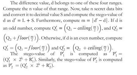
To perform data hiding in Q1and Q2, compute d =|Q1- Q2|. The range table is composed of four ranges:{0, 7}, {8, 15}, {16, 31}, and {32, 63}. These ranges are represented in the form of{L,U},where L is the lower bound(LB) and U is the upper bound of a range. The embedding capacity in a range is determined as n = log2(U-L+1).
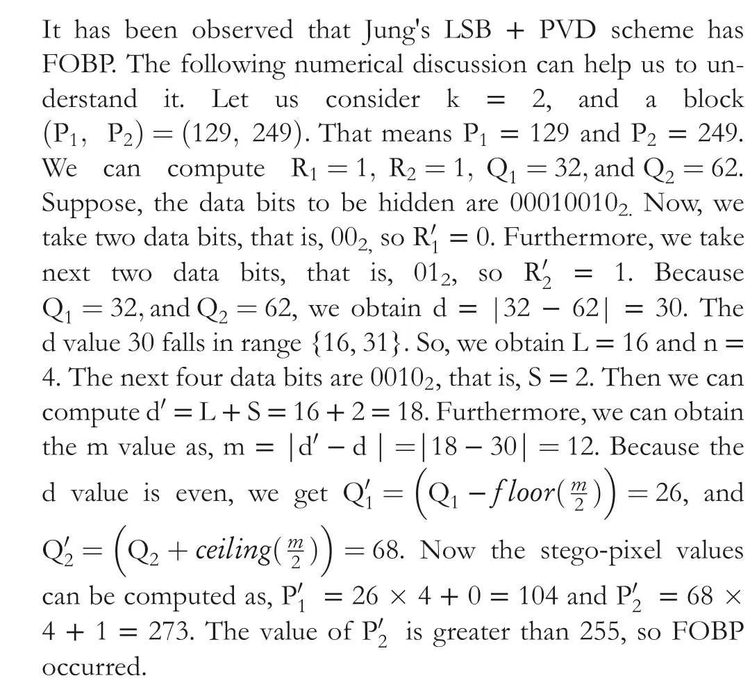
2.2 | Problem statement
2.3 | Contribution of this paper
Most PVD steganography techniques have FOBP, including that of Jung. To avoid FOBP, this work proposes a steganography technique by exploring 3×3-size pixel blocks.The idea of Jung is adopted to divide a pixel into two parts.A pixel value correlation (PVC) is intertwined with the quotient value differencing (QVD). The main contribution is an appropriate intertwining of QVD and PVC such that the FOBP is avoided.In addition, advantages are achieved:
· The RS test could not detect the proposed QVD + PVC technique.
· The PDH test could not detect the proposed QVD+PVC technique.
· A fair balance between HC, and PSNR is achieved.
Section 3 represents the proposed work(the QVD+PVC scheme), and Section 4 discusses a numerical example of it.The results and performance analysis are presented in Section 5 and the conclusions are drawn in Section 6.
3 | PROPOSED QVD + PVC SCHEME
3.1 | Data hiding procedure
The original image is accessed in raster-scan order and 3 × 3 size dis-joint pixel blocks are formed as shown in Figure 1a.The data hiding in a block are done in two stages. In stage 1,QVD and remainder substitution is performed,and in stage 2,PVC is performed.
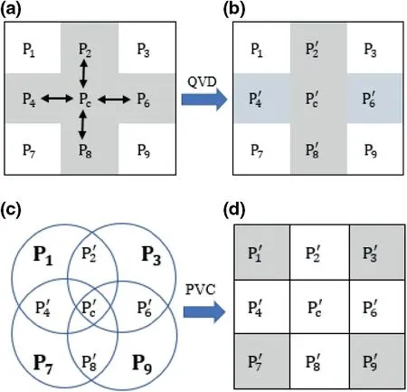
FIGURE 1 (a) Sample block; (b) Stego-block after quotient value differencing; (c) Four clusters; (d) Stego-block after pixel value correlation
In stage 1 of the hiding procedure, a QVD approach is applied on pixels Pc, P2, P4, P6, and P8. If FOBP occurs,then the QVD procedure is undone and 4-bit LSB substitution is applied on Pc, P2, P4, P6, and P8. Steps 1–8 describes stage 1 of the embedding procedure.
Step 1 From each of pixels Pc, P2, P4, P6, and P8two sets of values,(i)remainders,and(ii)quotients,are calculated using Equations (1) and (2), respectively.

In Equation(1),Ri=Pimod 4,for,i=2,4,6,and 8.This means that R2= P2mod 4, R4= P4mod 4, R6= P6mod 4,and R8=P8mod 4.In Equation(2),Qi= Pidiv 4,for,i=2,4, 6, and 8. This means that Q2= P2div 4, Q4= P4div 4,Q6= P6div 4,and Q8= P8div 4.Here mod and div stand for remainder and quotient division respectively. For example,35 mod 4 = 3, and 35 div 4 = 8.
Step 2 One data bit is taken from the secret binary bit stream, and appended to the left of indicator bit 1. These two bits are transformed to a decimal digit and are treated as the stego-value for Rc. Let it be represented as R′c. Take next two data bits, convert them to decimal and denote this as R′2. Again, take the next two data bits, convert them to decimal, and denote this as R′4. Similarly for R′6, and R′8. These are the stego-values for R2, R4, R6, and R8,respectively.
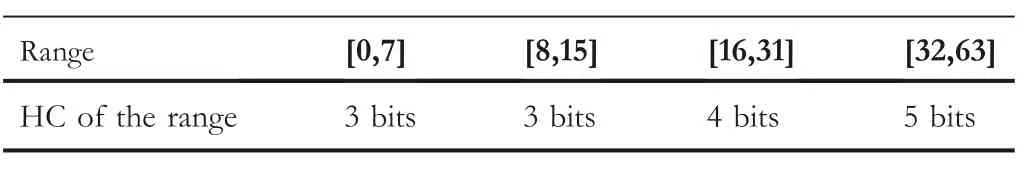
TABLE 1 Range table
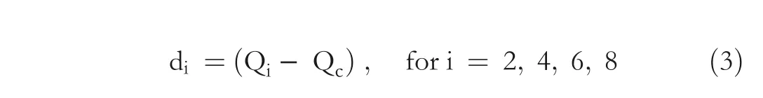
Step 3 Four quotient value differences are calculated using Equation (3).The meaning of Equation(3)is that d2=(Q2- Qc),d4=(Q4- Qc), d6= (Q6- Qc), and d8= (Q8- Qc).
Now consider the range in Table 1. Suppose the absolute difference value |di|,for i = 2, 4, 6, 8 should fall into a specific range out of the four ranges.Let Liand nidenote the LB, and the HC of that range.


For i = 3, this statement means, take n3data bits and convert them to a decimal digit b3.After hiding b3in P3,the stego-value is P′3= P3- P3mod 2n3+ b3.
For i = 7, this statement means, take n7data bits and convert them to a decimal digit b7.After hiding b7in P7,the stego-value is P′7= P7- P7mod 2n7+ b7.
For i = 9, this statement means, take n9data bits and convert them to a decimal digit b9.After hiding b9in P9,the stego-value is P′9= P9- P9mod 2n9+ b9.
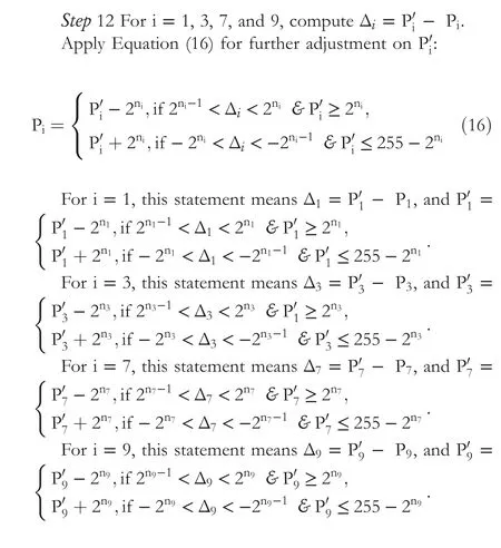
Figure 1d is the resultant stego-block for the original block shown in Figure 1a.
3.2 | The extraction procedure
Figure 1d represents a block from which we need to extract hidden data.It is performed in two stages.Stage 1 is the QVD and remainder extraction procedure, and stage 2 is the PVC extraction procedure.

Step 5 For i = 1, 3, 7, and 9, compute ni, as shown in Equation (24). Furthermore, set ni=4, if ni≥4:

4 | A STEP‐BY‐STEP EXAMPLE
Let us embed secret binary data (0 01 10 10 11 011 001 110 111 101 1010 0111 1000)2into a pixel block shown in Figure 2a.The pixel values are P1= 150, P2= 155, P3= 156,P4= 151, Pc= 157, P6= 158, P7= 152,P8= 160, and P9=162.
Step 1 Using Equation(1),Rc= Pcmod 4=157 mod 4=1,R2=P2mod 4=155 mod 4=3,R4=P4mod 4=151 mod 4=3,R6=P6mod 4=158 mod 4=2,and R8= P8mod 4 = 160 mod 4 = 0.

FIGURE 2 (a) A 3 × 3 size original block, (b) The intermediate 3×3 size stego-block, (c) grouping of pixels, (d) final stego-block
Thus,we get Rc=1, R2=3, R4=3,R6=2,and R8=0.
Using Equation(2),Qc= Pcdiv 4=157 div 4=39,Q2=P2div 4=155 div 4=38,Q4= P4div 4=151 div 4=37,Q6=P6div 4=158 div 4=39,and Q8= P8div 4=160 div 4=40.
Thus, we get Qc=39, Q2= 38, Q4= 37, Q6= 39,and Q8= 40.
Step 2 The first bit from the secret binary data stream is taken and concatenated on left of indicator bit 1. Thus, we get 012. Transforming these two bits to decimal, we get R′c= 1. Taking next two bits of secret data and converting to decimal value we get R′2= 1. Taking the next two bits of secret data and converting to decimal value, we get R′4= 2. Similarly,we get R′6= 2, and R′8= 3. These values will be used as stego-values for Rc, R2, R4, R6, and R8accordingly.
Step 3 Using Equation (3), d2= (Q2- Qc)=(38-39)=-1, d4= (Q4- Qc)=(37-39)=-2,d6= (Q6- Qc)=(39-39)=0, and d8= (Q8-Qc)=(40-39)=1.
Thus,we obtain d2=-1, d4=-2, d6=0, and d8=1.
Furthermore,|d2|=1, |d4|=2,|d6|=0,and|d8|=1. Referring to Table 1, all |di| values (for i = 2, 4, 6, and 8)fall in range{0,7},so we get L2=0, n2=3, L4=0, n4=3,L6=0, n6=3, L8=0, and n8=3.
Step 4 Now taking next n2bits of secret data and converting them to decimal value, we get b2=3.Taking the next n4bits of secret data and converting them to decimal value,we get b4=1.Similarly,we get b6=6, and b8=7.

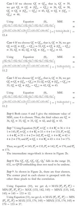
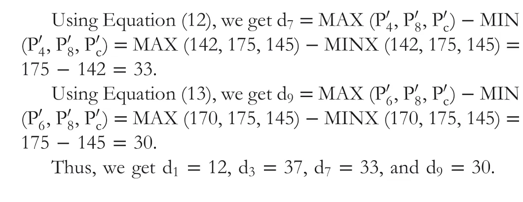
Step 10 Using Equation (14), because d1>1, so n1=log2d1=log212 = 3. Similarly, d3>1,n3=log2d3=log237 = 5. d7>1, n7=log2d7=log233 = 5. and d9>1, n9=log2d9=log230 = 4.
Thus, we get n1=3, n3=5, n7=5, and n9=4. Because n5≥4, and n7≥4, we can set n5=4, and n7=4. Finally, we have n1=3, n3=4, n7=4, and n9=4.
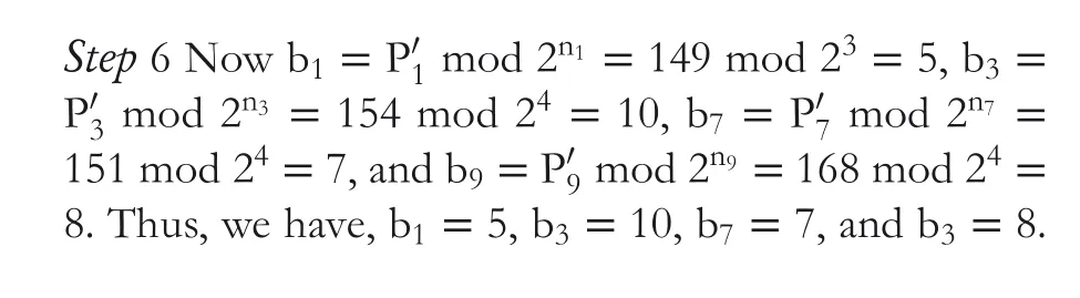
Step 11 Taking the next n1bits of data, we take 1012, and convert it to decimal value; then, we get b1=5. Similarly, take the next n3bits of data.We take 10102and convert it to decimal value, and we get b3=10. Take the next n7bits of data; we take 01112and convert it to decimal value, and we get b7=7. Take the next n9bits of data; we take 10002and convert it to decimal value, and then we get b9=8.
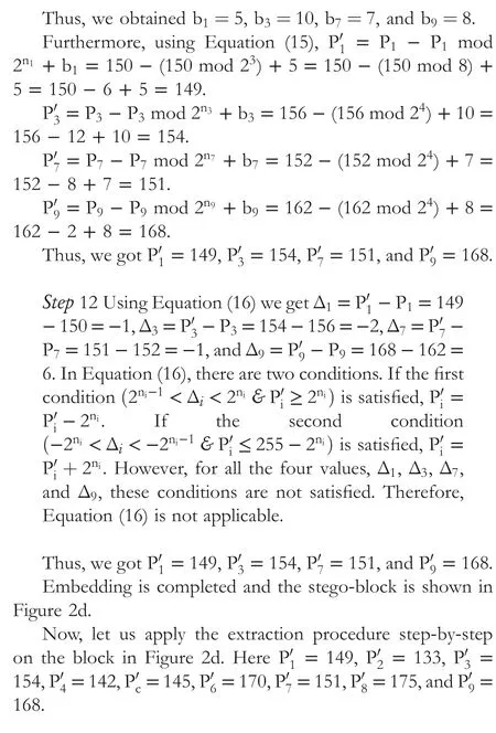

Thus, we got b2= 3, b4= 1, b6= 6, and b8= 7.
Now transforming b2to n2binary bits we get 0112. Similarly, transforming b4to n4binary bits, we get 0012. Transforming b6to n6binary bits,we get 1102,and transforming b8to n8binary bits, we get 1112. After appending these bits to EBDS, we get EBDS = 0 01 10 10 11 011 001 110 1112.

Transforming b1to n1binary bits we get 1012. Transforming b3to n3binary bits we get 10102.Transforming b7to n7binary bits we get 01112. Transforming b9ton9binary bits we get 10002. Append all of these bits to EBDS.
Hence,weobtainEBDS=0 01 10 10 11 011 001 110 111 101 1010 0111 10002.These are same as the embedded bits.
5 | EXPERIMENTAL RESULTS
This proposed QVD + PVC scheme is programmed in MATLAB and executed on a laptop computer. The configuration of the laptop computer is a i3 processor (2.30 GHz), 4 GB RAM, and 1000 GB hard disk. The operating system is Windows 10. The images fetched from SIPI data-base are utilized as test images. Figure 3 shows eight original images.Figure 4 represents the stego-images with their PSNR values.In each stego-images seven lakhs (700,000) bits of secret data are hidden. The results for these images are analyzed and compared with related existing techniques. These images are imperceptible and no visible marks are available in them to be detected as stego-images.
The efficacy of this proposed technique has been measured in terms of HC, PSNR, and quality index (QI).After embedding the secret bits inside the image, the distortion is measured in PSNR. It is calculated using Equation (25). In this equation m and n represents the image size, Pijis the original pixel, and Qijis the corresponding stego-pixel. For a color image, every byte can be assumed to be a unit of calculation, and then Equation (25)can be applied. The m value is 512 and the n value is 1536 for the test images:

The HC represents the number of data bits that the carrier image can conceal. The average number of bits that a pixel conceals is termed as bits per byte (BPB). The resemblance between the image before hiding and the image after hiding is termed the QI. Equation (26) can be used to measure QI.
where ¯P stands for the mean value of all pixels in the original image before hiding, and ¯Q is the mean value of all pixels of the stego-image.
Table 2 presents the computed values of quality parameters(PSNR, HC, QI, BPB, data hiding time, and data extraction time) of the proposed QVD + PVC scheme. The proposed scheme uses a combination of QVD and PVC for the first time in the literature.An HC of 3.92 BPB with an acceptable PSNR value greater than 30 decibels (dB) is remarkable. The proposed steganography scheme is a novel technique. The time complexity depends on,n(the length of secret data).Thus,it is an order of n,that is,O(n).Moreover,the time to hide 700,000 bits in different test images and extracting 700,000 bits from the stego-images is shown in last 2 columns of Table 2. The average embedding time is 15 s, and the average extraction time is 10.5 s.
Tables 3–5 present the values of the quality parameters(PSNR, HC, QI, and BPB) of the existing techniques[7, 16, 24, 25], and the proposed QVD + PVC scheme. Table 6 presents the average value of parameters of existing techniques [7, 16, 25], and that of Jung [24] along with the proposed QVD + PVC scheme. The technique of Pradhan et al. [7] is an eight-directional PVD based on the PVD of Wu and Tsai [4]. The HC of the proposed QVD + PVC scheme is higher than the technique of Pradhan et al. with a slight decrease in PSNR. The average estimated HC of the technique of Pradhan et al. is 1885371 bits (2.39 BPB),
whereas for the proposed QVD + PVC scheme it is 3088513 bits (3.92 BPB). Khodaei and Faez's [16] PVD technique is based on addition-subtraction logic; it is not based on Wu and Tsai's [4] PVD. The technique of Khodaei and Faez possesses higher PSNR, but it has a lower HC than the proposed QVD + PVC scheme. Swain's QVD technique [25]is also based on Wu and Tsai's [4] PVD. It operates on ninepixel blocks and performs the embedding operation in two different planes: (i) a remainder plane, and (ii) a quotient plane. Thus, the HC of this technique is slightly higher than the HC of the proposed QVD + PVC scheme. However, the proposed QVD + PVC scheme possesses higher PSNR than Swain's QVD technique. The average estimated PSNR of Swain's QVD technique is 33.06 dB, whereas for the proposed QVD + PVC scheme it is 35.94 dB. Jung's technique[24] is also based on Wu and Tsai's [4] PVD. The PSNR of Jung's technique is 50 dB, higher than the proposed QVD +PVC scheme, but the HC of Jung's technique is 3.39, lower than the proposed QVD + PVC scheme. Moreover, Jung's technique has FOBP, so extraction cannot be done correctly.This PSNR estimations is performed with 700,000 bits of data hidden in the stego-images for all of the discussed techniques.
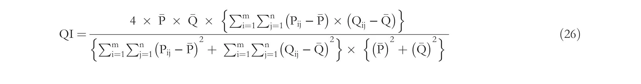
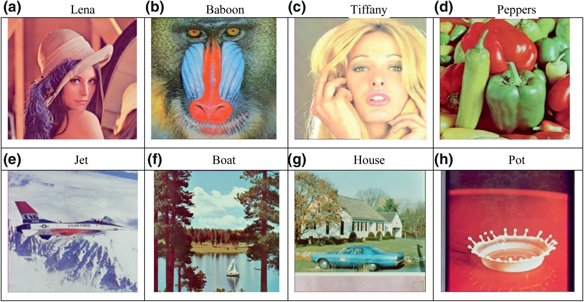
FIGURE 3 Original images
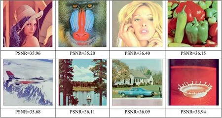
FIGURE 4 Stego-images
Figure 5 presents a bar chart distinguishing the PSNR and BPB of the proposed QVD + PVC scheme with the other schemes. The proposed QVD + PVC scheme fairly balances the PSNR and BPB.However, the technique of Pradhan et al.[7] possesses higher PSNR with lower BPB and the technique of Swain [25] possesses higher BPB with lower PSNR. The PSNR of Khodaei and Faez[16]is higher,but the HC is lower.Similarly,the PSNR of Jung[24]is higher,but the HC is lower.
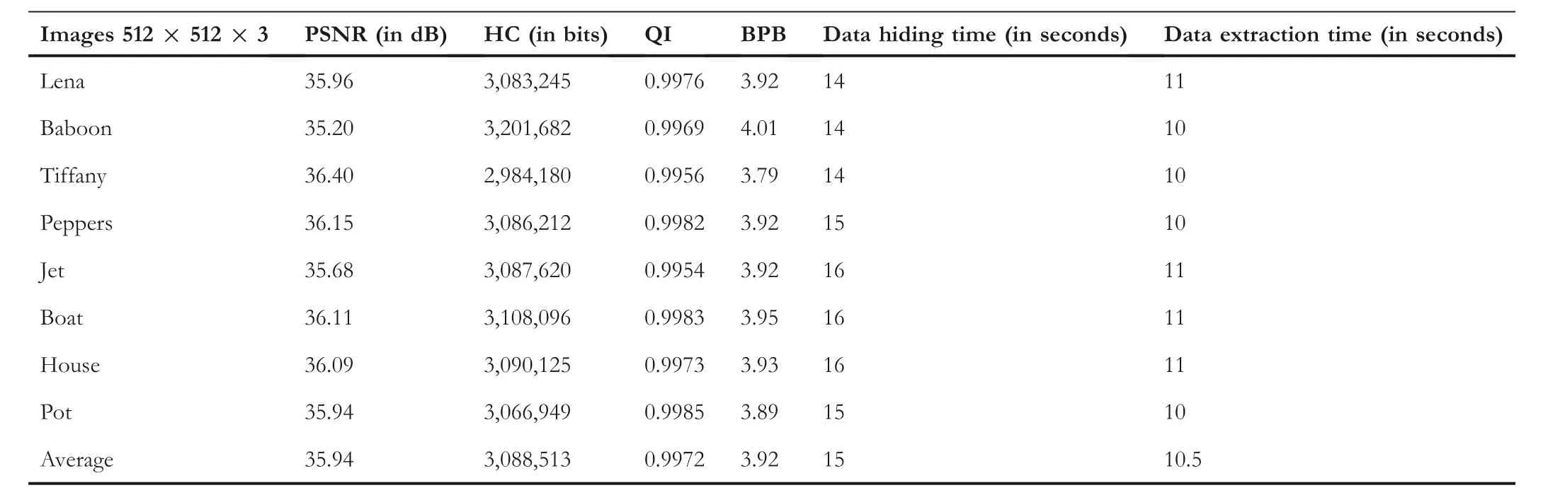
TABLE 2 Results of proposed QVD + PVC scheme
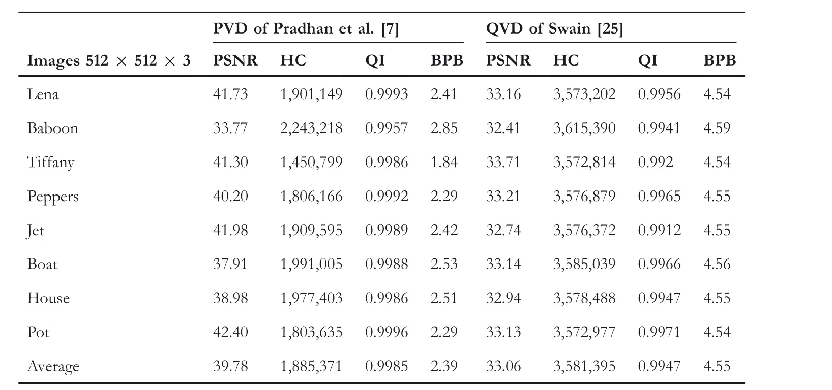
TABLE 3 Results of PVD of Pradhan et al. [7] and QVD of Swain technique [25]
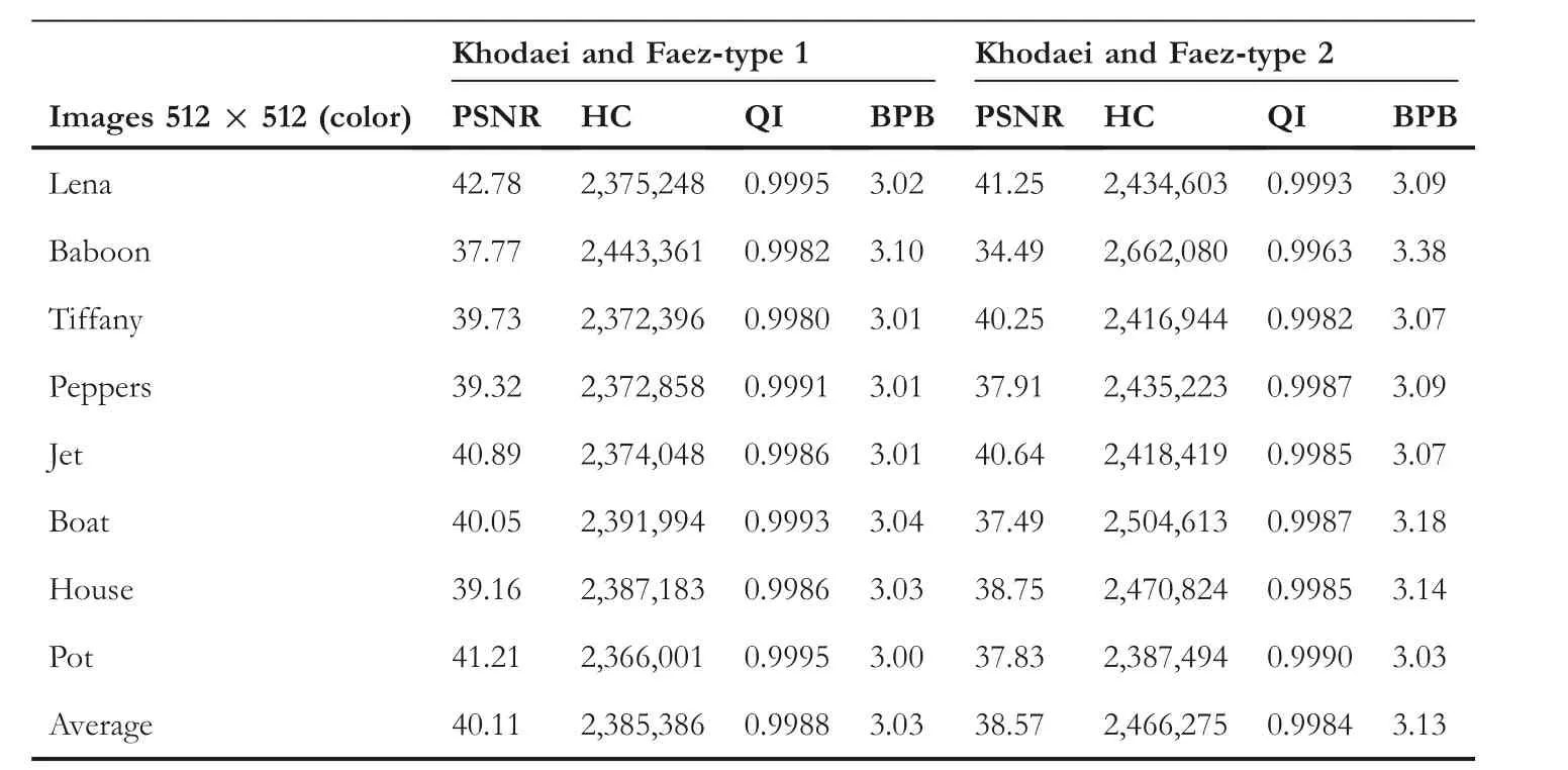
TABLE 4 Results for Khodaei and Faez's technique [16]
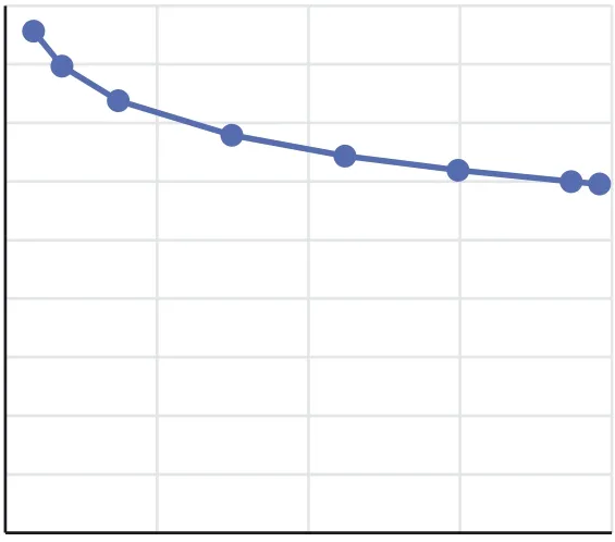
Table 7 represents the PSNR values of different stegoimages when different amounts of data are hidden. It can be noticed that when 140,000 bits of data is hidden in each of the images, the average PSNR is 42.80 dB. Similarly,when 280,000 bits are hidden, the average PSNR is 39.88 dB. When 560,000 bits of data is hidden, the average PSNRis 36.92 dB. When 1,120,000 bits of data is hidden, the average PSNR is 33.92 dB. When 16,80,000 bits of data is hidden, the average PSNR is 32.17 dB. When 2,240,000 bits of data is hidden, the average PSNR is 30.96 dB. When 2,800,000 bits of data is hidden, the average PSNR is 30.01 dB. When 2,940,000 bits of data is hidden, the average PSNR is 29.81 dB. Furthermore, Figure 6 represents capacity versus PSNR graph for Lena, Baboon, Tiffany, and Peppers images. From these graphs we can observe that the minimum PSNR value is nearly 30 dB.
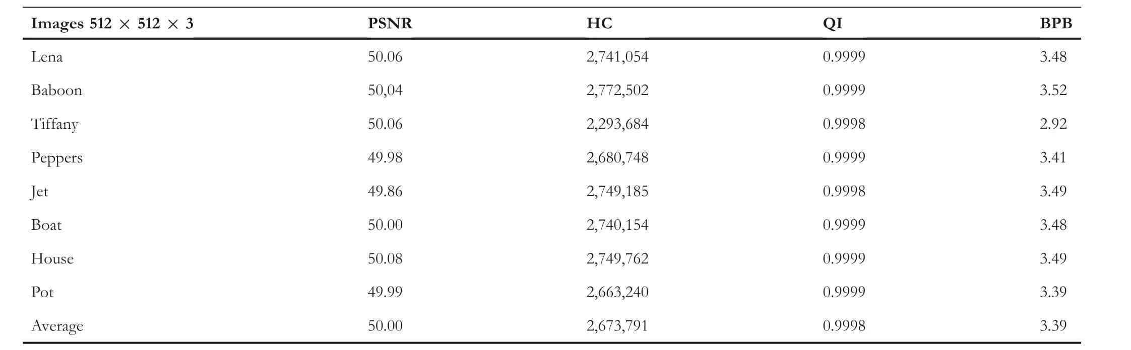
TABLE 5 Results of Jung's technique [24]

TABLE 6 Comparison of results

FIGURE 5 Comparison of PSNR (series 1) and BPB (series 2) of proposed technique with existing techniques. BPB, bits per byte; QVD, quotient value difference; PSNR, peak signal-to-noise ratio; PVD, pixel value differencing
The robustness of the proposed QVD + PVC scheme is verified by performing PDH and RS tests. The PDH test has been performed by referring to the procedure in Sahu and Sahu [35]. The PDH test is performed by plotting PDH graphs. The PDH graph is a 2D curve with pixel difference on X-axis and frequency on Y-axis. The literature says that the PDH graph for the original images will be smooth in nature, but the PDH graph for stego-images generated by PVD techniques will be zigzag [35]. For the proposed scheme, the PDH test for Lena, Baboon, Tiffany, and Peppers images are in Figure 7. In all four subfigures, the solid line curve represents the original image, and the dotted line curve represents the stego-image. The four subfigures show that there are no zigzags appearances in the PDHcurves of the four stego-images. Thus, the PDH test is unable to detect the proposed scheme.

TABLE 7 Capacity vs PSNR for various images in the proposed scheme
?
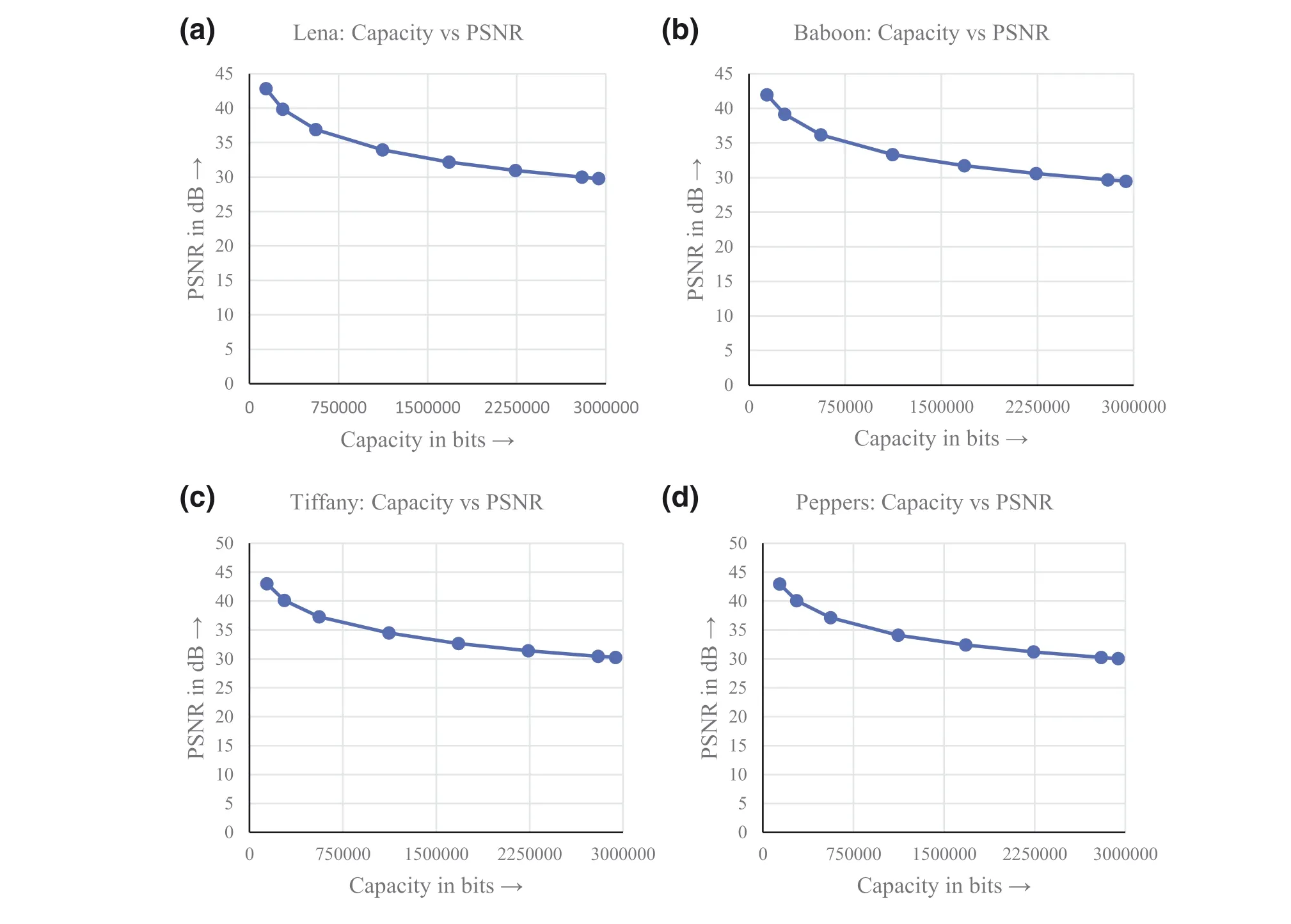
FIGURE 6 Capacity versus PSNR graph for the proposed QVD + PVC scheme: (a) Lena: capacity versus PSNR; (b) Baboon: capacity versus PSNR;(c)Tiffany:capacity versus PSNR,and(d)Peppers:capacity versus PSNR.QVD,quotient value difference;PSNR,peak signal-to-noise ratio;PVD,pixel value differencing
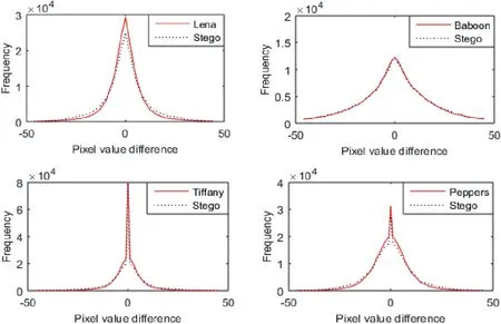
FIGURE 7 Pixel difference histogram test
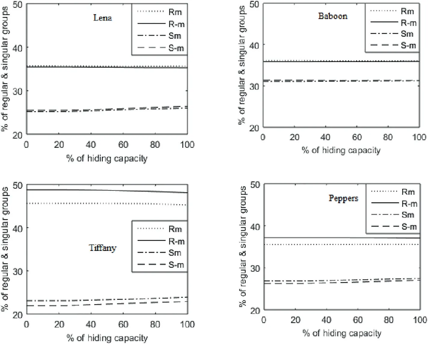
FIGURE 8 Regular-singular test
The RS test has been performed on the proposed scheme by referring to the procedure in Sahu and Sahu [35].The four parameters,Rm,R-m,Sm and S-m,were used.According to the RS test, if R-m- S-m>Rm - Sm, the RS test detects the steganography technique. If Rm ≈R-m>Sm ≈S-mis true,the steganography technique is undetected by the RS test.For the proposed QVD + PVC scheme, the RS test for the Lena, Baboon, Tiffany, and Peppers images have been shown in Figure 8, which shows in all four subfigures that Rm ≈R-m>Sm ≈S-mis true.Among these four images,Tiffany is a smooth image and Baboon is a textured image.Peppers and Lena are moderately smooth. Thus, from these observations it is evident that the RS test is incapable of detecting the proposed QVD + PVC scheme.
6 | CONCLUSION
A steganography scheme is described using the principles of QVD, and PVC. The proposed scheme splits the image into 3×3-size disjoint pixel blocks,and applies QVD and remainder replacement approach on five pixels: the central pixel and its neighbours in left,right,upper and lower positions.The stegovalues of these five pixels are used to apply the PVC approach on the four corner pixels. The experimental results are satisfactory. The HC is high with acceptable PSNR. The recorded BPB value is 3.95.In the proposed technique,the RS and PDH tests are applied to verify its security and robustness. The experimental results show that stego-image curvesare as smooth as that of the corresponding original image,so the PDH test is incapable of detecting this scheme.Furthermore,the RS curves demonstrate that Rm ≈R-m>Sm ≈S-mis true,so the RS test is also incapable of detecting this scheme.
ORCID
Gandharba Swain https://orcid.org/0000-0001-6586-1432
杂志排行

CAAI Transactions on Intelligence Technology的其它文章
- Constrained tolerance rough set in incomplete information systems
- Nuclear atypia grading in breast cancer histopathological images based on CNN feature extraction and LSTM classification
- A multi‐agent system for itinerary suggestion in smart environments
- Low-rank constrained weighted discriminative regression for multi-view feature learning
- Modified branch-and-bound algorithm for unravelling optimal PMU placement problem for power grid observability:A comparative analysis
- D‐BERT:Incorporating dependency‐based attention into BERT for relation extraction