Enhance sensitivity to illumination and synchronization in light-dependent neurons∗
2021-12-22YingXie谢盈ZhaoYao姚昭XikuiHu胡锡奎andJunMa马军
Ying Xie(谢盈) Zhao Yao(姚昭) Xikui Hu(胡锡奎) and Jun Ma(马军)
1Department of Physics,Lanzhou University of Technology,Lanzhou 730050,China
2School of Science,Chongqing University of Posts and Telecommunications,Chongqing 430065,China
Keywords: light-sensitive neuron,synchronization,energy consumption,bifurcation,neural circuit
1. Introduction
Each functional region in the brain contains a large number of neurons with specific biophysical functions. In fact,appropriate firing modes in isolated neuron and effective synapse coupling are critical to induce collective behaviors of neural networks for the functional regions, and thus safe body gaits can be regulated.That is,the collective neural activities of nervous system described by neural network[1–5]are dependent on the local kinetics and connection topology as well. Therefore, reliable biophysical neuron models and adjustable coupling channels are important to approach biological neurons and synaptic plasticity in the nervous system.Many of the previous neuron models[6–10]can reproduce and predict the main dynamical properties in the neural activities as those from biological neurons,and the effects of ion channels are considered.Indeed,electromagnetic field can be induced when intracellular and extracellular ions are propagating along the ion channels of cell membrane and diffusing in the cell. As a result,memristor[11–13]and Josephson junction[14,15]are considered as critical electric devices for building functional neural circuits for detecting the effect of electromagnetic field[16–20]on the neural activities. When thermistor[21,22]is connected to a branch circuit, the output voltage of neural circuit becomes dependent on the channel current across the thermistor and a thermosensitive neuron is obtained.[23–25]When the phototube is activated,the photocurrent will excite the neural circuit coupled by a phototube and then a light-sensitive neuron[26–28]is proposed for further investigating the mode transition under electromagnetic radiation and illumination. As reported in Ref. [29], a light-sensitive neuron can be controlled to keep pace with a thermosensitive neuron, and it threw lights on knowing the cooperation mechanism between different functional neurons. A piezoelectric actuator[30–32]can convert external vibration energy and mechanical force into electrical energy, which can be further used to drive motors. In addition,a piezoelectric ceramics can capture acoustic wave, and the neural circuit coupled by piezoelectric component[33–36]can be controlled by external vibration due to piezoelectric conversion,and an auditory neuron[37]can be obtained under piezoelectric effect.
For dynamical modelling and control in realistic systems,the physical evidences, principle and mechanism[38–40]are critical and much important. For example, the activation of chemical synapse[41–44]relies on the release of neurotransmitter and the calcium, and its physical mechanism can be associated with the occurrence of magnetic field in the cell.On the other hand, the activation and connection of electrical synapses[45–48]just trigger a setting of electric field and then voltage coupling via gap junction is switched on. In fact, capacitor connection between nonlinear circuits can induce electric field coupling and some physical evidences for explaining differential control mechanism[49]are provided,while inductive connection[50]via induction coil to nonlinear circuits can induce magnetic field coupling and integral control is explained. For further utilizing the physical properties of these electric components, hybrid synapse,[51–54]which is composed of resistor,capacitor and induction coil,is designed to connect neural circuits and then the energy pumping is controlled to adjust the synchronization stability.
As mentioned above,the channel current will regulate and excite the neural circuits with different scales and intensities when these specific functional components are incorporated into different branch circuits. In this paper,a phototube is embedded into one branch circuit of a simple neural circuit,and it is connected to the capacitor,and induction coil in series,respectively. That is,the output voltage across the capacitor and channel current across the induction coil will be controlled by the photocurrent,respectively.As a result,a class of photosensitive and light-sensitive neural circuit is obtained to reproduce the main dynamical property of biological neurons, and the firing modes are dependent on the electromagnetic wave. Furthermore, two light-sensitive neural circuits are coupled via electrical synapse,and the coupling channel is adjusted to stabilize synchronization. The Joule heat consumed along the coupling channel is also estimated,and the realization of synchronization stability between two light-sensitive neurons provides helpful guidance for knowing the cooperation between two eyes, and this investigation also throws lights on further designing artificial electric eyes and sensors under illumination.
2. Model and scheme
In Ref. [26], a phototube is connected to a resistor–capacitor–inductor(RLC)coupled neural circuit,and the phototube activated by external illumination can be regarded as a voltage source or current source, which is relative to the resistance of the resistor connected to the phototube. That is, the neural circuit is excited by the photocurrent even in absence of external stimulus. As shown in Fig. 1, the output voltage and the membrane potential of the light-sensitive neuron will be controlled by the photocurrent and external electromagnetic wave directly.

Fig.1. Case 1 Schematic diagram for the light-sensitive neural circuit(phototube connects to the capacitor in series).Vs,E,C,L,R,Rs and NR represent the external signal source, constant voltage source, capacitor, induction coil,linear resistors and nonlinear resistor,respectively. A and K denote the anode and cathode of the phototube, respectively, and photoelectrons are released from the cathode exposed to external electromagnetic radiation.
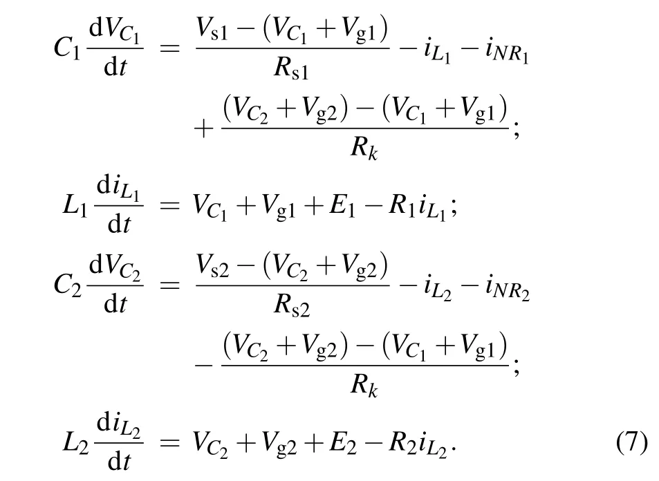
Guided by the physical Kirchhoff’s law,and the equations for the neural circuit in Fig.1 are obtained by

whereVC,iL,Vgmeasure the output voltage across the capacitor,channel current along the induction coil,photovoltage for the phototube, respectively. The channel current across the nonlinear resistorNRin Fig.1 is estimated by

where the normalized parametersρand cut-off voltageV0are associated with the material property of the nonlinear resistor.The variableVestimates the voltage across the nonlinear resistor. Under photoelectric effect,the photocurrent across the phototube can be estimated by
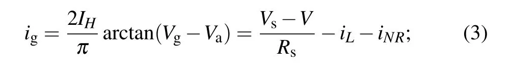
whereVgdenotes the output voltage whileVais the reverse cut-off voltage for the phototube,and the phototube is used as a voltage source when the linear resistorRsis selected with large resistance, and finite resistance forRsenables the activated phototube to excite the neural circuit as a current source.For further nonlinear analysis on this light-sensitive neural circuit,the following scale transformation is applied for Eq.(1):

and then the light-sensitive neuron (class 1) is represented as follows:
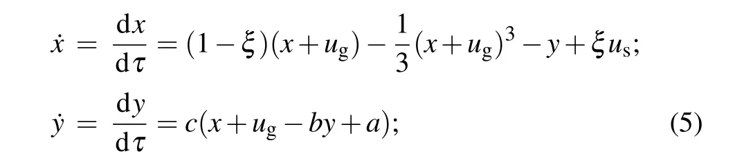
wherexandyrepresents the membrane potential as fast variable and the slow current as recovery variable, respectively.When the external stimulususand photovoltageugare selected with periodic forms,the functional neuron is driven to present a variety of firing modes. For simplicity, the exciting stimuli are given with the same angular frequency and diversity in amplitude as follows:

whereB1andB2define the amplitudes for the external forcing signals, and they can be regulated in practical way. As is known, two eyes are regulated to recognize the targets and objects, and the possible mechanism can be that two visual neurons are coupled for reaching synchronization. Therefore,two light-sensitive neural circuits are coupled via a resistor connection,and the connected circuits are plotted in Fig.2.

Fig. 2. Schematic diagram for two coupled light-sensitive neural circuits. The coupling channel is controlled by the linear resistor Rk,and the two identical circuits are driven by the same stimulus.
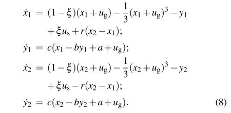
By the same way, the coupled neural circuits for Fig. 2 are described by
The coupling intensity is updated asr=ρ/Rk, and any changes in the resistance of the coupling channel will regulate the coupling intensity and consumption of Joule heat. For simplicity,the two phototubes are identical in the coupled circuits asug1=ug2=ug,us1=us2=us. Applying similar scale transformation for Eq. (7), and the two coupled neurons are described by
From dynamical viewpoint, the coupling channel can be tamed with appropriate intensity, and possible transition and stability of synchronization can be induced effectively. For two identical neurons, the same external stimulus and photocurrent enable distinct transition from phase synchronization to complete synchronization with the increase of coupling intensity. On the other hand,any diversity in the external stimulus or photovoltage will induce difference in the excitability,as a result, phase synchronization becomes available rather than complete synchronization approach.
When a phototube is connected to the induction coil in the branch circuit shown in Fig. 3, the induction current and induced electromotive force (IEF) will be controlled by the photocurrent,and then the output voltage from the capacitor is regulated for presenting different firing modes.

Fig.3. Case 2 Schematic diagram for the light-sensitive neural circuit(phototube connects to the inductor and constant voltage source in series). Vs, E, C, L, R, Rs and NR represent the external signal source,constant voltage source, capacitor, induction coil, linear resistors and nonlinear resistor,respectively.
By applying similar scale transformation for the variables and parameters in Eq.(9)and channel current across the same nonlinear resistor defined in Eq. (2), the dimensionless functional neuron(class 2)can be updated as follows:

As a result,two external stimuli can excite and inhibit the neural activities along different channels,and the firing modes are dependent on the balance between two kinds of channel currents completely. Similar to the coupling connection in Fig.3,the two light-sensitive neurons defined in Eqs.(9)and(10)can be connected via a resistor in Fig.4.
As a consequence, the coupled neural circuits for case 2 can be described by
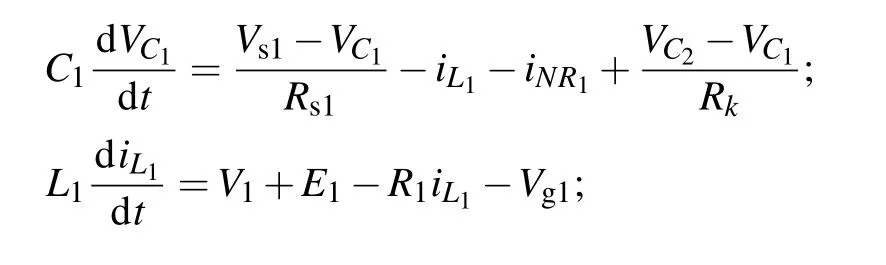


Fig. 4. Voltage coupling via resistor Rk for two light-sensitive neural circuits for case 2.
By applying the same scale transformation for the variables and parameters in the circuits equations in Eq.(11),and then the dimensionless neurons under electrical synapse coupling with coupling intensityr=ρ/Rkcan be described as follows:

Similar to case 1,the coupling channel can be adjusted to detect the occurrence and stability of phase synchronization and complete synchronization. For two identical neurons, we setug1=ug2=ug,us1=us2=usand they are driven by the same stimuli. In a numerical way, the following error function is defined to confirm whether complete synchronization can be induced:
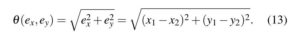
By applying an appropriate coupling intensity, two identical light-sensitive neurons can be tamed to reach complete synchronization and the error function in Eq. (13) can be decreased to zero within finite transient period. As is well known, the Joule heat consumed in the coupling channel via resistor connection is inevitable,and its continuous accumulation will have possible damage on the neural circuit.Within an average transient period,its energy across the coupling resistor can be estimated by

Furthermore, the consumption of Joule heat in the neurons coupled by electric synapse can be updated by applying scale transformation for Eq.(14)as follows:

Before reaching complete synchronization, the energy consumption along the coupling channel via resistor keeps active and the total Hamilton energy in each neuron (neural circuit)is against balance. When the coupling intensity is beyond the threshold, the consumption of Joule heat is terminated when complete synchronization is reached between two identical light-sensitive neurons. On the other hand,any diversity in the phototube and external stimulus (voltage source) can induce difference in excitability and parameter mismatch,realization of complete synchronization becomes unavailable except for phase synchronization and/or phase lock even the coupling intensity is increased greatly. As a result, energy balance becomes difficult between two neurons and energy is pumped along the coupling channel continuously. When the coupling intensity is below the threshold, the approach of phase synchronization becomes interesting and the phase series are often derived by using Hilbert transformation on the membrane potentials as follows:
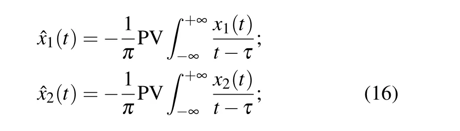
where the PV denotes the Cauchy integral and the phase series are obtained by

For phase lock stability,it requires the phase error function as follows:

where the integer numbersm,ncan be confirmed when the scale parameterεis about 10−5,and it predicts the occurrence of phase lock. At specific case, phase synchronization is stabilized atm=n=1 when the coupling channel is regulated with lower coupling intensity between two identical neurons.Phase lock can also be controlled between two non-identical neurons by further increasing the coupling intensity carefully.
3. Numerical results and discussion
In this section, the fourth order Runge–Kutta algorithm via MATLAB (ODE45) is used to find numerical solutions for isolated neuron model and coupled neurons with time steph=0.01,and the transient period for calculating is about 2000 time units. At first,we calculate the dynamics dependence on the angular frequency in the stimuli,and the bifurcation analysis,phase portraits are plotted in Fig.5.
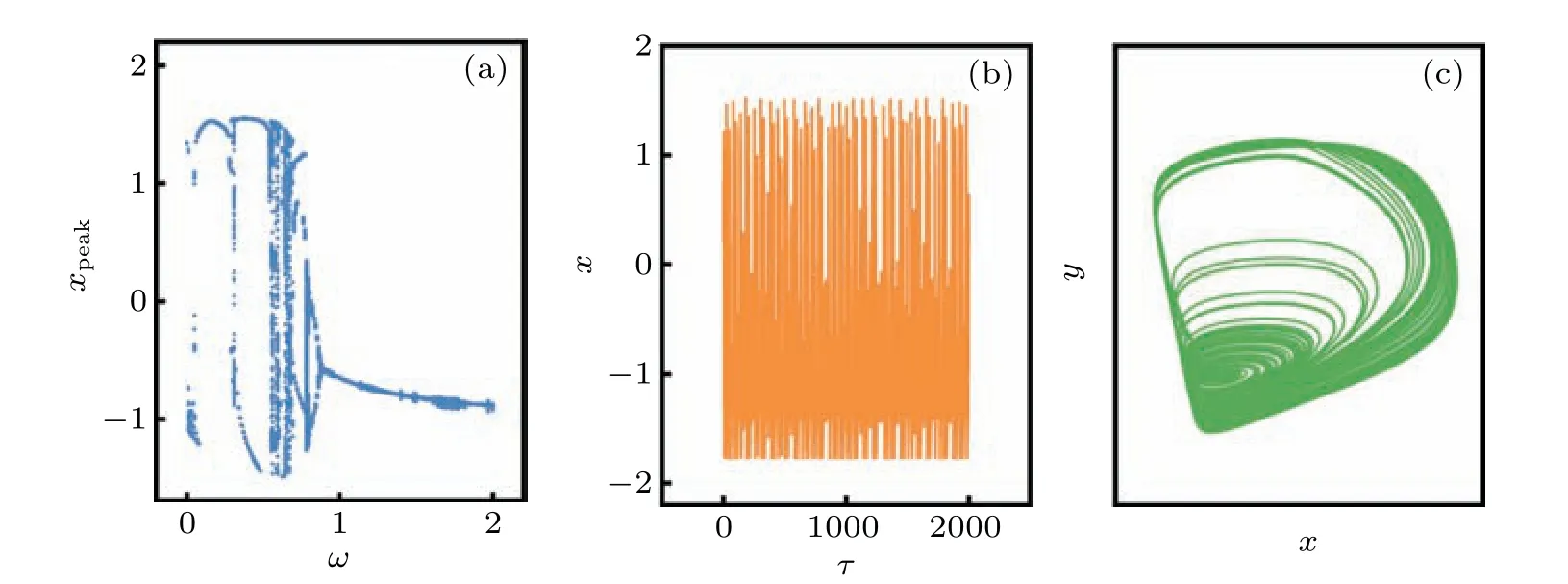
Fig.5. (a)Bifurcation diagram for peak value xpeak in the sampled time series for membrane potential x,(b)firing patterns in the membrane potential and (c) chaotic attractor. The parameters are fixed at ξ =0.175, ω =0.56, B1 =2.1, B2 =0.2, a=0.7, b=0.8, c=0.1, and the initial values are selected as(0.2,0.1).
That is, the isolated functional neuron can be induced from periodic firing to chaotic firing with increasing the angular frequency in the stimuli, and then chaotic attractor is formed. In addition,electric synapse coupling is switched on,and then the evolution of error function and conditional Lyapunov exponent spectrum are calculated by changing the coupling intensity carefully,and the results are plotted in Fig.6.

Fig.6. (a)Maximal value θmax in the error function and(b)Lyapunov exponents are calculated by changing the coupling intensity with time.The parameters for neuron in case 1 are fixed at ξ =0.175,ω =0.56,B1=2.1,B2=0.2,a=0.7,b=0.8,c=0.1,and the initial values are selected as(0.2,0.1,0.02,0.01).
When the coupling intensity is beyond the threshold 0.05,the two neurons driven by the same periodic stimuli will be stabilized in complete synchronization within finite transient period. In addition, the threshold of coupling intensity for reaching complete synchronization can also be estimated by calculating the largest Lyapunov exponent, or using saturation gain method.[55]That is,the careful increase of coupling intensity will induce the largest Lyapunov exponent become negative and the threshold of coupling intensity is confirmed.Indeed, the distribution of Lyapunov exponents in the functional neuron is related to the parameter regions, as a result,the threshold of coupling intensity for reaching complete synchronization becomes different when the intrinsic parameters are fixed at different values. For simplicity,two parameters(b,ξ) are changed and the largest Lyapunov exponent is calculated to discern the firing patterns in isolated neuron.
That is, when external stimuli are fixed, the intrinsic parameters (b,ξ) can be controlled to induce distinct transition from periodic firing to chaotic firing patterns. The attraction basin is also calculated within the region of the initial condition plane, and it indicates that the formation of the attractor is independent of the initial values. As a result,attractor’s attraction basin has no obvious vibration with the changing in the initial conditions. Extensive numerical results confirmed that any setting for the initial values will be effective to develop the same attractor in the phase space. Also, according to Fig. 6, appropriated coupling intensity can be applied to control the synchronization stability, e.g., complete synchronization is stabilized atr>0.05 by fixing the same parameter values in Fig.6,and the coupling intensity is adjusted to detect the occurrence of complete synchronization in Fig.8.

Fig. 7. (a) Distribution for the largest Lyapunov exponent is calculated with increasing the parameters(b, ξ)in the two-parameter space at ω=0.56,B1=2.1,B2=0.2,a=0.7,c=0.1;(b)local basins of attraction in two initial planes at ξ =0.175,ω=0.56,B1=2.1,B2=0.2,a=0.7,b=0.8,c=0.1. The snapshot is plotted in color scale.
It is confirmed that two identical neurons can be synchronized under electric synapse coupling when the coupling intensity is further increased. Furthermore, the consumption of Joule heat along the coupling channel is calculated in Fig. 9 by applying different coupling intensities.

Fig. 8. Evolution of error function is calculated by setting different coupling intensities. The parameters for neuron in case 1 are fixed at ξ =0.175,ω=0.56,B1=2.1,B2=0.2,a=0.7,b=0.8,c=0.1,and the initial values are selected as(0.2,0.1,0.02,0.01).

Fig.9. Joule heat consumed in the coupling channel via resistor under different coupling intensities. The parameters for neuron in case 1 are fixed at ξ =0.175, ω =0.56, B1 =2.1, B2 =0.2, a=0.7, b=0.8,c=0.1,and the initial values are selected as(0.2,0.1,0.02,0.01).
As confirmed in Fig. 9, the consumption of Joule heat is terminated completely when the coupling intensity is increased to stabilize complete synchronization. Indeed, when the coupling intensity is below the threshold,the approach of complete synchronization is blocked and phase lock is tamed in Figs.10–12.

Fig. 10. Phase error function is calculated by changing the coupling intensity for two bursting neurons (ω =0.0007, ω′ =0.008). For (a)r=0.0001; (b)r=0.001; (c)r=0.01; (d)r=0.02, and the parameters are fixed at ξ =0.175,B1=2.1,B2=0.2,a=0.7,b=0.8,c=0.1,and the initial values are selected as(0.2,0.1,0.2,0.1).
It is found that two bursting neurons cannot be controlled to reach phase lock in long period even when the coupling intensity is further increased. Then the frequency in the external stimuli is changed to estimate the phase lock between bursting neuron and chaotic neurons,and the results are plotted in Fig.11.

Fig. 11. Phase error function is calculated by changing the coupling intensity for bursting/spiking neurons (ω =0.01, ω′ =0.2). For (a)r =0.0015; (b) r =0.025; (c) r =0.035; (d) r =0.045, and the parameters are fixed at ξ =0.175, B1 =2.1, B2 =0.2, a=0.7, b=0.8,c=0.1,and the initial values are selected as(0.2,0.1,0.2,0.1).
That is,transition in short phase lock is induced with the increase of the coupling intensity below the threshold, and phase synchronization becomes difficult between spiking neuron and bursting neuron. We also investigated the phase lock between bursting/chaotic neurons,and the results are shown in Fig.12.

Fig. 12. Phase error function is calculated by changing the coupling intensity for bursting/chaotic neurons (ω =0.01, ω′ =0.56). For (a)r=0.0001;(b)r=0.001;(c)r=0.01;(d)r=0.02,and the parameters are fixed at ξ =0.175, B1 =2.1, B2 =0.2, a=0.7, b=0.8, c=0.1,and the initial values are selected as(0.2,0.1,0.2,0.1).
As confirmed in Fig.12,two chaotic/bursting neurons are coupled to reach stable phase lock with further increase of the coupling intensity. Furthermore, we discuss the dynamics and synchronization stability for neuron defined in case 2.In Fig.13,the external stimuli are adjusted in the angular frequency, the bifurcation analysis and phase portraits are plotted by changing the angular frequency of the external voltage source and voltage across the phototube.
When the light-sensitive neurons are driven by two external stimuli, increasing the angular frequency in the voltage sources will induce distinct transition from periodic friing to the chaotic friing patterns. For example,the neuron can present periodic friing atω=0.1 and then it is switched to chaotic friing atω=0.4. Furthermore, the same initial values (0.2, 0.1, 0.02, 0.01) are applied for the two neurons under electric synapse coupling, and then the evolution of error function and conditional Lyapunov exponent spectrum are calculated by changing the coupling intensity carefully, and the results are shown in Fig.14.

Fig.13. (a)Bifurcation diagram for peak value xpeak in the sampled time series for membrane potential x,(b)firing patterns in the membrane potential and(c)chaotic attractor. The parameters are fixed at ξ =0.175,ω=0.4,B1=0.8,B2=0.2,a=0.7,b=0.8,c=0.1,and the initial values are selected as(0.2,0.1).

Fig.14. (a)Maximal value θmax in the error function and(b)the Lyapunov exponent of coupling-system are calculated by changing the coupling intensity with time. The parameters for neuron in case 2 are fixed at ξ =0.175, ω =0.4, B1 =0.8, B2 =0.2, a=0.7, b=0.8, c=0.1,and the initial values are selected as(0.2,0.1,0.02,0.01).

Fig. 15. (a) Distribution for largest Lyapunov exponent is calculated with increasing the parameters (b, ξ) in the two-parameter space at ω =0.4, B1 =0.8, B2 =0.2, a=0.7, c=0.1; (b) local basins of attraction in two initial planes at ξ =0.175,ω=0.4,B1=0.8,B2=0.2,a=0.7,b=0.8,c=0.1. The snapshot is plotted in color scale.
For two identical neurons driven by the same stimuli,further increase of the coupling intensity can stabilize complete synchronization within finite transient period. As mentioned above,any changes in the intrinsic parameters will change the Lyapunov exponents and dynamics in the neuron,and thus the distribution of the largest Lyapunov exponent and attraction basin are calculated in the two-parameter space, and the results are shown in Fig.15.
That is, chaotic and periodic firing patterns can still be induced by setting appropriate value for parameters (b,ξ) in case of external stimuli. The coupling intensity is carefully adjusted to detect the synchronization stability between two neurons under electric synapse coupling, and the results are plotted in Fig.16.

Fig. 16. Evolution of error function is calculated by setting different coupling intensities. The parameters for neuron in case 2 are fixed at ξ =0.175, ω =0.4, B1 =0.8, B2 =0.2, and the initial values are selected as(0.2,0.1,0.02,0.01).

Fig. 17. Joule heat consumed in the coupling resistor under different coupling intensities. The parameters for neuron in case 2 are fixed at ξ =0.175,ω =0.4,B1=0.8,B2=0.2,a=0.7,b=0.8,c=0.1,and the initial values are selected as(0.2,0.1,0.02,0.01).
It is confirmed that two identical neurons can reach complete synchronization under electric synapse coupling when the coupling intensity is beyond 0.059. Comparing the results in Figs.14 and 16 with those in Figs.6 and 8,the threshold of coupling intensity for reaching complete synchronization between neurons (class 1) is some lower than the threshold for neurons (class 2) because the same photocurrent drives and changes the membrane potential directly and thus synchronization approach needs a lower coupling intensity. In addition, the energy consumption in the coupling channel is also calculated in Fig.17 by changing the coupling intensity carefully.

Fig. 18. Phase error function is calculated by changing the coupling intensity for two bursting neurons (ω =0.004, ω′ =0.003). For (a)r=0.0001;(b)r=0.001;(c)r=0.01;(d)r=0.025,and the parameters are fixed at ξ =0.175,B1=0.8,B2=0.2,a=0.7,b=0.8,c=0.1,and the initial values are selected as(0.2,0.1. 0.2,0.1).

Fig. 19. Phase error function is calculated by changing the coupling intensity for bursting/chaotic neurons (ω =0.003, ω′ =0.4). For (a)r=0.003; (b)r=0.008; (c)r=0.011; (d)r=0.02,and the parameters are fixed at ξ =0.175,B1=0.8,B2=0.2,a=0.7,b=0.8,c=0.1,and the initial values are selected as(0.2,0.1,0.2,0.1).

Fig.20. Phase error function is calculated by changing the coupling intensity for two chaotic neurons(ω=0.4,ω′=0.42). For(a)r=0.024;(b)r=0.025;(c)r=0.027;(d)r=0.02,and the parameters are fixed at ξ =0.175, B1 =0.8, B2 =0.2, a=0.7, b=0.8, c=0.1, and the initial values are selected as(0.2,0.1,0.2,0.1).

Fig.21. (a)Analog circuit implement for neuron in case 1;(b)chaotic attractor;(c)chaotic series for output voltage. V1=0.5 V,V3=0.6 V,V4=V5=V6=V8=0.73 V, fV3=110 Hz, fV4= fV8=106.4 Hz, fV5=139.8 Hz, fV6=92.7 Hz, fV1=60 Hz.
From Fig.17,it is demonstrated that the consumption of Joule heat is decreased to zero within finite transient period only by increasing the coupling intensity, otherwise, the coupling resistor keeps consumption of Joule heat in the coupling channel. By the same way, the coupling intensity is selected below the threshold for detecting possible phase lock between neurons with different firing modes,and the results are shown in Figs.18–20.
Similar to the phase lock in neurons for case 1,two bursting neurons can be adjusted in phase lock by changing the coupling intensity.The frequency in external stimuli is adjusted to trigger two different firing modes and phase lock is controlled in Fig.19.
Indeed,transition in phase lock is induced with short transient period,and phase lock becomes unstable for two bursting and chaotic neurons. The coupling intensity and forcing frequency are also tamed to check the stability in phase lock and the results are presented in Fig.20.
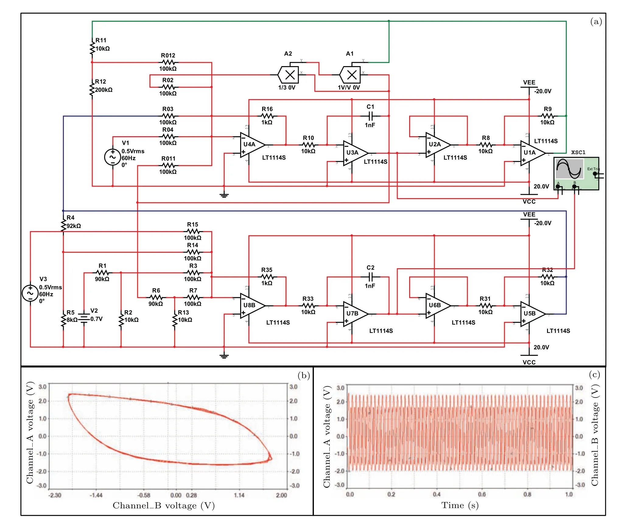
Fig.22. (a)Analog circuit implement for neuron in case 2;(b)periodic attractor;(c)periodic series for output voltage.V1=V3=0.5 V, fV1= fV3=60 Hz.
That is, for two chaotic neurons defined in case 2,phase lock becomes unstable even the coupling intensity is further increased, and it is some different from the results derived from neurons defined in case 1. From physical viewpoint,for case 1 that the phototube is connected to the capacitor,the external field energy in converted to electrical energy and then is injected into the capacitor for increasing its electric field energy directly, as a result, the membrane potential is regulated more effectively. On the other hand, for case 2 that the phototube is connected to the induction coil,the external field energy is used to against the blocking from constant voltage source and IEF,and then the channel current plays an important role in regulating the membrane potentials subsequently.Therefore,the dynamics and mode transition in the neural activities are also controlled by the connection position of the phototube to the branch circuit in the neural circuits.
Furthermore, it is interesting to reproduce the nonlinear response and mode selection in analog circuit,and equivalent analog circuits are designed by using Multisim platform. In Fig. 21, the neural circuit is built for the neuron defined in case 1 that the phototube is replaced by an equivalent voltage source.
By the same way,the analog circuit for the neuron defined in case 2 is built in Fig.22 and the sampled time series are used to show formation of chaotic attractors and chaotic firing patterns.
That is,the external stimuli can be adjusted to trigger different firing patterns and the stability of attractors is tamed effectively. We also present the coupled neural circuits for neurons defined in case 1 and the analog circuit under voltage coupling via resistor is shown in Fig.23.

Fig.23. Implement of coupled neural circuits for neurons defined in case 1.
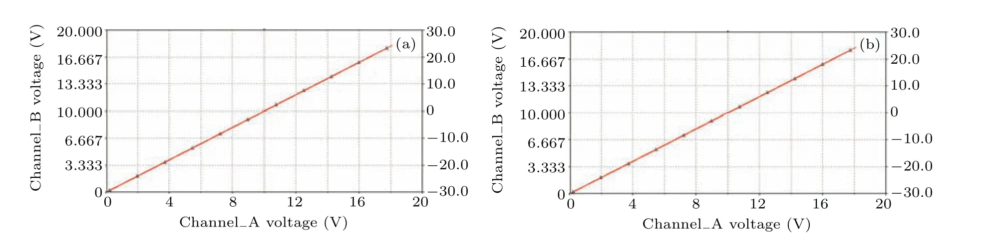
Fig. 24. Phase portraits for two coupled neural circuits, sampled time series for outputs voltage from two neural circuits are placed for the abscissa and ordinate. Panle(a)describes synchronization for neurons in case 1,panel(b)calculates the synchronization approach for neurons in case 2,and the coupling resistor Rk=100 kΩ.
In practical way,the resistance of coupling resistorRkcan be adjusted carefully,and then synchronization stability can be stabilized completely. In Fig.24,the phase portraits are calculated to confirm the occurrence of complete synchronization between two neural circuits and neurons (case 1, case 2) by applying different coupling intensities.
The experimental results confirm the consistence with the numerical results,and it indicates that two light-sensitive neurons and neural circuits can be controlled by external stimuli,and its synchronization stability can be effectively regulated in the coupling channel when electric synapse is activated.
In a summary, a phototube is incorporated into different branch circuits of a simple neural circuit, and its dependence of firing mode on and sensitivity to external illumination can show some difference. When the phototube is connected to the capacitor in series, the output voltage and membrane potential will be controlled by the external illumination and electromagnetic wave directly, and the neuron shows more sensitive to external stimulus. On the other hand, the connection of the phototube to induction coil in the branch circuit shows slow response because the photocurrent just adjusts the channel current of the induction coil by triggering continuous IEF, and then the membrane potential can be regulated indirectly. An electric synapse connection is effective to keep balance of energy from the two coupled neural circuits, and transient consumption of Joule heat along the coupling channel will be helpful to stabilize complete synchronization. The synchronization approach between two light-sensitive neurons also provides possible guidance and clues for knowing the synchronization processing between two visual neurons and artificial electric eyes. From dynamical viewpoint,numerical approach can be used to detect the suitable coupling intensity for stabilizing complete synchronization via bifurcation analysis,calculating the Lyapunov exponents and using saturation gain method.[56]Indeed, the application of master stability function[57–60]provides helpful guidance to discern the possibility of synchronization control in dynamical systems. In fact,it is more worth investigating the collective behaviors and synchronization stability in memristive neural networks[61–64]considering the effect of time delay and parameter perturbations by applying feasible schemes.
4. Open problems
As mentioned above, two kinds of light-sensitive neurons are proposed and the photocurrent has different impacts on the membrane potential and firing modes. In fact, the functional regions of brain contain a large number of neurons with specific biophysical functions, and the activation of body gaits relies on complete and enough cooperation between neurons in the same region and neurons from different regions of the brain. As reported in Ref. [29], a lightsensitive neuron can keep pace with a thermosensitive neuron under coupling via hybrid synapse,and it is interesting to discuss the synchronous firing patterns between two-layer networks, and the coupling channels between the light-sensitive neural network and thermosensitive network are adjusted carefully. When synapse coupling is suppressed, some neurons can be excited to reach resonance synchronization by capturing external field energy.[37,65]Therefore, it is interesting to discuss the resonance synchronization in a simple network composed of thermosensitive neuron,piezoelectric neuron,[37]this light-sensitive neuron,and magnetic-dependent neuron[16]under electromagnetic radiation and acoustic wave. Also, researchers can design a multi-layer network, and the local kinetics of the network can be described by different functional neurons in each layer. Within the same layer of the network,chemical synapse coupling, field coupling can be applied to explore the synchronization stability and pattern formation with/without heterogeneity and diversity in parameters, furthermore, stochastic disturbance and energy injection can be further considered. When static objects and a moving object are captured by the eyes,combined optical signals are encoded in the visual neurons and exact perception of the objects requires smart and quick cooperation among these visual neurons. For possible investigation, readers can explore the collective behaviors of these functional neurons (class 1 and/or class 2)in the network as follows:

where the subscript and superscriptiindicates the node position in this network,Drepresents the coupling intensity for synapse connection,ζ1(τ),ζ2(τ)denote the stochastic disturbance on membrane resulting from electric field and on channel current from magnetic field, respectively. The intensity of stochastic disturbance and synapse connection can be regulated carefully for detecting possible pattern formation and synchronization stability in the network and boundary condition can also be tamed as well.
5. Conclusions
In this paper, a phototube is coupled to a simple neural circuit and then it becomes sensitive to external light and electromagnetic wave within appropriate bands under photoelectric effect. However, the photocurrent across the phototube plays different regulation and exciting on the neural circuit.In fact, the neural circuit becomes more sensitive and dependent on external illumination and light when the phototube is connected to the capacitor in series directly because the photocurrent can change the membrane potential directly. When the phototube is connected to the induction coil in series along the branch circuit, the neural circuit (class 2 neuron) is also sensitive to external illumination but the mode transition in membrane potential is some slower than the neuron for class 1. Furthermore,electric synapse is tamed to realize complete synchronization between neural circuits and neurons, the targets are stabilized successfully when the coupling intensity is beyond the threshold. Before reaching complete synchronization,Joule heat is consumed in the coupling channel,and it is helpful to keep balance of energy between two neural circuits.These results provide possible clues to know the cooperation between visual neurons in the nervous system.
猜你喜欢
杂志排行
Chinese Physics B的其它文章
- Modeling the dynamics of firms’technological impact∗
- Sensitivity to external optical feedback of circular-side hexagonal resonator microcavity laser∗
- Controlling chaos and supressing chimeras in a fractional-order discrete phase-locked loop using impulse control∗
- Proton loss of inner radiation belt during geomagnetic storm of 2018 based on CSES satellite observation∗
- Embedding any desired number of coexisting attractors in memristive system∗
- Thermal and mechanical properties and micro-mechanism of SiO2/epoxy nanodielectrics∗