Generation of a large orbital angular momentum beam via an optical fiber winding around a curved path and its application∗
2021-10-28WeiHanTan谭维翰ChaoYingZhao赵超樱YiChaoMeng孟义朝andQiZhiGuo郭奇志
Wei-Han Tan(谭维翰) Chao-Ying Zhao(赵超樱) Yi-Chao Meng(孟义朝) and Qi-Zhi Guo(郭奇志)
1Department of Physics,Shanghai University,Shanghai 200444,China
2College of Science,Hangzhou Dianzi University,Hangzhou 310018,China
3State Key Laboratory of Quantum Optics and Quantum Optics Devices,Institute of Opto-Electronics,Shanxi University,Taiyuan 030006,China
4Institute of Fiber Optics,Shanghai University,Shanghai 200444,China
Keywords: fiber optics,orbital angular momentum(OAM),differential Fernet equation,Rayleigh criterion
1. Introduction
The generation of the optical beams with orbital angular momentum (OAM) have attracted much attention in optics communication and quantum key distribution. In these applications, we find that the OAM mode can be detected by the discrete “twisting” rate of helical phase. Up to now, the traditional methods of preparing OAM beam include rotating cylindrical lens, helical phase plates, and fiber[1–5]when the wave-front phase is changing and the principal ray is basically unchanged,[6–8]and it is difficult to obtain a large OAM modes. In order to solve the problem,we establish a theoretical framework on the condition that the principal ray is changing and the wave-front phase is basically unchanged.[9,10]The light emitted from the cylindrical spiral wave-guide can carry a high-order OAM modes.[11]In this paper,we achieve a large OAM modes in an optical fiber winding around a curved path of spiral body. We calculate the large OAM modes in the flowing coordinate system(α,β,γ). Applying the large OAM diffraction patterns,we can obtain a 12-bitencodes,and finally provide a high security information transfer system. At the same time, according to analyzing the zero OAM diffraction patterns, we find that our method can improve the spatial resolving power beyond the Rayleigh limiting.
The organization is as follows: The notation and parameters of the coordinate system,and types of winding around a curved path are presented in Section 2;subsequently,analytical solution is calculated in Section 3;numerical calculation of the OAM via an optical fiber winding around a curved path is given in Section 4;the diffraction patterns calculation and applications are given in Section 5; an experimental scheme for observation of a large OAM beam is proposed in Section 6;finally,the conclusion and discussion are given in Section 7.
2. The winding-types around the spiral body and the coordinate systems
The fiber winding around the circular cylinder body results in a spiral form,[9]but it does not mean that the circular cylinder body itself be a spiral form. The circular cones are depicted in Figs. 1(a)–1(c); and Figs. 1(d)–1(f) are the spiral curves of optical fiber around the circular cones.
In the static coordinate system,the curves as a function ofθcan be expressed by

wherea(θ)andbθdenote the radius and the axis of the circular cone function,respectively,andf(θ)is the winding function. As shown in Figs. 1(d)–1(f), we call the types of spiral curves, “Exponential”, “Gaussian”, and“Flower”, respectively:


where the constantsa0,l1>0, andncontrol the characteristic of circular cone;l2≥0 controls the winding-type.l2=0,l2> 0, andl2= ∞denote the homogeneous winding, inhomogeneous winding,and stop-winding,respectively.
As shown in Figs. 2(a) and 2(b), we adopt two coordinate systems in order to perform the following calculation,the first is static coordinate systemr=rxx+ryy+rzz,where the fixed unit vectors(x,y,z)are perpendicular to each other,and the second is flowing coordinate systemr=ξβ+ηγ+ζα,where the moving unit vectors (β,γ,α) are perpendicular to each other,which along a spiral curve of optical fiber as shown in Figs.1(d)–1(f).

Fig.1. Circular cones(a)–(c),and the spiral curves of optical fiber around the circular cones(d)–(f).
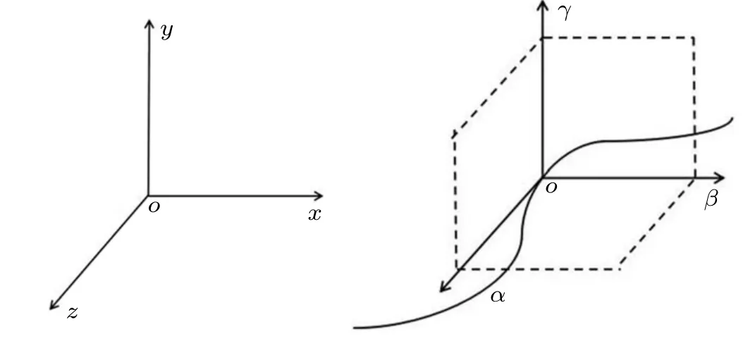
Fig.2. Static coordinate system(a)and flowing coordinate system(b).
3. Analytical solutions for the OAM
In generally, the curved path can be written by the static coordinate systemr=rxx+ryy+rzz. The path lengthscan be defined by
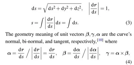
The moving unit vectors(α,β,γ)satisfy the Frenet equations

whereκ(s) andτ(s) are the curvature and the torsion of the curve,respectively.
In the static coordinate system,when curved path winding around the spiral body,Eq.(1)takes the following form:
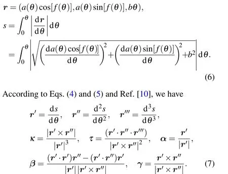
Using Eqs.(6)and(7),we can calculate the moving unit vectors(α,β,γ),and scalarκandτas a function ofθas

whereusatisfies the boundary condition|u|=0,whenρ ≥ρ0,whereρ0is the optical fiber radius. The solution ofy(ρ)can be written in terms of the Bessel function ofρ/ρ0as

4. Numerical calculations of the OAM
Figures 3(a) and 3(b) depict the three dimension spiral path around the “Exponential” curve andLα/ħ is a function ofθas shown in Figs.3(b1)–3(b3). We can find out:
(i) Homogeneous winding(see Figs.3(a1)–3(b1))is uniform, but the spiral path amplitude andLα/ħ gradually decrease to zero at the same time, which can not give a large OAM.
(ii) In-homogeneous winding (see Figs. 3(a2)–3(b2))gradually decreases to a straight line(see Fig.3(a2)),and theLα/ħ curve(see Fig.3(b2))drops simultaneously from a high value to a low gradually, which also can not generate a large OAM.
(iii) The two stages winding(see Figs.3(a3)–3(b3))consists of two parts.The first homogeneous winding begins fromθ=0 to 200,and theLα/ħ increases from 0 to 148. The second stopping winding begins fromθ=200 to 1000,theLα/ħ maintains at 148, and the curve of Figs. 3(a3) moves in the direction of the tangent direction gradually approaching to a straight line. More discussions are given in Section 7.
It is useful for us to obtain a high OAM modes when light beam propagates along a straight line. The continuity of curve atθ=200 will be proved in Appendix C.
From the above we can not come to the conclusion that the spiral path (see Figs. 3(b1) or 3(b2)) is not a valid path to obtain the large OAM modes. Because there are two kinds of optical fiber winding directions, one is the clockwise direction winding from right to left, and the other is the anticlockwise direction winding from left to right. From the zero OAM increasing to the maximum OAM, we adopt the anti-clockwise direction winding,and after reaching the maximum OAM, we adopt the clockwise direction winding. In the exponential type Eq.(2),the anti-clockwise winding functionfc(θ)=θ/(1+l2|θ|), and the clockwise winding functionfac(θ) =−θ/(1+l2|θ|). The numerical calculations of spiral path according to anti-clockwise direction before the maximum ofLα/ħ (the winding functionfc(θ)) and afterward according to clockwise direction (the winding functionfac(θ))are depicted in Figs.3(c1)–3(c3),and the corresponding large OAM are shown in Figs.3(d1)–3(d3),respectively.
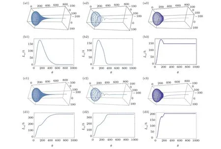
Fig.3.The three-dimensional spiral path around the exponential type Lα/ħ as a function of θ with parameters ka=5,kb=1,(a1),(b1) l1=0.015,l2=0,homogeneous winding;(a2),(b2)l1=0.015,l2=0.01,in-homogeneous winding;(a3),(b3)l1=0.015,θ =0−200,l2=0,homogeneous winding,θ =200–1000,l2=∞,stop-winding. (c1),(c2),(c3)and(d1),(d2),(d3)change the winding direction at the maxima of Lα/ħ.
In Figs. 4 and 5, we depict the three dimensional spiral curves withLα/ħ as a function ofθfor the Gaussian and the Flower types,respectively. The winding are homogeneousl2=0.
This curve tells us that we can obtain a large OAM modes easily.
One interesting thing is the Flower type OAM withLα/ħ as a periodic function ofθ, and the maximum and minimum locates nearly at two straight linesLα/ħ≈±60×θ,±100×θ,±250×θforn=1,3,5, respectively. The input light beam should be along the tangent direction near the positionθ ≈0 of Figs.5(b1)–5(b3). Figures 5(a1)and 5(a2)show clearly the low ends of the optical fiber,which is the position of the input beam.
The input light beam should be along the tangent direction near the positionθ ≈0 of Figs. 5(b1)–5(b3). Figures 5(a1) and 5(a2) show that the pointθ ≈0 locates at the milder of the optical fiber. It is a suitable input beam position,due toθ ≈0,Lα/ħ≈0,andd(Lα/ħ)/dθ=0. If we choose the end of the optical fiber as the input beam,due toθ=−10,andLα/ħ/=0, we must choose a point near the end and satisfying the conditionLα=0. Refer to Fig. 5, the points ofLα=0 areθ=−9.4,−9.9,−9.95 forn=1,3,5,respectively.
For the purpose of convenience of experimental realization, we give some explanations. In Figs. 1–3, the parameterkb0=1,yieldsrz=θλ0/2π,andδrz=δθλ0/2π. When the spiral path makes a circuit,δθ=2π, the distance between adjacent spiral coil satisfiesδrz=d=λ0. Hereλ0is the orbital wave length. As shown in Fig.1(b1),we setd=0.1 cm,θ=1000, then the total length of the spiral body equals torz=0.16 m and we havekzrz=θλ0/λ=θd/λ, whereλis the laser wave length. In the flowing coordinate system (see Eq. (15))kzrz=θd/λ →θl=−(ωt −kζζ). In general, the variableθis essential for theθlin the wave function Eq.(16),except a constant factord/λ.

Fig.4. The Gaussian type with parameters ka=100, kb=1, l1 =0.0005,l2=0: (a)three-dimensional curve,(b)Lα/ħ as a function of θ.

Fig.5. The flower type with parameters ka=25,kb=1,l2=0. (a1)n=1,(a2)n=3,(a3)n=5,three-dimensional curve;(b1)n=1,(b2)n=3,(b3)n=5,Lα/ħ as a function of θ;(c1)n=1,(c2)n=3,(c3)n=5,the flower type finding zero point curve.
5. Diffraction pattern calculations and applications
Before the diffraction pattern calculations, we need demarcate the diffraction modes in free space and the diffraction modes inside the optical fiber.


The underlying physics meaning will be discussed in Section 7.
With the purpose of observation of the diffraction patterns calculated in Fig.3(b1),the OAM regionν=0–53 as shown in Table 1.
The first group containsa1–a12diffraction patterns forθ=0–24 andν=0–30 (see Table 1), and the second group containsb1–b12diffraction patterns forθ=29–34.5 andν=42–53(see Table 1).
For simplification, the diffraction patterns shown in Figs.7(a)and 7(b)present only part of that listed in Table 1.
By utilizing the 12-bit(ai,bi,i=1–12)encoded diffraction patterns and the experimental observation of the OAM as a function of time(the temporal variation of diffraction patterns),the optical information transfer may be realized in principle. Combining the total 24 patterns,we have more different 12-bit encodes.

Table 1. The a1–a12 diffraction patterns for θ =0–24 and ν =0–30, the b1–b12 diffraction patterns for θ =29–34.5 and ν =42–53.

Fig. 6. (a1)–(a2) The diffraction pattern in free space ν =Lα/ħ=0;[12](b1)–(b2)inside the optical fiber(see Appendix B)ν=Lα/ħ=0,s00=2.3;(c1)–(c2)inside the optical fiber s016=49.5.

Fig.7(b). Part of the b1–b12 diffraction patterns(listed in Table 1)of optical fiber at the end of spiral body in Fig.3(b1).

Fig.7(a). Part of the a1–a12 diffraction patterns(listed in Table 1)of optical fiber at the end of spiral body in Fig.3(b1).
6. A thinking experimental scheme for observation of a large OAM temporal pulse
The diffraction patterns calculated in Figs. 6 and 7 are electric fields inside the optical fiber, which can not be observed directly. In order to observe these patterns, we must let it propagate out of the fiber and transfer a distancezarriving the screen. For this purpose and refer to Ref. [14], we propose a thinking experimental scheme for observation of a large OAM temporal pulse as shown in Fig.8,using the linear polarized laser as the input beam.

Fig. 8. The optical fiber winding is stopped at θ0 =388, ν =30, z=B=0.07 m,0.7 m.
The electric field of laser beam is incident from the leftside of circular cone enjoying the formE0(r,θ)=A0e−r2/w2,and after passing through the spiral curve winding the circular cone(see Fig.3(b3),the homogenous windingθ=0–θ0,and the stop windingθ>θ0),the electric field of large OAM spiral optical fiber(SOF)E0sof(r,θ)presents at the end of right-side of circular cone,then transferszdistance in free space to arrive the screen. We can calculate the diffraction patterns with the help of Collins formula[15]

In real calculation, we takeE0sof(r,θ)=a9,a12in Fig. 7(a).The parameters are listed in Table 2.
We can observe the following diffraction pattern in Fig.7(a).

Table 2. The parameters of the electric field of large OAM spiral optical fiber E0sof(r,θ)=a9,a12 in Fig.7(a)with the same ν and z.

Fig.9. The spiral optical fiber(SOF)modes a9, a12 (see Fig.7)propagate through a distance z=0.07 m,z=0.7 m and arrive at the diffraction screen,where ν denotes the OAM modes.
For reference, we remove the circular cone from Fig. 8 and let the laser beam incident directly to the diffraction screen with the sameνandz,and the traditional circular hole(CIH)diffraction patterns are also calculated

According to Ref. [16], the beam spot sizew(z), the radius of optical fiberρ0, the minimum beam spot sizew(0) =w0=ρ0=sν0/k. The diffraction patternsEsof(ρ,r,θ), andEcih(ρ,r,θ) on the screen are calculated as shown in Figs. 9,and 10, respectively. The SOF and CIH diffraction patterns present a quit different intensity distribution on the screen when we take the sameνandz.

Fig. 10. The circular hole (CIH) modes propagate through a distance z=0.07 m,z=0.7 m and arrive at the diffraction screen,where ν denotes the OAM modes.
7. Discussion and conclusion
In this paper, based on the differential Frenet equation and Einstein’s photon momentum assumption, we obtain an analytical solution for the OAM of ray propagating in an optical fiber with winding around a spiral body, then we proceed the numerical calculations of the OAM of the principal light and the diffraction patterns at different pointθcorresponding to different OAM. The diagrams of OAM depicted in Figs.3(b1)–3(b3)demonstrate that the necessary and sufficient conditions for an increase(or decrease)ofδ(Lα/ħ)/=0,area(θ)>0 and windingδθ/=0. In Figs. 3(b1) and 3(b2),we find out that whena(θ)→0,δ(Lα/ħ)→0. In Fig.3(b3),the winding stop point atθ=200,Lα/ħ=148. whenθ>200,δ(Lα/ħ)=0. In theory,[10]it is proved when curvatureκ(θ)=0, the curve degenerates to a straight line; when torsionτ(θ)=0, the curve is a plane curve; the necessary and sufficient condition of the curve being space curve isκ(θ)/=0,andτ(θ)/=0.The second stopping winding stage of Fig.3(a3)shows the path of fiber is a plane curve,the torsionτ(θ)=0,a simple algebra also givingrγ=rxηx+ryηy+rzηz=0,and using Eq.(13),it is easily to proveLα1/ħ=Lα2/ħ=0. This means in the second stage,there is no new contribution to the total OAM.
The results in Figs.3(c1)–3(c3)and 3(d1)–3(d3)supplement that of Figs. 3(a1)–3(a3) and 3(b1)–3(b3) by changing the winding direction from clockwise to anti-clockwise at the maxima ofLα/ħ,with the OAM maintaining a high vale,and the circular-cone approaching a straight line, in the limit ofθ →∞.
The calculated diffraction patterns provide a 12 bit OAMencoded ultrahigh-security information system. From the viewpoint of fundamental research,the OAM of principal ray winding around a spiral curve is a particle picture, while the OAM of LG beam is a wave picture. The connection between the two pictures is the Einstein’s assumption for the photon momentummds/dt=ħk. In the theoretical study of spiral curves, it includs “Exponential”, “Gaussian”, and “Flower”types, while in reality, the first and second type are easily to obtain a high OAM up to 103−5, and the third “Flower” type is very interesting, which has a periodic relation between the maximum and minimum of OAM output.

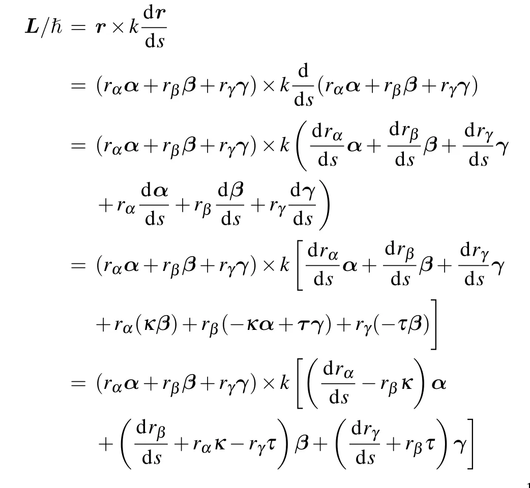
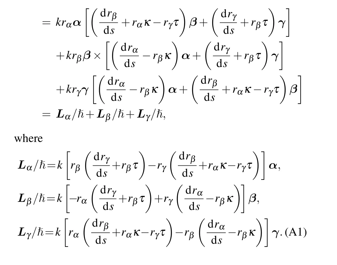
Appendix A: OAM calculation
Appendix B: Diffraction pattern integral
Using the solutionsu, the diffraction pattern can be calculated. Similar to the


where the acting forcesF1, andF2present the acting forces of the homogeneous winding stage and the stopping winding stage. Eq. (C1) shows that OAMLseems discontinuous due to the termεr×((F1+F2)+(F1−F2)Sgn[θ −θ0])ω−1,but in the limitε →0, and the acting force of the stopping winding stageF2=0, therefore, we have a continuous solutionL/ħ=∫θ00r×F1dθ(ħω)−1as a function ofθshown in Fig.3(b3)(θ0=200).
猜你喜欢
杂志排行
Chinese Physics B的其它文章
- Physical properties of relativistic electron beam during long-range propagation in space plasma environment∗
- Heterogeneous traffic flow modeling with drivers’timid and aggressive characteristics∗
- Optimized monogamy and polygamy inequalities for multipartite qubit entanglement∗
- CO2 emission control in new CM car-following model with feedback control of the optimal estimation of velocity difference under V2X environment∗
- Non-peripherally octaalkyl-substituted nickel phthalocyanines used as non-dopant hole transport materials in perovskite solar cells∗
- Dual mechanisms of Bcl-2 regulation in IP3-receptor-mediated Ca2+release: A computational study∗
