Effect of Coupled Torsional and Transverse Vibrations of the Marine Propulsion Shaft System
2021-09-10AkileNeHalilbeCongZhangOsmanAzmizsoysal
Akile Neşe Halilbeşe · Cong Zhang · Osman Azmi Özsoysal
Abstract In this study, the coupled torsional-transverse vibration of a propeller shaft system owing to the misalignment caused by the shaft rotation was investigated. The proposed numerical model is based on the modified version of the Jeffcott rotor model.The equation of motion describing the harmonic vibrations of the system was obtained using the Euler-Lagrange equations for the associated energy functional. Experiments considering different rotation speeds and axial loads acting on the propulsion shaft system were performed to verify the numerical model. The effects of system parameters such as shaft length and diameter, stiffness and damping coefficients, and cross-section eccentricity were also studied. The cross-section eccentricity increased the displacement response, yet coupled vibrations were not initially observed. With the increase in the eccentricity, the interaction between two vibration modes became apparent, and the agreement between numerical predictions and experimental measurements improved. Given the results, the modified version of the Jeffcott rotor model can represent the coupled torsional-transverse vibration of propulsion shaft systems.
Keywords Coupled torsional-transverse vibrations · Forced vibrations · Marine propulsion shaft system · Cross-section eccentricity · Jeffcott rotor · Coupled vibration in rotor system
1 Introduction
Understanding the effects of the single and coupled vibration modes in a ship, including torsional, longitudinal, and transverse vibrations of the propeller shaft, is important in the shipbuilding industry for the safe operation of the ship.Single and coupled vibration modes induce fatigue, fracture, and tribological issues on the overall shaft system. To avoid these structural problems, studies have been performed especially on torsional vibration and coupled longitudinaltorsional vibrations; however, studies on coupled torsionaltransverse vibrations are not sufficient.
The coupled torsional-transverse vibration results in imbalances caused by the propeller rotation or the mass of the shaft components. Owing to excessive torsional-transverse vibrations caused by unbalanced loads in the shaft system, various secondary structural failures such as rotor instability and bearing damage may occur (Murawski 2005; Rao et al. 2003; Shi et al. 2010). Thus, maintaining the integrity of the rotor-bearing system is an important safety concern.Consequently, the topic of coupled vibration has attracted much attention lately in the shipbuilding industry (Chahr-Eddine and Yassine 2014; Huang et al. 2017; Murawski 2004; Qu et al. 2017; Yang et al. 2014; Zhang et al. 2014).The significant imbalance may cause several issues related to structurasl mechanics, and coupled torsional-transverse vibration must be studied in depth. However, the number of studies in coupled torsional-transverse vibration regarding the shipbuilding industry is limited, with most of the studies focusing on aerospace engineering.
In their works, Friswell et al. (2010) and Tiwari (2017)provided a basic description of rotor dynamics and examined simple models with modern analysis methods. Using Lagrangian dynamics, Al-Bedoor (2001) and Mohiuddin and Khulief (1999) proposed a dynamic model of a rotorbearing system, considering gyroscopic effects and the inertia coupling between bending and twisting deformations.He et al. (2017) showed the dynamic characteristics of a crane system based on Hamilton’s principle under transverse and longitudinal disturbances. He et al. (2020) derived the governing equations and the boundary conditions of wings through Hamilton’s principle to achieve a rigid-flexible wing under bending and twisting deflection. In addition, Han et al.(2017) and Hong et al. (2020) studied a rotor system with a dynamic model in which the rotor disk is placed in the middle of a massless elastic shaft. The equation of motion was obtained through Lagrangian dynamics for lateral-torsional vibrations. Han et al. (2017) derived the equation of motion by assuming that the diesel engine drive system could be approached as a simple rotor model such as a Jeffcott rotor.Hashemi and Richard (2000) used the finite element method to model a bending-twisting beam. Moreover, Han and Lee(2019) and Yuan et al. (2007) numerically modeled vibrations caused by lateral and torsional forces by comparing the shaft system to the Jeffcott rotor system at three degrees of freedom. Also, Das et al. (2011) modeled a flexible rotor shaft system subjected to coupled bending and twisting with a shaft and a disk shifted away from the midpoint of the shaft. Most recently, Huang et al. (2019) considered that the propeller shaft is equivalent to a cantilever beam. The authors numerically solved a nonlinear model using a highorder Runga-Kutta method and verified the results through experiments performed at different rotational speeds. As seen from the above studies, the Jeffcott rotor, with the disk located at the midpoint of the massless shaft, is a common model for coupled torsional-transverse vibrations. In addition to these studies, research has also been conducted for the early detection of cracks that may occur in the rotor system because of vibrations. Papadopoulos (2008) presented different methods to enable the early detection of transverse cracks in the rotor system. Gayen et al. (2017) gave the finite element formulation of a shaft with multiple cracks to study the effects of transverse vibration in a rotor-bearing system.Moreover, Gayen et al. (2018) used finite element analysis to study the free vibration of the cracked shaft and compared the effect of multiple parameters on natural frequencies. Also, Gayen et al. (2019) improved the finite element formulations to analyze transverse cracks that occurred on a functionally graded shaft.
In the current study, a new numerical model based on a modified version of the Jeffcott rotor model is proposed to predict the dynamic behavior of the shaft system. The equation of the motion of the shaft is obtained considering the cross-section eccentricity, which may result from the shaft excessive vibrations. Typically, the increase in response is erroneously associated with the coupled vibrations of the system. However, stiffness coefficients were investigated in detail, and such a coupling was not observed. Accordingly,a new coefficient is proposed to describe the cross-section eccentricity. Experimental verifications are provided for different rotational speeds. To comprehensively assess the coupled torsional-transverse vibrations, this paper also investigates the effect of the system parameters and presents response amplitudes for different conditions. It was found that the modified version of the Jeffcott Rotor model accurately represents the coupled torsional-transverse vibrations of the propulsion shaft system.
2 Methodology and Numerical Model
The coupled torsional-transverse vibrations of rotor systems are commonly modeled using a Jeffcott rotor model, which has a massless shaft and a disk of massmlocated in the middle of the shaft. In this study, while the experimental setup was modeled numerically, a loading system instead of a propeller was attached to the end of the shaft, and the shaft movement is only provided by an electric motor that enables the shaft to rotate at certain speeds. Thus, the shaft was modeled with three degrees of freedom, as shown in Figure 1 (Han and Lee 2019).The shaft can be subjected to both torsional and transverse deformations. Here the mass center of the shaft is relocated with a distancee, andO′is the new location of the mass center, due to the acting forces. The shaft speed is given asω, andθrepresents the torsional displacement, andtdenotes time. Figure 1 shows the deformed configuration in a particular state. The governing equation of the system is obtained using Lagrangian dynamics. The kinetic energy of the shaft is given as Eq. (1):

Figure 1 Unbalanced shaft model

wherexcandycare the new positions of the mass center;their relationships withx,yare given as

whereeis the cross-section eccentricity of the system due to the external forces. Substituting the expressions of Eq. (2)into Eq. (1) gives the expression of the shaft kinetic energy:

In addition, the potential energy of the system is defined as

Similarly, the dissipation energy of the shaft system is presented as

wherekx,ky, andkθare the stiffness coefficients, andcx,cy, andcθare the damping coefficients in the torsional and transverse directions, respectively. The equations of motion for the shaft system are obtained by substituting the expressions of kinetic energy, potential energy, and dissipation energy in Lagrange’s equation:
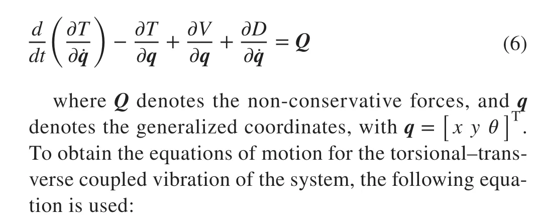

In Eq. (7), the torsional acceleration termsme¨θsin(ωt+θ)andme¨θcos(ωt+θ) are also found in the equations of transverse motions, while the transverse acceleration termsme¨xsin(ωt+θ) andme¨ycos(ωt+θ) are found in the equation of torsional motion. As a result, the transverse vibration interacts with torsional vibration through the inertia terms of the equations, this interaction is brought by the mass of the unbalanced loads. Moreover, the equations of motion of the unbalanced rotor system end up being nonlinear when the coupling of lateral vibration and torsional vibration is considered.
Usually, the torsional displacements in most rotor systems are small, and they are to be approximated based on the main term of their particular developments. Under this supposition, the accompanying relations are utilized. Generally, the amplitude of torsional vibration in most rotor systems is little,permitting sinθand cosθto be approximated based on the first term of their respective Taylor series expansions. Assuming this, the relations below are utilized (Hong et al. 2020):

Equation (9) is obtained by ignoring the unknown higherorder terms in Eq. (7) and adopting the assumptions in Eq. (8):
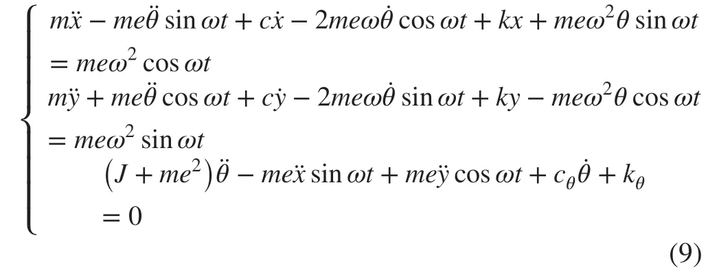
The coupled torsional-transverse equation of motion presented in Eq. (9) can be rewritten in the matrix form as shown in Eq. (10):

Equation (10) demonstrates that the cross-section eccentricity is the cause of the coupled torsional-transverse vibrations and therefore a fundamental element of the vibrations.The vertical and horizontal vibrations are observed to be unconnected to the torsional vibration, with the case ofe=0. To continue the coupled vibration calculations, the cross-section eccentricity is taken as 0.001 (Hua et al. 2017;Huang et al. 2017; Hong et al. 2020). The parameters used in the simulation are summarized in Table 1.

Table 1 Parameters of the propulsion shaft system
The external forces and torsional torque on the shaft are given asFx(t)=Fx0sin(ωt),Fy(t)=Fy0sin(ωt) andMθ(t)=Mθ0sin(ωt). Here,Fx0,Fy0,Mθ0are external forces measured from tail shaft, and they have different amplitudes at different rotational speeds.
To verify the numerical estimations, the coupled torsional-transverse vibration of the shaft system was experimentally investigated. Figure 2 presents the installation of the experimental setup. The experimental setup comprised of a loading system that represents the propeller which is located at end of the tail shaft, bearings to prevent movements, an electric motor as a marine engine at the other end of the shaft, a foundation to mount the whole plants, and a base frequency converter. Although the experimental setup included disks attached to the shaft that can be used in the numerical modeling of the crankshaft, in the present study, the disks are disregarded in the numerical modeling since the inertia torque and inertia of the disks are relatively small compared with those of the shaft.
There were two intermediate bearings to support the intermediate shafts and another stern bearing to support the tail shaft. Figure 3 presents measurement points where the sensors transmitting the analog signals were located.
The torsional and transverse vibration signals were recorded simultaneously along the shaft. The signal of the tail shaft was measured, and the shaft speed was checked using a laser torsional vibration meter (B&K MM0071 sensor and 2523 laser)(Figure 3). Additionally, measurements for the vertical and horizontal displacements of the tail shaft were conducted using the eddy current sensors (ZA-210803), as given in Figure 3. In this particular case, for the test, two measurement points of the tail shaft were selected for transverse vibration. Possible errors due to the vibration were reduced by fixing the sensor position.
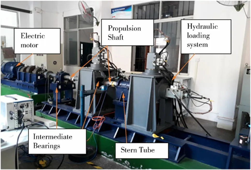
Figure 2 Experimental setup of the propulsion shaft system

Figure 3 Measurement point layout for the shaft. a vertical, b horizontal, c torsional
Transverse loads were exposed to a hydraulic system. A strain gauge positioned on the tail shaft was used to measure the torque produced by the transverse forces (Figure 4).Although the shaft speed values were determined from 100 to 190 in 30 increments and frequencies and amplitudes for the shaft coupled vibrations were recorded for each speed,the measurements and results presented in Sect. 4 are only for 100 r/min. The amplitudes of each transverse force applied and the corresponding torque were 300 kN and 0.06 N·m,respectively, for 100 r/min. Given that the test apparatus only permitted axial and transversal loadings, the torsional stress could not be directly obtained; nevertheless, torque values were obtained from the measured transverse stresses. The transverse stresses were collected for the transverse forces applied with regard to the displacements of the loading system. The applied displacements, measured torque, and transverse force amplitudes are provided in Table 2.
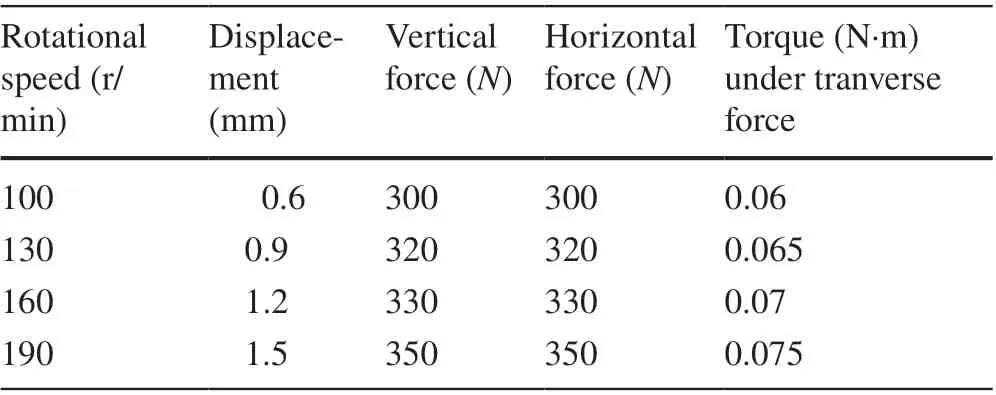
Table 2 Torque and transverse force values for considered rotational speeds
3 Numerical Model Verification
To obtain steady results, for each speed, the simulation time was taken as 1 min in the experiment. The initial conditions were taken asx0=y0=θ0=0, and the simulation time was applied as 10 s. The results tended to be steady in this period. The second half of the simulation time interval was used to show the numerical results.
The displacement values and frequency responses obtained with the numerical model in three directions are compared with the measurements. The results are given in Figures 5, 6, and 7 for 100 r/min shaft speed.

Figure 4 Hydraulic loading system and torque measurement point

Figure 5 Vertical displacement results a at 100 r/min, b between 0 and 5 Hz
Figure 5 indicates the displacements in the vertical direction for the experimental system and the numerical model at 100 r/min. While the vertical displacement was 3.292 × 10⁻⁴m at 1.541 Hz in the experiment, the numerical result was 2.941 ×10⁻⁴m at 1.648 Hz. In the graph given in Figure 5(a), the time step was kept the same as the experiment data to avoid errors in the comparisons with the experimental results; thus, even though the maximum displacements occurred before 5 Hz, the frequency range continued up to 500 Hz. The vertical displacement obtained from the numerical model was lower than that obtained from the experimental data. However, the frequency values corresponding to the maximum displacements were similar between the two models, despite the margin of error; this indicates that the numerical model yielded results similar to the experimental data. Figure 6 shows the displacements in horizontal vibration obtained from the experimental system and the numerical model at 100 r/min. While the vertical displacement was 3.979× 10⁻⁴m at 1.542 Hz for the experimental system, the numerical model result was 3.068 ×10⁻⁴m at 1.648 Hz.Figure 7 reveals that the torsional angles were 2.603 ×10⁻⁷rad at 1.542 and 2.307 ×10⁻⁷rad at 1.648 Hz for the experimental system and the numerical model at 100 r/min, respectively. Figures 5, 6, and 7 show that the test results were higher than numerical predictions, owing to the imperfection of theoretical models.

Figure 6 Horizontal displacements results a at 100 r/min, b between 0 and 5 Hz
3.1 Verification at Various Speed Ranges
Figures 8 and 9 indicate the difference in coupled torsional-transverse vibration between the experimental system and numerical models under increasing rotational speeds. This section evaluates the validity of the numerical method by considering the error margins of the experiment at different shaft speed values.
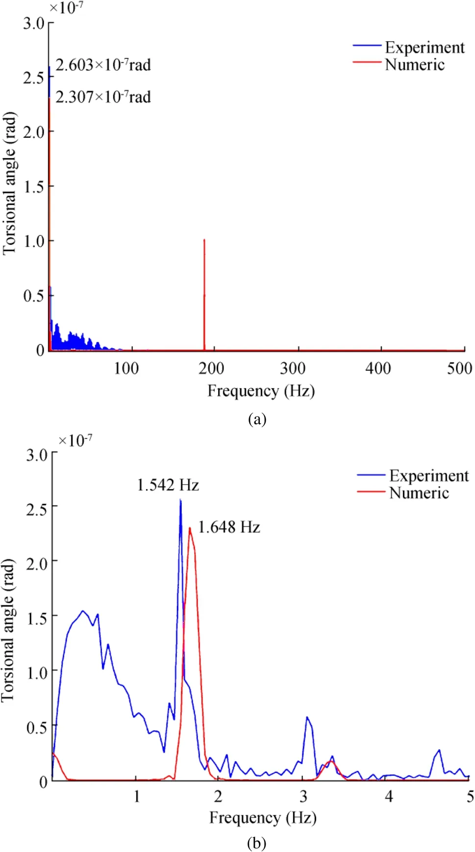
Figure 7 Torsional angle results a at 100 r/min, b between 0 and 5 Hz

Figure 8 Numerical results between 100 and 190 r/min. a Vertical, b horizontal, c torsional
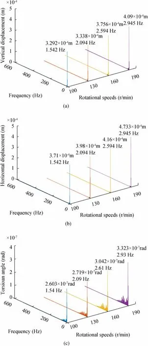
Figure 9 Experimental results between 100 and 190 r/min. a Vertical,b horizontal, c torsional
The torsional angle and transverse displacement of all numerical models were lower than the experimental data,and the error margins were similar for each rotational speed.In addition, the slopes of curves in the image are similar despite the error margin, indicating that the numerical models yielded a good correlation with the experimental data.
4 Discussion of Parameter Effect
The validity of the numerical model has been proved with the maximum displacement and forced vibration frequency at different shaft speed values. The main terms of the numerical model are the coupling effect, propeller shaft length and diameter ratio, stiffness and damping coefficients, and crosssection eccentricity. Thus, the influence of the above impact factors on the coupled vibration was studied to observe the vibration behavior of the model in detail at 100 r/min shaft speed. Transient solutions were obtained for each situation,and figures were created according to the maximum displacement values.
4.1 Coupling Effect
In Table 3, torsional and transverse vibration amplitudes are given for coupled and uncoupled vibration forms. When the differences between the three directions were examined, it was seen that the coupled effect had an impact only on transverse displacement. Comparing the vertical and horizontal directions, the coupling has an impact of approximately 0.1% and 4.4%, respectively; thus, the coupled vibration had a more effect on the horizontal axis.

Table 3 Coupling effect on three axis
4.2 Effect of Length and Diameter Ratio
The shaft length and diameter values are effective to define the stiffness and damping coefficient values and the mass and moment of inertia on the coupled torsional-transverse vibration. To examine the effect of the length change, the diameter value was kept constant, and the shaft length was multiplied by 0.8, 0.9, 1, 1.1, and 1.2. The torsional and transverse displacements varied with the length ratio (Figure 10), and all three axes were similarly affected.
Figure 11 depicts the variation in the vibration amplitudes in the three axes with the shaft diameter. To examine the effect of diameter change, the length was kept constant, and the shaft diameter was multiplied by 0.8, 0.9, 1, 1.1, and 1.2. The variation of the vibration amplitudes was directly proportional to the change in the shaft length but inversely proportional to the change in the shaft diameter. The shaft diameter is an important factor influencing the bending and twisting stiffness; thus, they are more currently effective onthe displacement values, and displacement values are not directly related to the shaft diameter.

Figure 10 Displacements for different shaft lengths

Figure 11 Displacements for different shaft diameters
4.3 Effect of Stiffness and Damping Coefficient Ratio
Stiffness and damping coefficients are important factors in shaft system optimization. In this study, these two values were first defined on the basis of bearings. However, to observe the effect of these factors on coupled torsional-transverse vibrations, the stiffness and damping coefficient were changed at a certain ratio while the other values were kept constant.
Figure 12 presents the displacement values corresponding to different damping coefficients under a constant stiff-ness coefficient and 100 r/min shaft speed. In the numerical model, the damping coefficients in the three axes given bydx,dy,dθhad no effect on the vibration; thus, the coeffi-cients are given with the same symboldon thex-axis. The damping coefficient did not have an observable effect on the system because of the rather small coefficient values.
The vibration amplitudes due to different rates of transverse stiffness coefficient values are given in Figure 13.While the transverse displacement decreased with the increase in coefficients, there was no change in the torsional angle. Figure 14 shows the vibration amplitude response to the change in the torsional stiffness coefficient. While the torsional angle decreased with the increase in the coeffi-cient, there was no change in the transverse displacement.Figures 13 and 14 indicate that the torsional and transverse directions do not interact. To reveal the causes of the lack of interaction between two vibration type, displacements at the different cross-section eccentricity values were investigated(Figure 15).
4.4 Effect of Eccentricity of Cross-Section Coefficient Ratio
Figure 15 presents the displacement values at different crosssection eccentricity values. At the cross-section eccentricity of 0.001, the vertical and horizontal axes interacted, but the effect on the torsional angle was too small to be seen. The coupled vibration effect disappeared with a decrease in theevalue, except at the first stage of numerical calculations.However, with the increase in the cross-section eccentricity,the displacements significantly increased, demonstrated by the occurrence of more interactions between two vibration forms.
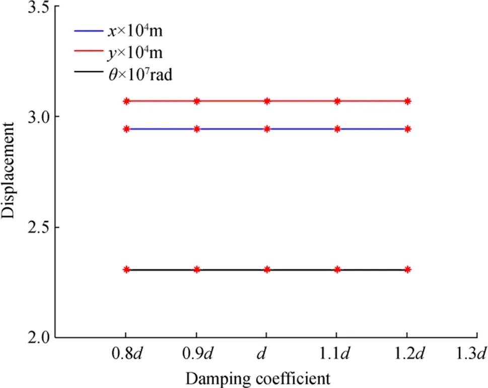
Figure 12 Displacements for different damping coefficients
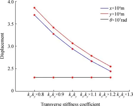
Figure 13 Displacements for different transverse stiffness coefficients

Figure 14 Displacements for different torsional stiffness coefficients

Figure 15 Displacements at different cross-section eccentricities
When the cross-section eccentricity value wase=0.005,the displacement values were 3.009 ×10⁻⁴m in the vertical direction, 3.59 ×10⁻⁴m in the horizontal direction, and 2.409 ×10⁻⁷rad in the torsional direction. A comparison of these displacement values with the experimental results shows that the error margin decreased and the interaction between vibration forms increased compared with the case undere=0.001. Consequently, the coupled vibration effect was not seen between the torsional and transverse directions at anyevalue selected from the references, and it is important to correctly determine the eccentricity of the cross-section coefficient value in the design stage.
5 Conclusions
In this study, a shaft model was subjected to torque and transverse excitation forces, and the dynamic behavior of the system with coupled torsional-transverse vibration was observed. The displacements and frequency response of the system for single and coupled vibrations were comprehensively investigated, and the major conclusions are as follows:
(1) Under the low eccentricity value, except at the first stage, no coupling effect was observed on the torsional angle; the coupling effect was mostly between the horizontal and vertical vibrations. However, with an increase in the eccentricity, the coupling effect was more significant, and vibration forms interacted.Additionally, the margin of error with the experiment decreased.
(2) The displacement amplitudes increased in three directions with an increase in the shaft length and decreased with an increase in diameter. The displacements were directly proportional to the shaft length ratio and changed at an equivalent rate but inversely proportional to the shaft diameter; the effect of the diameter was larger, and it was not directly associated with the displacement ratio.
(3) The change in damping coefficient had no effect on the system because of the rather small damping value.Moreover, the change in the transverse stiffness values did not affect the torsional angle, and the change in torsional stiffness values did not affect the transverse displacement values. Thus, an increase in the displacement values does not always indicate that coupled vibration occurred between the vibration forms, and it is important to accurately define the cross-section eccentricity coefficient value.
In future work, the coupling under added mass and hydrodynamic damping coefficients due to the propeller will be considered for the coupled vibration of the marine propeller shaft system. In addition, the fatigue, breakage, and tribological problems on the bearings and the poor performance and failure of the shaft system due to the coupled vibration will be examined.
AcknowledgementsThe authors thank Professor Xinping Yan, Dr.Cong Zhang, and Dr. Qianwen Huang at Wuhan University of Technology for their valuable support and guidance during the corresponding author’s academic visit to China. The corresponding author also thanks Asst. Prof. Bahadır Uğurlu and Ress. Ass. Ismail Kahraman from Istanbul Technical University for their support and patience.
FundingThis investigation was supported by the Scientific and Technological Research Council of Turkey (TUBITAK) 2214-A International Doctoral Research Fellowship Programme, while experiments were performed at the Wuhan University of Technology.
Open AccessThis article is licensed under a Creative Commons Attribution 4.0 International License, which permits use, sharing, adaptation, distribution and reproduction in any medium or format, as long as you give appropriate credit to the original author(s) and the source,provide a link to the Creative Commons licence, and indicate if changes were made. The images or other third party material in this article are included in the article’s Creative Commons licence, unless indicated otherwise in a credit line to the material. If material is not included in the article’s Creative Commons licence and your intended use is not permitted by statutory regulation or exceeds the permitted use, you will need to obtain permission directly from the copyright holder. To view a copy of this licence, visit http://creativecommons.org/licenses/by/4.0/.
杂志排行
Journal of Marine Science and Application的其它文章
- Analysis of Wave Energy Resources Around the Saint Martin Island in Bangladesh
- Reliability Analysis Method of a Control System for Subsea All-Electric Christmas Tree
- Topside Axial Bearing Wear Under the Eccentric Load of a Single-Anchor Leg Mooring System in Bohai Bay
- Fire Risk Quantitative Assessment of Offshore Supported Platform
- Fast Tool for Structural Monitoring of a Pier After Impact of a Very Large Vessel Using Ambient Vibration Analysis
- Numerical Investigation of Sloshing Under Roll Excitation at Shallow Liquid Depths and the Effect of Baffles
