Reliability Analysis Method of a Control System for Subsea All-Electric Christmas Tree
2021-09-10PengLiuQianqianChenChaoZhengGuofaSun
Peng Liu·Qianqian Chen·Chao Zheng·Guofa Sun
Abstract The subsea all-electric Christmas tree(XT)is a key equipment in subsea production systems.Once it fails,the marine environment will be seriously polluted.Therefore,strict reliability analysis and measures to improve reliability must be performed before a subsea all-electric XT is launched;such measures are crucial to subsea safe production.A fault-tolerant control system was developed in this paper to improve the reliability of XT.A dual-factor degradation model for electrical control system components was proposed to improve the evaluation accuracy, and the reliability of the control system was analyzed based on the Markov model. The influences of the common cause failure and the failure rate in key components on the reliability and availability of the control system were studied. The impacts of mean time to repair and incomplete repair strategy on the availability of the control system were also investigated. Research results show the key factors that affect system reliability,and a specific method to improve the reliability and availability of the control system was given.This reliability analysis method for the control system could be applied to general all-electric subsea control systems to guide their safe production.
Keywords Subsea all-electric Christmas tree .Control system .Reliability analysis .Safe production .Dual-factor degradation model .Markov model
1 Introduction
Deyab et al. (2018) identified that offshore oil and gas processing equipment operating in harsh environments poses a high risk, which is further increased by harsh environments.Process safety, risk analysis, and reliability evaluation have paramount significance in modern process industries for preventing fatalities and asset and reputation losses caused by an accident(Cai et al.2019,Wang et al.2019c,Liu et al.2020).Subsea all-electric XTs are critical pieces of equipment in subsea production system(Liu et al.2019a,b).The control system of subsea all-electric Christmas trees(XT)is crucial to ensure the safe production of the equipment. Once a failure occurs,the equipment loses control and will have unimaginable consequences.When an oil spill occurs,the control system will fail to shut down the equipment, thereby causing serious environmental pollution. Leaked oil and gas floating on the sea surface are very likely to cause fire and other safety accidents.Therefore,the reliability of the subsea XT is crucial to ensure the safe production of the subsea system (Artana et al.2018).
Research on subsea all-electric production system is a current development trend and has unmatched advantages. The all-electric system involves a large number of electronic components; therefore, the theory and technology for reliability evaluation of all-electric control systems have become a hot research topic (Abaei et al. 2018). Reliability evaluation enables the identification of problems at different life cycle stages of a system or equipment. Even certified and tested equipment may experience problems during operation because of incorrect installation,operating environment,operator error,or lack of maintenance(Bitanov 2015;Wang et al.2020). More importantly, once subsea equipment has been installed, it must be transported to shore for maintenance and repair,which involves considerable financial and material resources.The best way to avoid such large maintenance costs is to improve the reliability of subsea equipment by performing a reliability evaluation before the equipment is launched.Moreover,a reliability evaluation guides the maintenance for engineering staff.
Wanvik, a researcher at the Norwegian University of Science and Technology (Wanvik 2015), identified that oil and gas development in the Arctic is an ongoing process.Subsea XT systems are the only viable equipment that can be utilized in this area because of the presence of ice and icebergs.The Arctic ecosystem is fragile,and oil spills in this area can have irreversible effects; therefore, highly reliable and safe subsea XT systems are required. Safe and reliable subsea production systems will become increasingly important. Chess Subsea Engineering, a world-renowned marine technology service company, developed a reliability model of the subsea XT and its control system over an 8-week period from January 2016 to March 2016 and subsequently performed a reliability evaluation of the subsea XT. From this work, the company accumulated a large volume of data that have important reference value. Silva et al. (2018) used the fault tree model to perform function definition and function analysis of a subsea electrohydraulic control production system,including the electrohydraulic composite tree control system,using data provided by the Offshore Reliability Data Handbook (OREDA Handbook 2002; Moss 2005;Participants 2002;Sandtorv et al.1996)and completed quantitative and qualitative analyses of its reliability. After the system had operated for 7400 and 26 500 h, its reliability dropped to 82.65%and 17.35%,respectively.This valid and necessary information is vital to enable product planning,operation,and maintenance staff to maintain high availability of production and systems and increase business profitability.Based on a subsea control module(SCM)of the subsea XT,Yu and Zhao(2013)performed reliability evaluation of SCM and fault data analysis of the field data collected during its continuous operation without failure.
Using existing statistical methods (Markov methods that are inference methods based on mathematical formulas),Bitanov (2015) developed reliability and life cycle analysis models to analyze the functions of SCM and,then,performed a fault analysis and reliability evaluation of SCM. Working environment factors have little effect on the performance reliability of SCM;however,the equipment manufacturer(brand)has a considerable impact on its reliability. Stendebakken(2014) used two reliability analysis methods based on commercially available subsea vertical XT reliability assessment data, including forward derivation and reverse derivation, and studied some important factors (related to installation, human intervention, and subsea operations) that influence the reliability and availability of the subsea XT system.Wanvik(2015)studied the main functions of the subsea XT and the reliability of its main components.Additionally,with the use of RAM analysis software, the Monte Carlo method(Barbosa et al.2019;Cao et al.2020)was applied to study the reliability,availability,and maintainability of the subsea XT.It also described the differences between the main configurations of the subsea XT and the impact of these differences on the reliability of the subsea production system.
Reliability evaluation methods can be divided into three categories: model-based, signal-based, and data-driven methods (Venkatasubramanian et al. 2003; Henriquez et al.2013;Labovská et al.2014;Liu et al.2020).The model-based method focuses on building mathematical models of complex industrial systems, while the signal-based method compares the detected signal with prior information obtained from a normal industrial system and uses the detected signal to perform real-time online reliability evaluation(Feng et al.2015).However, for complex industrial and process systems,obtaining accurate mathematical models and signals is difficult. Therefore, data-driven methods that rely on historical data for reliability evaluation, which are particularly suitable for complex industrial systems, are used in such cases.Examples of the three basic analysis methods include the GO-FLOW model method(Matsuoka and Kobayashi 1988),stochastic Petri net(Volovoi 2004;Chen et al.2018;Li et al.2018), Markov network (Li et al. 2019), Bayesian network(BN)(Konovessis et al.2013;Toroody et al.2016),fault tree(Choi and Chang 2016), and other methods. These methods are widely used in reliability evaluation, risk analysis, and fault diagnosis of subsea production systems (Bhattacharyya and Cheliyan 2019). Data-driven methods such as BN can solve problems in complex systems where knowledge about the system is not enough to apply a model-based method(Nhat et al. 2020). Don and Khan (2019) presented a novel methodology for fault detection and diagnosis based on a combined approach of data and process data-driven techniques. The hidden Markov model detects abnormalities based on process history,while BN diagnoses the root causes of faults.Ramos and de Souza(2017)evaluated the reliability and availability of subsea oil production systems based on stochastic Petri net and conducted a sensitivity analysis to indicate that a long mean time to repair (MTTR) and mean time to failure correspond to increased impact on the availability results. For the underwater BOP system, Elusakin and Shafiee (2020) proposed a reliability analysis method based on stochastic Petri net and a reliability block diagram.In their reliability analysis process, system degradation factors and condition detection information were added to evaluate the performance of five BOP subsystems in terms of their availability, reliability, and mean time between failures.Wang et al. (2019a) established a stochastic defect growth model for reliability evaluation of corroded underground pipelines using Markov model. Wang et al. (2020) proposed a reliability evaluation method of a multistate pipeline system with reconfiguration to identify the non-adjacent transferable Markov model with both deterioration and repairable processes. Kim et al. (2014) proposed a Markov model by considering the demand rate for reliability assessment of subsea production systems. Zhang et al. (2014) evaluated the reliability of offshore oil production systems based on a segmented deterministic Markov process and verified the feasibility of the proposed method by comparing it with the Monte Carlo method and Petri net.Wang et al.(2018)used a Markov process and a multifactor model to model the reliability and safety of the SCM electrical control system of a subsea all-electric XT by considering the impact of multiple factors,including fault detection rates, CCF, and the failure rate of each module to evaluate the impact of system reliability and safety.Based on the traditional non-redundant programmable logic controller system, Wang et al. (2019b) proposed and designed a parallel cross-redundant system for the SCM electrical control system of the subsea all-electric XT to improve the reliability of SCM.Based on the reliability block diagram and system logic relationship,a directional system decomposition method was proposed, which effectively reduced system dimension and solved the system state-space explosion problem caused by the number of system components in Markov models. System reliability and mean time to failure models were established,and the Markov model was used to establish a reliability model.Lyu et al.(2014)proposed a BN model for series,parallel,and voting systems by considering CCF and coverage factors. The model was used to evaluate the reliability of the subsea XT control system at any time,and the difference between posterior probability and prior probability of each component in the event of system failure was obtained. The effects of CCF and single-component failure rate on system reliability were studied. Zhang et al. (2016)used BNs to quantitatively evaluate the reliability of subsea production systems, including the subsea XT, in the early design stages.Reliability evaluation has not only become increasingly important in the field of ocean engineering but also has become an indispensable link in designing ocean equipment.
The focus of these studies is to explore the impact of some traditional factors,such as mean maintenance time and coverage factor,on system reliability,and such exploration is especially suitable for real-time and static evaluation of system reliability.The research process assumes that the component failure rate is a fixed value and it ignores the objective changes in the component failure rate, which has a certain impact on the reliability evaluation accuracy. However, few scholars have studied the reliability evaluation method for the allelectric XT control system.To solve the above problems,this paper proposes a reliability evaluation method for the XT control system considering the degradation probability of the dual factors of the components.This method has the following advantages: first, because the all-electric XT control system is composed of many components, the overall Markov model is complex, which is not conducive to calculation and analysis. Therefore, the control system is divided into two parts—ground control system and subsea control system—for analysis, which effectively avoids the problem of state-space explosion caused by Markov model as the number of components increases;second,the ground and subsea maintenance strategies and component forms are very different due to the particularity of the all-electric XT control system;therefore,a two-part analysis can serve as a targeted method to improve the reliability of the system;and third,a dual-factor degradation model for electrical control system components is proposed to improve the evaluation accuracy.
2 Modeling Subsea All-Electric XT Control System
2.1 Subsea All-Electric XT Control System
The subsea all-electric XT is an all-electric control system.A fault tolerance technique is adopted to satisfy the requirement of high system reliability. In this way, failure of some parts will not undermine the normal operation of the entire control system.The principle of the control system for the subsea allelectric XT is shown in Figure 1, which is divided into the ground control and subsea control systems. The XT control system mainly consists of the master control station (MCS),control and communication unit(CCU),ground power distribution unit (GPDU), uninterruptible power supply (UPS),subsea power modulation and communication unit(SPMCU),SCM,drive unit(DU),valves,and sensors.
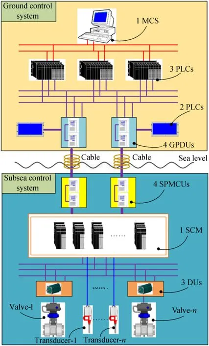
Figure 1 Schematic of subsea all-electric XT control system
Ground control system:The MCS is the core and brain of the control system. It issues all control commands, and the sensor data are recovered to realize real-time monitoring of the working status.The CCU is composed of three PLC.The MCS sends control instructions to the CCU to complete the order.Simultaneously,the CCU reports the collected data to the MCS.The GPDU mainly has two functions.First,it provides electrical support for the mechanical system and the control system and, second, it realizes photoelectric conversion of the control signal.The UPS,which is connected to the system for power supply,is used as a redundant power support measure for when the main power supply system fails.
Subsea control system:The power and communication signals transmitted from the shore are modulated and sent to the SCM by the SPMCU.The SCM is installed on the all-electric XT and directly controls the valve DU. Each DU drives the opening and closing of the valve through servomotors.
The subsea all-electric XT demands extremely high reliability.Thus,the control system design of the whole machine adopts the fault tolerance technique.The units of various electric equipment are connected in series,parallel,or the two-outof-three voting system mode. A triple-module redundancy system is constructed as a whole, and the CCU consists of three PLC processors with the same model.Failure is allowed to happen on one of the PLC processors,while the other two functioning PLC processors are still able to execute control instructions normally. Similarly, the terminal valve drive module includes three identical servomotors; one of them is allowed to undergo failure,while the two remaining servomotors could complete the driving process.
Two control circuits—the master control and the standby control circuits—are found at the left and right side from the MCS to the terminal.Any one of the two control circuits could perform the control of the system, and in normal working conditions, the master control circuit functions, while the standby control circuit provides backup.Once the master control circuit fails,the standby control circuit will immediately step in and perform the control functions. Both circuits are configured in double-module redundancy and are in parallel;thus,failure in one circuit will not influence the operation of the other.Electrical modules in each control circuit have series structures.However,they have more than two identical electrical units in one module subject to specific needs.Therefore,redundant configuration of electrical units is realized in each module,and the number in the figure denotes the number of electric units in the corresponding module.
2.2 Markov Model of Control System
The CCU and the terminal DU are triple-module redundancy control systems with a two-out-of-three voting system.Three PLC processors and three servomotors execute 3-2-1-0 voting,while both the GPDU and the SPMCU adopt the doublemodule redundant parallel system and execute 2-1-0 voting.The results of 3-2-1-0 voting and 2-1-0 voting are shown in Table 1,in which A,B,and C represent operation units,and 1 means normal function,while 0 means failure.3-2-1-0 voting allows one component to fail,and the remaining two components can still ensure that the system works normally.When two or more components fail,the system fails.Similarly,2-1-0 voting allows only 1 component to fail.

Table 1 Voting results of 3-2-1-0 and 2-1-0
As the entire control system is composed of many components, the overall Markov model is extremely complicated,which is not conducive to calculation and analysis.Therefore,the entire control system is divided into the ground control system and the subsea control system for analysis.The problem of state space explosion caused by Markov model with the increase in the number of components is effectivelyavoided.Also,ground and subsea maintenance strategies and component forms vary because of the particularity of the subsea all-electric tree control system.A two-part analysis can not only improve the accuracy of the evaluation results but also provide targeted feedback to determine ways to improve system reliability.
The ground control system consists of 1 MCS,2 UPSs,3 PLCs, and 4 GPDUs, while the subsea control system comprises 1 SCM,3 DUs,and 4 SPMCUs.Seventeen states are defined for the ground control system and denoted by circles,with S0-S15 representing normal working states for the system, while SF1 indicates that the ground system fails. The number in the circles denotes the number of GPDUs, PLCs,UPSs,and MCS in a normal working state from left to right when the system is functioning.
For example,“4321”for state S1 means that 4 GPDUs,3 PLCs,2 UPSs,and 1 MCS are working normally.States S1-S15 are degraded from S0,indicating that the control system is still working even though one or more parts have failed,which fully demonstrates the reliability of the fault tolerance technique for the control system.Similarly,9 defined states exist in the subsea control system,and the numbers in the circle are the number of normal working SPMCUs, DUs, and SCM from left to right, while SF2 means that the subsea control system fails. Markov models for the ground control system and the subsea control system are established based on the 3-2-1-0 and 2-1-0 voting systems and the control system.CCF means that two or more redundancies fail simultaneously due to a common cause(Sakurahara et al.2019;Chebila 2018).In this paper,the fault tolerance technique is used to design the subsea all-electric XT control system.However,CCF nullifies the advantages of the fault tolerance technique.The influence of CCF on the reliability of the fault-tolerant control system for the subsea all-electric XT is discussed. As shown in Figures 2 and 3, the Markov models for the ground control system and the subsea control system are established without considering CCF for the all-electric tree control system.
In the Markov model without considering CCF,the case of a single-component failure is considered under the situation of redundant combination for the same model.For instance,the transition from state “S0, 4321” to state “S3, 3321” exists,signifying that only one GPDU fails,while the transition from state “S0, 4321” to state “S7, 2321” is not considered. This type of transition is called one-level degradation transition.Therefore, one-level degradation transition only considers the situation where only one component of the redundant components of the same type fails.
Based on Figures 2 and 3,a Markov model that considers CCF is established.Under the situation of a redundant combination for the same model in the control system considering CCF,two or more components may fail simultaneously.For example, the transition from state “S0, 4321” to state “S7,3321” means that two GPDUs fail; this condition is called multilevel degradation transition with CCF taken into consideration. Similarly, the transition from state “S0, S1, S1, S2,S2,S3,S4,S4,S5,S6,S8”to state“S11,S9,S13,S10,S14,S11, S12,S15, S13,S14, S15” occurs in the ground control system.The transition from state“S0,S0,S1,S1,S2,S4”to state “S3, S6, S5, S7, S6, S7” occurs in the subsea control system. The established Markov models for the all-electric XT control system considering CCF are shown in Figures 4 and 5.The red arrow in the figure indicates the arc of the state transition considering CCF.
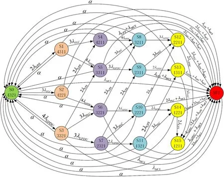
Figure 2 Markov model for the ground control system without considering CCF

Figure 3 Markov model for subsea control system without considering CCF
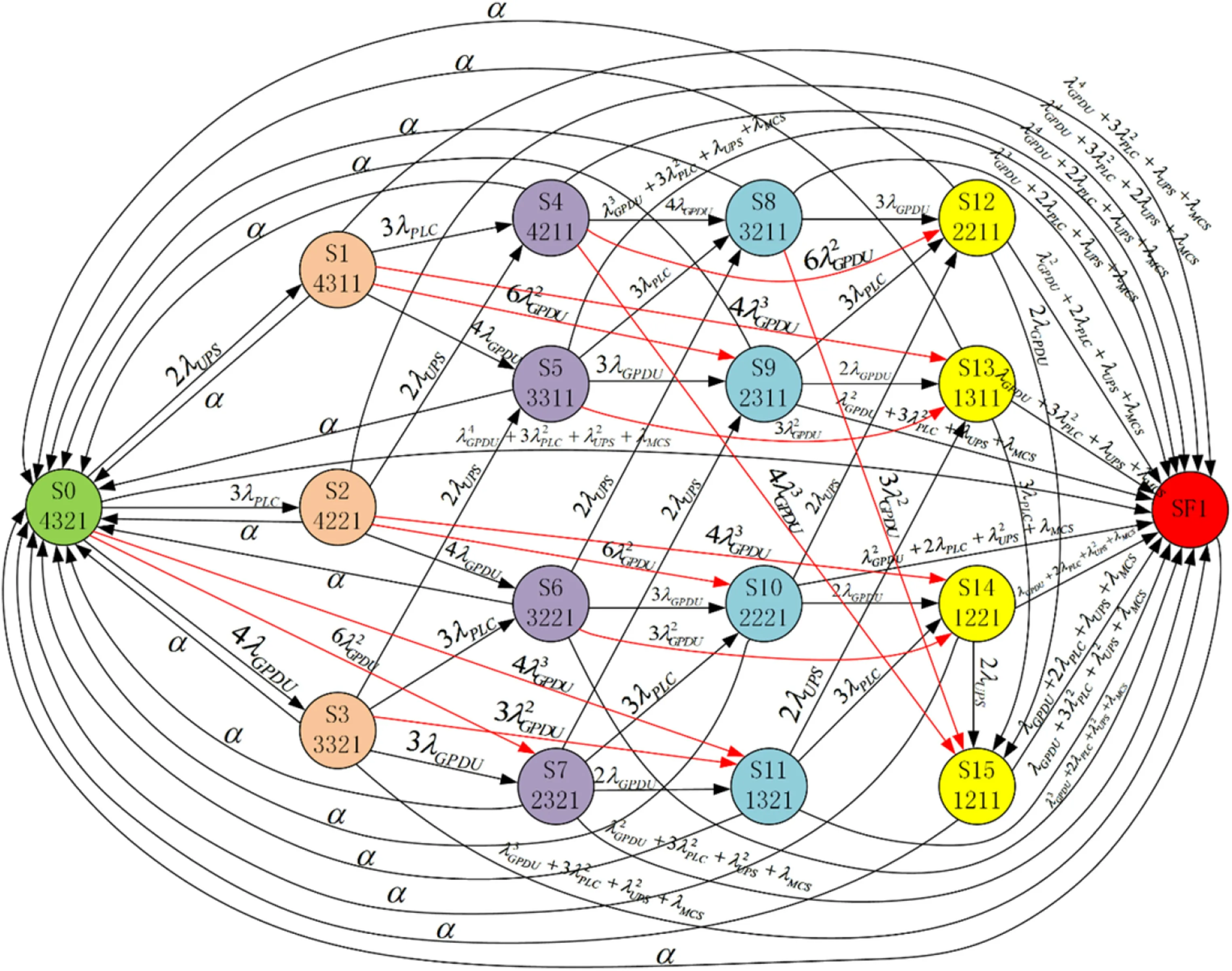
Figure 4 Markov model for the ground control system considering CCF
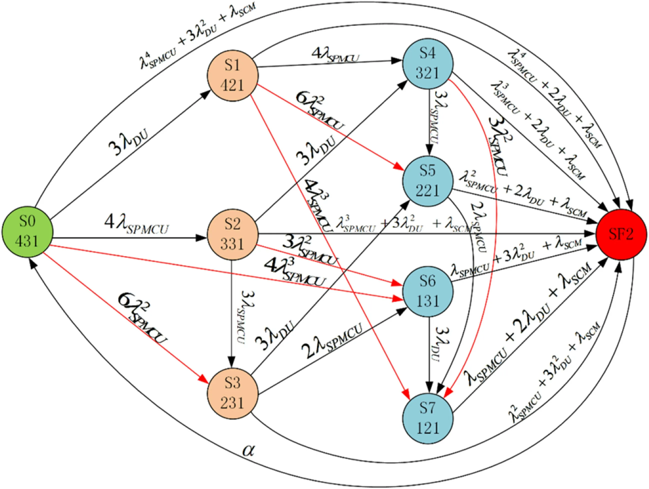
Figure 5 Markov model for subsea control system considering CCF
Based on the memoryless characteristic of the Markov model, the reliability and time to repair components should follow the exponential distribution. The directed arc means that the component transitions from one state to another and the symbol on top of the arc show the state transition probability.For instance,in the Markov model for the ground control system,the transition probability from state“S14,1221”to state “SF1” is λGPDU+2λPLC+λUPS+λMCS, which indicates that 1 GPDU or 1 UPS or 1 MCS or 1 PLC out of 2 PLCs fails.Definitions for the failure rates of components are shown in Table 2.The repair rate of all the components is defined as α. The ground control system is located on land and can be repaired at any time. Thus, each component has an arc pointing toward state S0.In contrast,the subsea control system is salvaged onto land for repair when the overall system fails to function.Thus,the repair rate arc exists only from state SF2 to state S0.
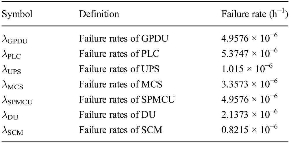
Table 2 Definitions for the failure rates of components
2.3 Dual-Factor Degradation Model of Control System Components
The aging of electrical components occurs objectively over time (Cao et al. 2019). Additionally, the influence of other factors on the components will change the failure rate.Therefore, the traditional reliability evaluation methodassumes that the failure rate of the component remains unchanged and the evaluation result is deviated from the actual result.The performance of electrical components will naturally deteriorate as the working time increases,which is why the reliability degradation trend under natural use needs to be considered.Personnel experience and improper operation also have a certain impact on the reliability of the control system.Even rigorously trained and experienced operators can perform misoperations, which is one of the influencing factors to be considered in the control system reliability evaluation process. Therefore, we propose a dual-factor degradation model for the reliability evaluation of the control system to improve the evaluation accuracy.Dual factors are component degradation factor and human misoperation factor.
2.3.1 Component Degradation Factor
The components of the electrical control system of the allelectric XT comply with the general life cycle degradation law of general electrical components, and the reliability of each component after degradation is calculated according to Eq.(1):

The relationship between the instantaneous failure rate and the reliability of the component is shown in Eq.(2),where f(t)is the failure probability density function and follows the Weibull distribution (Lihou and Spence 1988). The values of the Weibull distribution parameters of the corresponding components of the all-electric tree control system are shown in Table 3(Cai et al.2016a,b).Finally,the degraded failure rate of the component(Γ)after a specific time can be obtained.

Table 3 Parameters of the Weibull distribution for components of control system

2.3.2 Human Misoperation Factor
Misoperation occurs randomly and with a certain probability during the production process of natural persons(Xie and Guo 2018), which should conform to the normal distribution and follow the 3σ principle. Its probability density function is shown as follows:

Assume that the engineering personnel underwent strict training and their work has high operation accuracy.Therefore, they believe that the probability of misoperation should be P{|x-μ|>3σ},which is a small probability event.Thus,the probability of the component degradation due to the superposition of the human misoperation factor is as follows:

where λ is the component failure rate,Γ is the degraded failure rate of the component after a specific time,and λxis the calculated component failure rate after considering the influence of dual factors.
2.4 State Transition Matrix for Control System Without Considering Common Cause Failure
Before the state transition matrix of the control system is calculated,some basic assumptions are made.
1) At the initial state of the control system, all the components function without failed parts.
2) The failure rate and the repair rate follow exponential distribution.
3) The states of all the components are independent of each other.
4) The repair rates are all α.
5) The repaired system can be recovered to the initial state.
6) The reliability of the remaining components is 1.
Three connection methods for the control system exist:series, parallel, and the two-out-of-three voting system.When two components are connected in series,the series state transition matrix PSis as follows:

where λxis the failure rate of series components, while the subscript x denotes the name of the corresponding component.α is the repair rate,as described above.
In parallel cases,four components in parallel are taken as an example, and the parallel state transition matrix PPis as follows,where the numbers 1-4 represent the serial number of the four components,respectively,with the same model:

The state transition matrix PTfor the case connected by the two-out-of-three voting system is as follows,and its symbols are consistent with the series and parallel state transition matrices:

Starting from the initial state,according to the connection mode of each component, a corresponding state transition matrix can be obtained without considering common cause failure.Matrix elements can be transformed into the transition probability on the state transition arc,as shown in Figures 2 and 3.
Each state possesses the Markov characteristic, and the repair rate(Carroll et al.2016)can be calculated by

where α is the component repair rate and MTTR is the mean time to repair for the component.To simplify the calculation of the Markov model for the control system, the MTTR of each component is assumed to be the same and set to 5 h based on experience.
2.5 State Transition Matrix for Control System Considering Common Cause Failure
If CCF is considered,then the transition from one state to another is multilevel degradation, which exists only when components with the same model are non-series-connected. In the specific control system in this paper,CCF refers specifically to the failure of multiple components of the same type. Series components in the proposed control system are different types of components. Therefore, when two components are connected in series, the failure of one component will cause the series circuit to fail. Thus, considering CCF is meaningless because the state transition matrix is the same as the one when CCF is not considered:


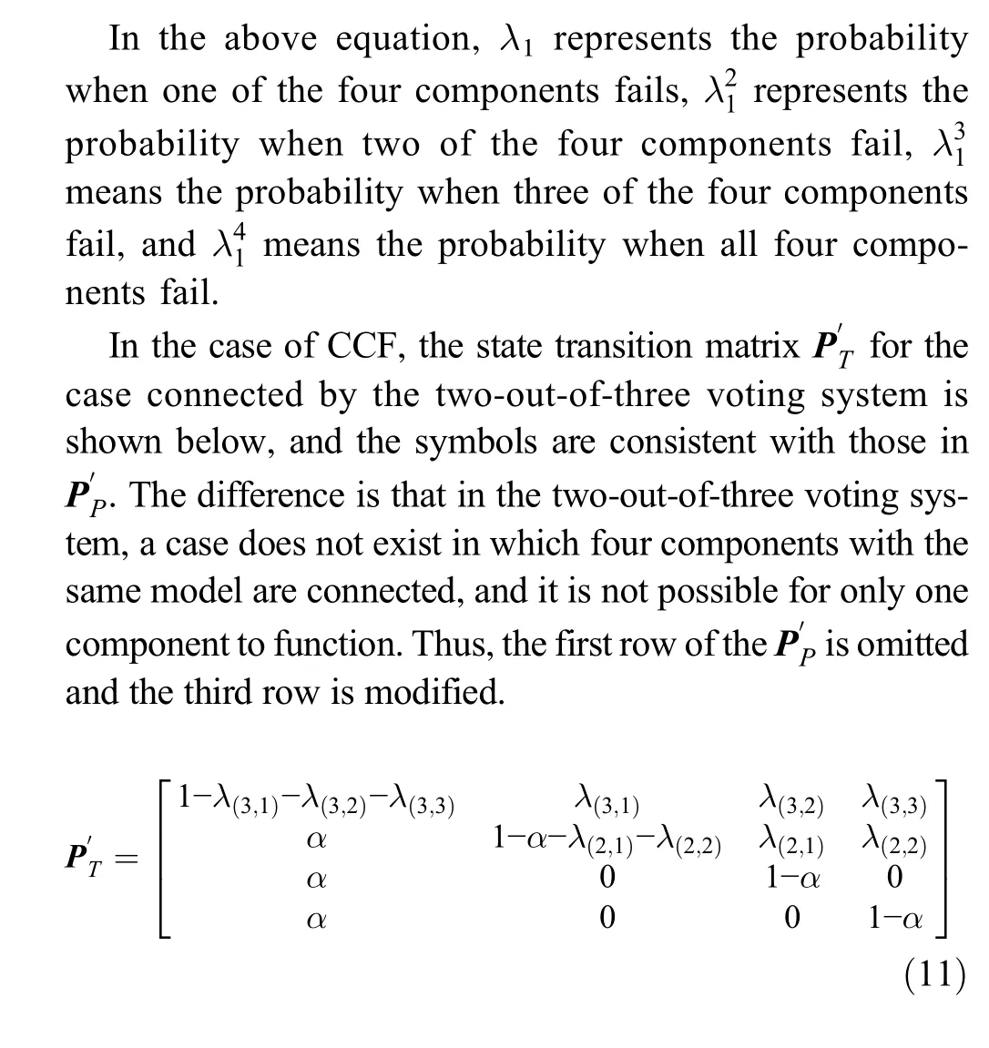
Starting from the initial state,according to the connection mode of each component, a corresponding state transition matrix can be obtained with the common cause failure taken into consideration. Matrix elements can be transformed into the transition probability on the state transition arc,as shown in Figures 4 and 5.
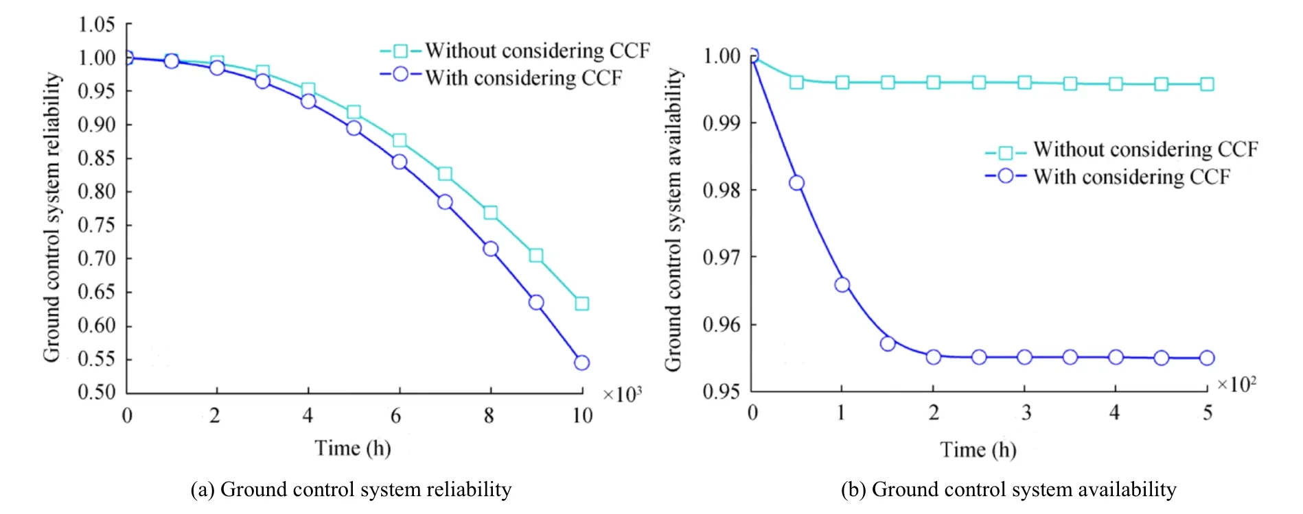
Figure 6 Reliability and availability curves of ground control system
2.6 Validation of Modeling
Validation is an important aspect of a proposed model because it provides a reasonable amount of confidence to the results of the model. Several approaches are applied appropriately to the different aspects of a particular model, including sensitivity analysis, response analysis,response surface modeling, and external validation(Rathnayaka et al. 2012). To perform a full validation of the model, the parameters used would need to be closely monitored for a long period of time. For the subsea XT control system, such long-term monitoring is obviously an impractical exercise. In the current work, a three-axiom-based sensitivity analysis method is used for partial validation of the proposed modeling. The following three axioms should be satisfied (Jones et al.2010):
1) A slight increase/decrease in the failure rate of one component should certainly result in the relative increase/decrease of the evaluation result.
2) Given the variation of the failure rate of components,its influence magnitude on the evaluation result should remain consistent.
3) The total influence magnitudes of the combination of the probability variations from λxattributes on the values should always be greater than that from λy(λx>λy)attributes.
3 Analysis of Reliability and Availability for Control System
3.1 Instantiation of State Transition Matrix
The state probability M(t)of the system at a certain moment can be obtained based on the state transition matrix above,which is shown in the following equation:

P(t) is the state transition matrix at time t. To show the relationship between P(t)and the transition matrices for series,parallel, or two-out-of-three voting system, P(t) is written in the following form.For the ground control system,17 system states exist.

where the first two digits of the four-digit number means the initial state at the moment and the following two digits represent the prescribed state after transition from the initial state.For example,“a0302”means the transition rate from state“S3”to state“S2”in the ground control system Markov model.If a transition arc exists,then the transition rate is the value of the expression on top of the arc;if no transition arc exists,then the transition rate is 0.
For instance, when CCF is considered, P(t)Gis quantized as:
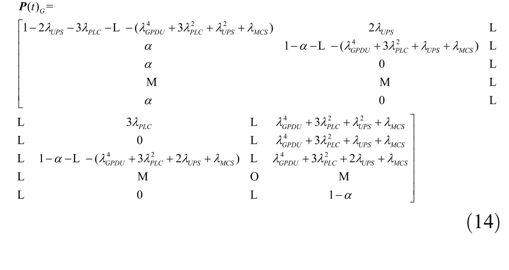
Nine system states for the subsea control system exist,and P(t)is written as:

For instance,when CCF is considered,P(t)Sis quantized as:
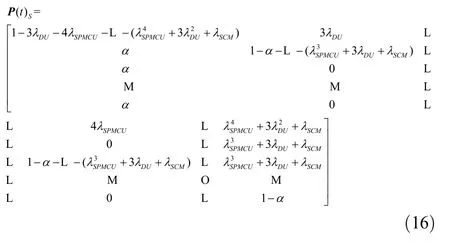
The reliability of a system is a performance indicator that evaluates the normal operation for an uninterrupted period in a certain system.In detail,it is a function of working time and failure rate for a system that starts to work till failure without repair in the process.The availability of a system is an indicator of the evaluation of operation capability in a certain system life circle.It allows for repair and recovery to work if components fail in the process and is,thus,a function of repair rate,failure rate,and working time.
The instantaneous availability of the system A(t) can be calculated by the following equation:
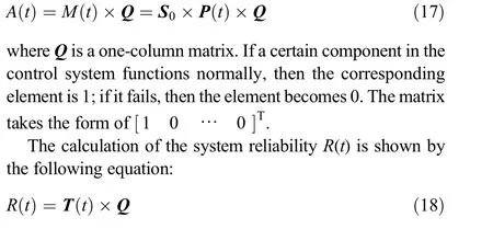
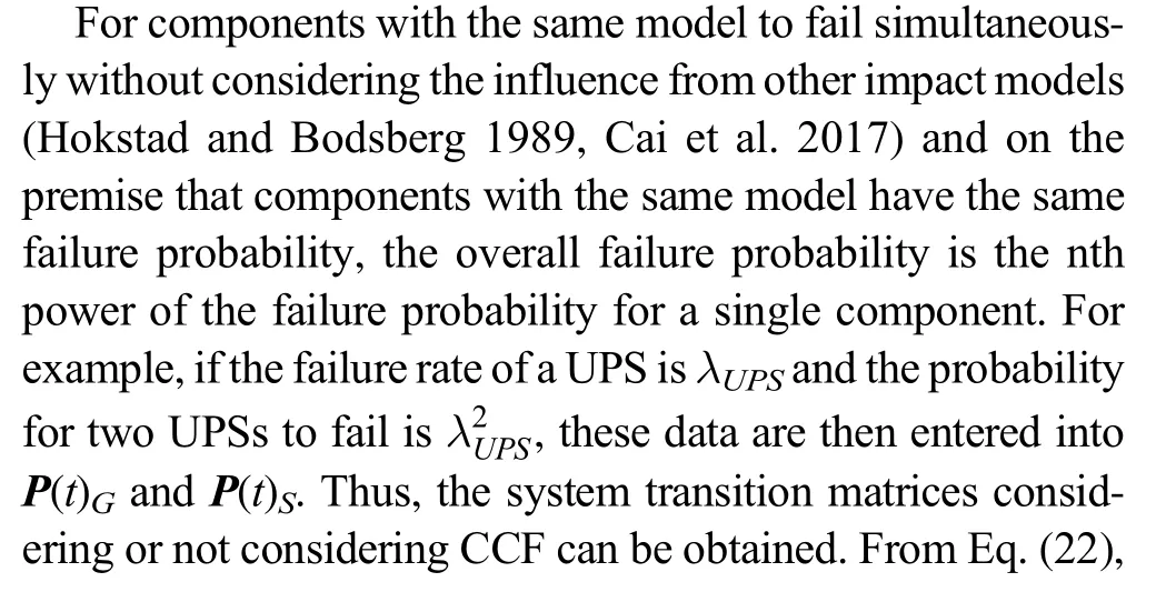
where T(t)is the matrix excluding the repair rate from M(t).the availability of the ground and subsea control system as a function of time t can be derived,and deleting the repair rate in the system transition matrix can obtain the reliability of the ground and subsea control system as a function of time t.
If the availability and reliability probability of the ground control system are recorded as A(t)Gand R(t)G, respectively,then the availability and reliability probability of the subsea control system are recorded as A(t)S, and R(t)S, respectively.The availability and reliability calculation formulas of the entire control system are given by Eqs.(24)and(25).

3.2 Influence of Common Cause Failure on Reliability and Availability for Control System
The system reliability curve in the first 10 000 h and the availability curve in the first 500 h of the ground control system of the subsea all-electric XT are shown in Figure 6.The reliability of the ground control system decreases over time;the decrease in reliability is slow in the first 2000 h and accelerates after 4000 h of continuous working. The system reliability considering CCF decreases more quickly than that of the case without considering CCF.Therefore,CCF could reduce the reliability of a fault-tolerant system and cannot be neglected in the control system of the subsea all-electric XT.
After the ground control system has been working for 10 000 h,the reliability considering CCF or not was reduced to~0.52 and 0.62, respectively. The absolute difference is 0.1,which gradually increases with time, thereby indicating that the working capacity of the system should be paid sufficient attention to avoid failure. A reasonable operation mode requires downtime maintenance when the system has been working for a certain period of time. As can be seen in Figure 6a, when CCF is considered, the system reliability reduces to 0.8 after functioning for ~7000 h in a row,which can be used as the timing node for downtime maintenance in a ground system.
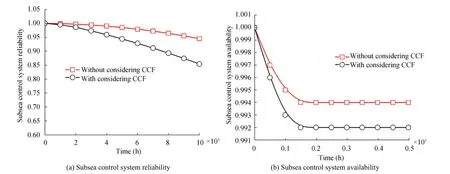
Figure 7 Reliability and availability curves of subsea control system

Figure 8 Reliability and availability curves of entire control system
As shown in Figure 6b, when CCF is not considered, the availability of the ground control system basically remains the same.The system can be repaired at any time,which is why the system availability is rather stable.If CCF is considered,the availability of the system quickly reduces to ~0.957 in the first 150 h and slowly decreases afterward, thereby showing that CCF could reduce the availability of the ground system,especially in the first 150 h.
The system reliability curve in the first 10 000 h and the availability curve in the first 500 h for the subsea control system of the subsea all-electric XT are shown in Figure 7.Figure 7a shows that the reliability trend for the subsea control system of the subsea all-electric XT is basically consistent with that of the ground control system. However,within the same time frame,with or without considering CCF, the reliability of the subsea control system is always higher than that of the ground control system. Even when the subsea control system has been working for 10 000 h, the reliability is still higher than 0.85. The reason for this condition is that the subsea control system has only nine system states, whereas the ground control system has 17 system states. Thus, the smaller number of components in the subsea control system than that of the ground control system is conducive to enhancing system reliability. Similarly, CCF could reduce the reliability of the system.
Figure 7b shows that the availability curve of the subsea control system is different from that of the ground control system.Whether CCF is considered or not,the system availability quickly drops in the first 100 h,and the system availability becomes stable after 150 h.The subsea control system can only be salvaged for repair on land when the whole equipment fail; thus, only one repair arc from state “SF” to “S0”exists, while no other repair arcs pointing to “S0” exist for other states, thereby rapidly reducing the availability of the subsea control system.Similarly,the availability considering CCF is lower than the case without considering CCF, and CCF could reduce the availability of the subsea control system and, thus, is a factor that requires serious consideration for subsea control systems.
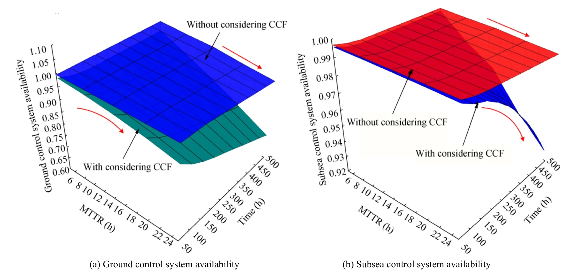
Figure 9 Relation between the MTTR and the availability of the control system
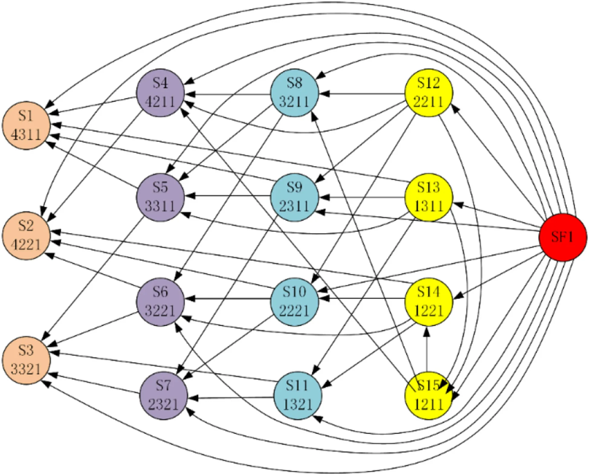
Figure 10 Incomplete repair probability arc of ground control system
The relationship between CCF and the reliability and availability of the entire control system is shown in Figure 8.The figure shows that the CCF has a small impact on the reliability of the entire control system and will cause a slight decrease in reliability. However, the CCF has a greater impact on the availability of the entire control system and will quickly reduce the availability of the fault-tolerant control system.Therefore, CCF is one of the factors that cannot be ignored in an all-electric XT control system.
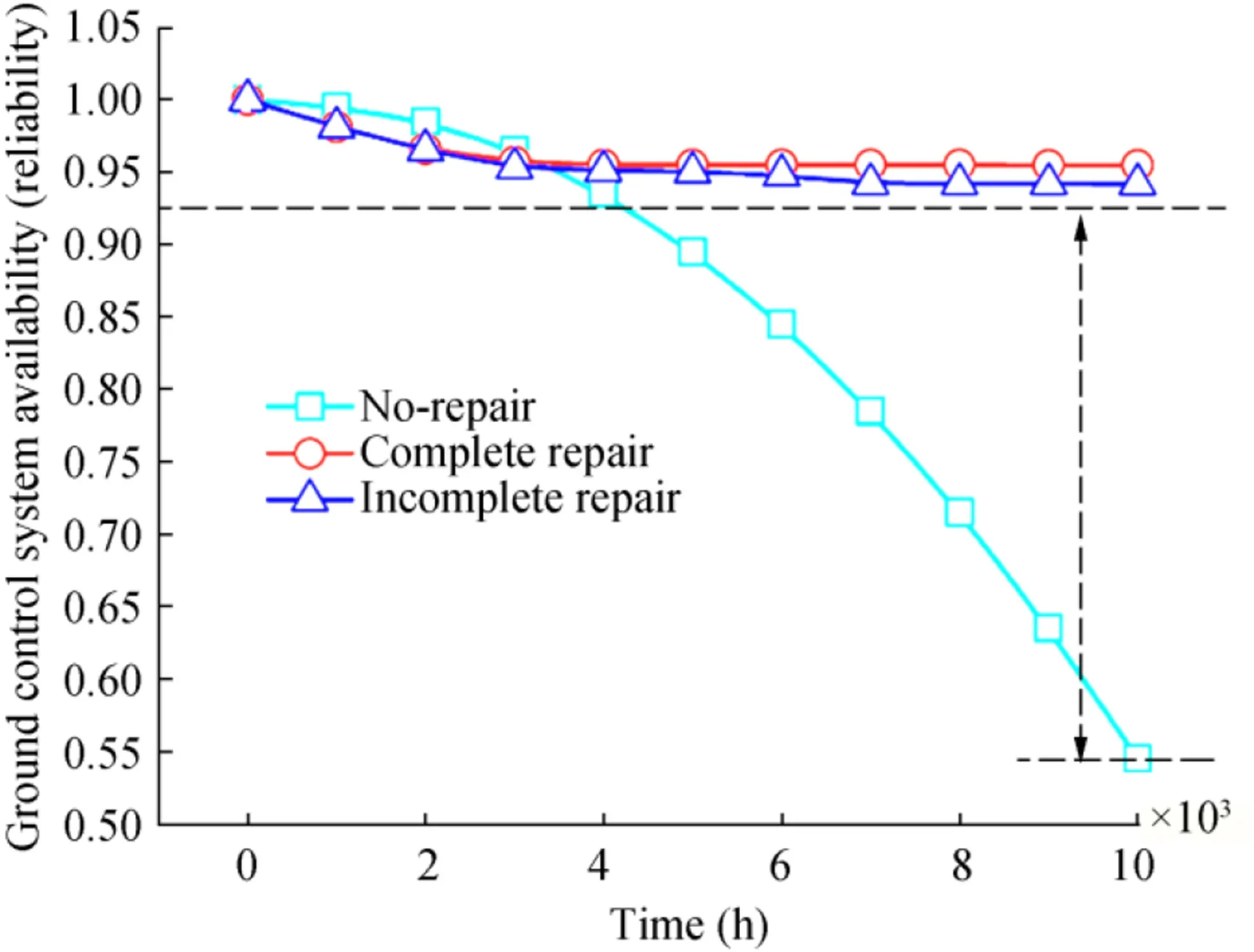
Figure 11 Impact of incomplete repairs on the availability of ground control system
3.3 Influence of MTTR on Availability for Control System
The aforementioned cases suppose that the MTTR of system components is 5 h.In reality,however,the MTTR differs for different types or numbers of failed components. Therefore,the MTTR is a factor that influences the availability of the system. The ground control system and the subsea control system have different maintenance strategies. The ground control system can be repaired at any time,whereas the subsea control system is repaired only when the overall failure occurs.Therefore,the influence of the repair time on the availability of the ground and subsea control system is discussed respectively.For convenience of analysis,the MTTR of each component is still assumed to be the same.
The relation between the MTTR and the availability of the ground control system is shown in Figure 9(a). The MTTR has more obvious effects on the availability of the ground control system, especially when CCF is considered. When the MTTR increases, the rate of decrease in the availability of the ground control system quickens, and when the repair time is ~14 h, the availability reduces to 0.8 with slashed system operation capacity. Therefore, maintaining the MTTR for the control system within a reasonable range is one of the approaches to enhancing system availability.
The relation between the MTTR and the availability of the subsea control system is shown in Figure 9b.The MTTR has more obvious effects on the availability of the subsea control system whether CCF is considered or not.When the MTTR increases, the availability of the subsea control system decreases,and when CCF is considered,the rate of decrease in the system availability quickens. When the MTTR is ~24 h,the system availability reduces to 0.925.Once the subsea control system fails,it has to be retrieved for repair,thereby causing high maintenance costs.Therefore,to maintain high availability of the subsea control system, controlling the system repair time is an effective approach. To make sure that the availability of the subsea control system is higher than 0.98,the MTTR should be guaranteed to be shorter than 6 h.
The ground control system and the subsea control system have different maintenance strategies. Once the subsea control system fails,all components need to be checked when they are salvaged for maintenance so that the reliability of all components is restored to 100%; this process is called complete repair. In contrast,the ground control system has multiple multilevel degradation transitions, which can be repaired at any time.Therefore,ground control system can be shut down for maintenance at any time. If complete repair is conducted, then the MTTR will increase, so only the faulty component can be repaired.After the repair,the system can work normally,but it does not mean that all components are restored to the initial state;this situation is called incomplete repair.The Markov model of the ground control system considering incomplete repair is shown in Figure 10.The directed arc in the figure indicates the incomplete repair probability arc.The incomplete repair probability of each component is still assumed to be the same.
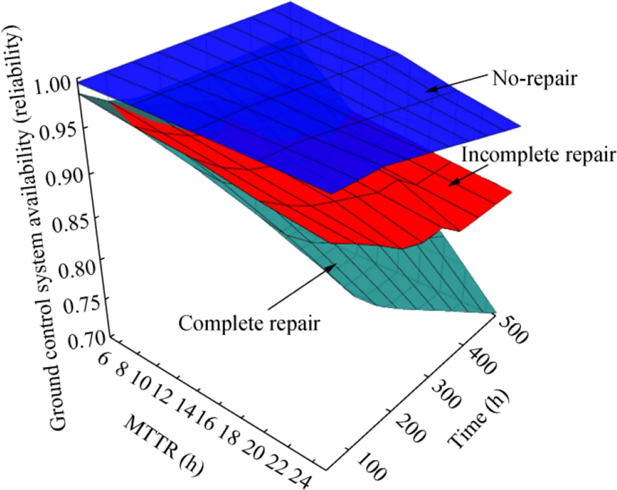
Figure 12 Relation between the MTTR and the availability considering incomplete repair
The relationship between the impact of incomplete repairs on the availability of ground control system is shown in Figure 11. The no-repair curve in the figure represents the trend of system reliability changes.If the components are incompletely repaired,then a certain degree of system availability will occur,resulting in a slight reduction in system availability.The relationship between the MTTR and the availability of the incomplete repair system is shown in Figure 12.The MTTR has a relatively small impact on the availability of the system considering incomplete repair and has a greater impact on the availability of the completely repaired system,thereby accelerating the reduction of system availability.This finding indicates that incomplete repair can greatly reduce the impact of MTTR on the availability of the ground control system.When the MTTR reaches 24 h,the system’s availability can still remain above 0.86. For ground control systems, if all components are inspected one by one for complete repair,then it will inevitably lead to an increase in MTTR,which is generally not conducive to maintaining high availability of the system. Therefore, an incomplete repair strategy should be implemented for the ground control system.Once an electrical module failure occurs, a reasonable strategy is to repair the module without comprehensive maintenance,which is beneficial to reducing the MTTR of the module. Considering the entire life cycle of the system, this method effectively improves the availability of ground control systems.
3.4 Influence of Component Failure Rate on Reliability and Availability for Control System
The influence of the failure rate for a single component on the reliability and availability for the ground and subsea control system when CCF is considered,respectively,is studied.The MTTR is set to 5 h,the operating time when investigating the reliability is 1000 h,and the operating time when investigating the availability is 50 h.The relation curves between the component failure rate and system reliability and availability obtained by multiplying the failure rate of each component in a ground control system are shown in Figure 13.
A comparison between Figure 13a and b shows that the component failure rate has a relatively large impact on the reliability of the system while having little influence on the availability of the system.In detail,the influence of the component failure rate on the reliability of the system can be ranked as MCS>UPS>PLC>GPDU,in which the failure rate of the MCS has the largest impact on the decrease in the reliability of the ground control system.When the failure rate of the MCS is enhanced to 2.7 times the original value, the reliability of the ground control system is reduced to 0.97.Therefore, the failure rate of the MCS should be reduced as much as possible to improve system performance.
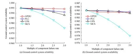
Figure 13 Relation curves between the component failure rate and the reliability and availability of ground control system
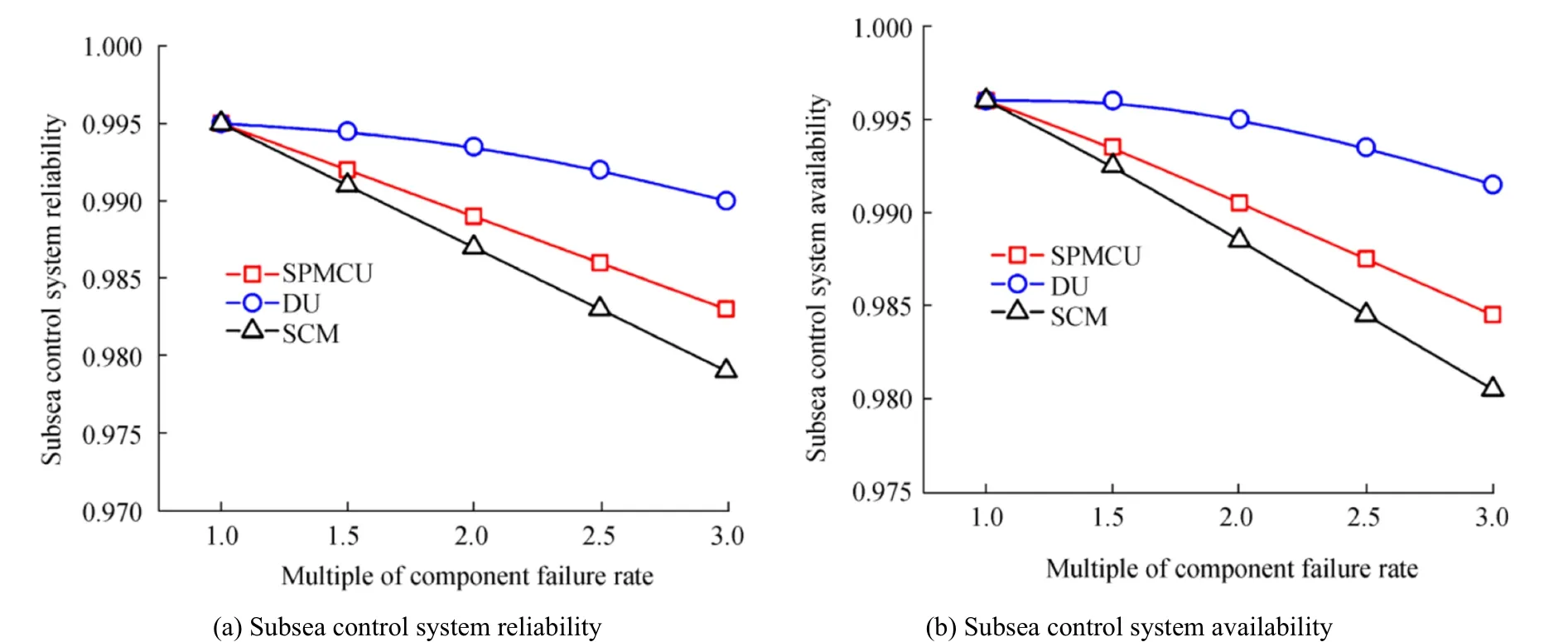
Figure 14 Relation curves between the component failure rate and the reliability and availability of subsea control system
The relation curves between the component failure rate and system reliability and availability for the subsea control system are shown in Figure 14. The influence trends of the component failure rate in the subsea control system on reliability and availability are basically the same. As the component failure rate increases, the system reliability and availability quickly decreases. The influence of the component failure rate on both the reliability and the availability of the subsea control system can be ranked as SCM>SPMCU>DU, in which the failure rate of the SCM has the largest impact with a nearly linear descent trend and the largest slope. When the failure rate of the SCM is enhanced to be around 2.6 times of the original value, the reliability and the availability for the subsea control system are reduced to 0.98 and 0.97, respectively. Thus, the failure rate of the SCM should be reduced to improve the system reliability and availability.
The relationship between the component failure rate and the reliability and availability of the entire control system is shown in Figure 15. The percentage in the figure indicates the multiple of the component failure rate.With the increase in the component failure rate, MCS gradually dominates the reliability of the entire control system, and the GPDU failure rate has the lowest impact on the reliability of the system. SCM has always dominated the availability of the entire control system, and PLC has the lowest impact on the availability of the entire system. Therefore, the failure rate of MCS should be decreased to improve the reliability of the entire control system, and the failure rate of SCM should be decreased to improve the availability of the entire system.
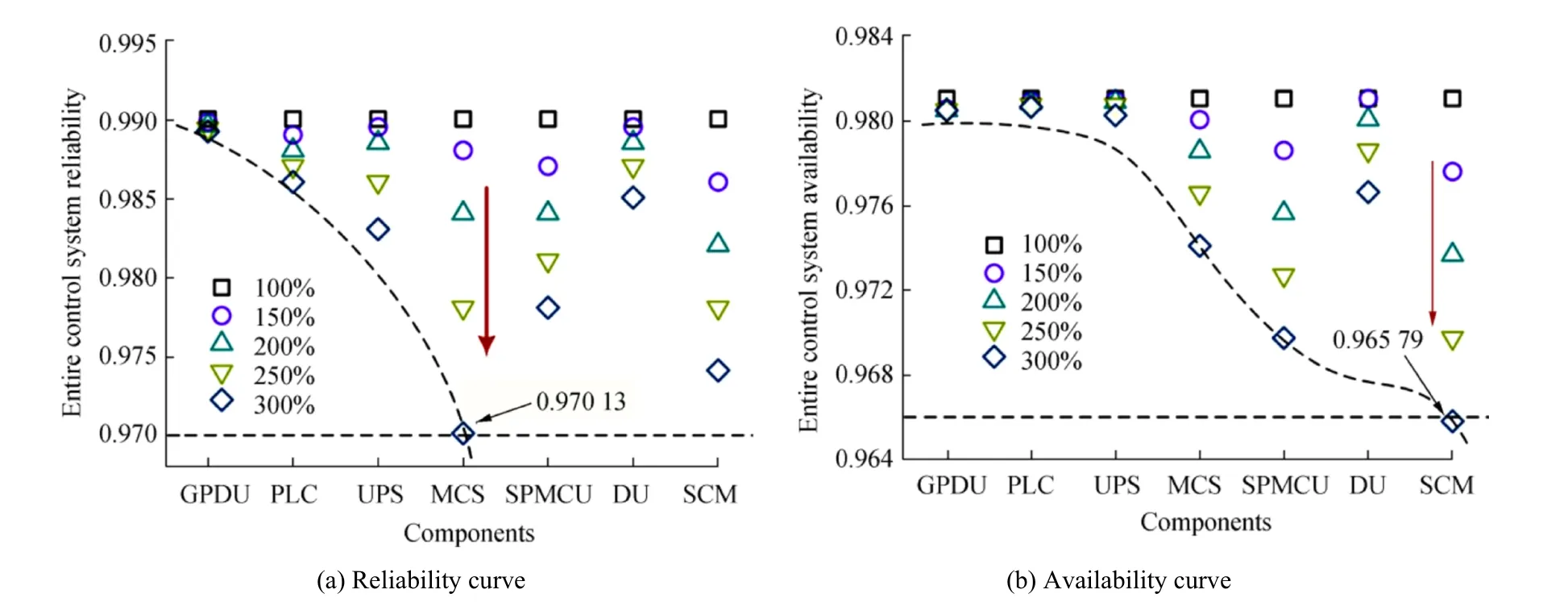
Figure 15 Relation curves between the component failure rate and the reliability and availability of entire control system
4 Conclusions
In this paper,Markov models for the ground control system and the undersea control system for the subsea all-electric XT were established based on Markov theory.A dual-factor degradation model for electrical control system components was proposed,and the influences of the CCF and the failure rate in key components on the reliability and availability of the control system with the series,parallel,or two-out-of-three voting system were studied.The impacts of MTTR and incomplete repair strategy on the availability of the control system were studied,and the following results were obtained:
1) For the same operation time,the reliability and availability of the ground control system decreased more rapidly than those of the subsea control system, especially the system reliability.
2) When CCF was considered, the system reliability and availability both decreased unlike in the case without considering CCF, and the CCF had a greater impact on the system availability.
3) The influence of the MTTR had a greater impact on the system availability,and incomplete repair strategy should be considered to improve the availability of shore-based control systems. For the ground control system, the increase in the MCS failure rate had the largest influence on the reduction in reliability;for the subsea control system,the increase in the SCM failure rate had the largest influence on the reduction in reliability and availability. The failure rate of MCS should be decreased to improve the reliability of the entire control system,and the failure rate of SCM should be decreased to improve the availability of the entire system.
4) If CCF was considered, the ground control system needs downtime maintenance after working continuously for approximately 7000 h to enhance system reliability. As for the subsea control system, the MTTR should be shorter than 6 h to ensure that the availability is above 0.98.
FundingThis study is supported by the National Natural Science Foundation of China under Grant No.61703224.
杂志排行
Journal of Marine Science and Application的其它文章
- Evaluation of the Double Snap-Through Mechanism on the Wave Energy Converter’s Performance
- Numerical Investigation of Sloshing Under Roll Excitation at Shallow Liquid Depths and the Effect of Baffles
- Analysis of Wave Energy Resources Around the Saint Martin Island in Bangladesh
- Fire Risk Quantitative Assessment of Offshore Supported Platform
- Topside Axial Bearing Wear Under the Eccentric Load of a Single-Anchor Leg Mooring System in Bohai Bay
- Fast Tool for Structural Monitoring of a Pier After Impact of a Very Large Vessel Using Ambient Vibration Analysis
