Topside Axial Bearing Wear Under the Eccentric Load of a Single-Anchor Leg Mooring System in Bohai Bay
2021-09-10ShuoYang
Shuo Yang
Abstract Because the applications of single-anchor leg mooring yoke systems (SYSs) are rarely studied in the offshore industry, the design of such systems features some uncertainties. This paper investigated the effect of eccentricity on the wear of the topside axial bearing of a SYS. The eccentricity of the topside was verified by on-site inspection, and the axial bearing wear was found to be far more serious than the original design. The contact status between the axial bearing and flange surface was studied on the basis of the actual topside load by using nonlinear finite element analysis. Wear tests of the topside bearing under uniform and eccentric loads were also performed to study the effect of eccentric loads on the wear rate. The key parameters obtained from numerical simulations and experimentation were used to calculate the wear depth via a simplified linear wear model based on the product of the pressure and sliding distance. Results showed that eccentric loads are the main factor responsible for the excessive wear of topside axial bearings.
Keywords Single-anchor leg mooring · Yoke system · Nonlinear finite element analysis · Wear test · Topside axial bearing
1 Introduction
Single-point mooring systems (SPMs) are applied worldwide to floating production, storage, and offloading (FPSO)units for oil and gas resource development. Single-anchor leg mooring yoke systems (SYSs) are newly developed structures that enable the permanent mooring of FPSO units in shallow water. Several researchers (e.g., Xia 2014;Wenhua et al. 2018) have studied soft yoke mooring systems in Bohai Bay, and these systems have been proven to be among the best types of SPMs for connecting FPSOs and fixed platforms (ABS 1996). However, concerns related to the safety of SYSs have been raised on account of the increasing number of failures reported for other SPMs (Ma et al. 2013a); such incidents could result in massive economic losses for oil field companies. The Statistics of SPM incidents in the past decade was shown as follows: 5 of 10 mooring lines of Banff FPSO parted in 2012 (Teekay Petrojarl 2012), and 2 of 9 mooring lines of Volve FPSO parted in 2011, but there is no damage on the riser (Moxnes 2011).In 2008 and 2010, 3 mooring lines of Jubarte FPSO parted in 2011 (Largura et al. 2011). Four of 8 mooring lines of Gryohon FPSO parted in 2011, and the vessel drifted some distance with the riser broken (Maersk 2011); the same accident also happened on Nan Hai Fa Xian FPSO (Wang 2012).Seven of 10 mooring lines of Liuhua FPSO parted in 2009,and the vessel drifted some distance with the riser broken(Wang et al. 2009). Three (+2 later) of 9 mooring lines of Girassol buoy parted in 2005, but there is no damage to offloading lines (Melis et al. 2005; Vargas and Jean 2005).
The safety behavior of FPSOs has received increased attention in efforts to avert potential accidents. Ma et al.(2013b)studied the yaw motion of the “Fenjin” FPSO with the tide current because such motion may affect the safe operation of the ship. Sun et al. (2012) adopted fault tree analysis to study the safety of FPSOs during crude transfer and fire events. The structural design method and standards of FPSOs have also been evaluated by many researchers(e.g., Moan et al. 2002; Lotsberg and Kristian 2001). In China, fixed tower-type SPMs are widely used in Bohai Bay;compared with other types of systems, the SYS is rarely used. Tang et al. (2018) identified the damages of soft yoke SPM tower systems using long-term monitoring data, and Lyu et al. (2020) proposed a hinge joint damage identification method for soft yoke mooring systems based on structural monitoring data. The incident involving the Hai Yang Shi You in 2009, during which the mooring tower collapsed under strong winds and the vessel was set completely free and drifted some distance away, aroused great interest in the safety of SYSs in the offshore industry (Wang 2012). SPM failures may not only disrupt production continuity but also cause major injuries or loss of life. The lack of established standards for the design and model testing of offshore SPMs could directly contribute to the failure of offshore engineering. Given various failure mechanisms, engineers must quickly manage the emergence of unfamiliar problems not originally foreseen in the design of the system. Therefore,failure analysis of SYSs would be extremely helpful in optimizing the design of mooring systems and improving the reliability of SPMs.
In the present paper, on-site investigations revealed the occurrence of excessive wear in topside axial bearings.Nonlinear finite element analysis of bearings under actual topside loads was conducted to assess the contact status between the bearings and the flange surface. The results of numerical simulations were then compared with visual observations of the topside. Wear tests of the topside axial bearing under uniform and eccentric loads were performed to study the effect of eccentricity on the bearing wear.Finally, key parameters obtained from the numerical simulations and experimentation were used to calculate the wear depth via a simple linear model.
2 Preliminary Examination of SYS Failure
2.1 Description of the SYS Failure
SYSs are used for the permanent mooring of FPSOs in Bohai Bay because the water in this area is shallow. As shown in Figure 1, the SPM includes an “underwater soft yoke” to moor a vessel directly to a fixed tower. The topside includes the jumpers and cables connected to the FPSO, and the top tower of the SYS can rotate along with the yaw motion of the unit. A thrust bearing is used as the axial bearing of the SPM (Figure 1). This type of axial bearing can transfer loads between the rotating and geostationary parts of the topside following the yaw motion of the FPSO.

Figure 1 SYS in Bohai Bay
The SYS was constructed in 2004 and dismantled in 2015 because of a fault in the rotation system caused by excessive wear on the underwater axial bearing. The original topside was then reconstructed onshore to install a new SYS nearby the location of the old SYS. Investigation of the old bearing pieces (Figure 2a and b) of the original topside revealed that the radial and axial bearings had been damaged; specifically, cracks and fractures were found on the bearing pieces. The residual thickness of the old axial bearing pieces was measured on-site (Figure 3), and the minimum thickness was found to be 17.6 mm. Given an original thickness of 30 mm, the average decrease in thickness due to wear was calculated to be 4.0 mm over a service time of only 7 years. Thus, engineers deduced that excessive wear of the bearings was a major contributor to the impact failure of the bearing pieces of the topside.In the present study, detailed failure analyses, including numerical simulations and actual experiments, are performed on the new SYS topside.

Figure 2 Failure of the old bearings on the topside

Figure 3 Residual thickness of the old topside axial bearing
2.2 Failure Analysis
Failure analysis of excessive wear on topside axial bearings has revealed that knowledge of the actual wear of a bearing under eccentric loads is critical for the design of SPMs in the offshore industry. Data on the service life of the wearing parts of the topside may help predict potential hazards,such as safety accidents, and determine the profitability of an SPM. Excessive wear of the underwater and topside axial bearings may lead to low-frequency vibrations of the SYS,resulting in impact failure. A logic tree of the failure analysis of the topside bearings is shown in Figure 4. In this study,validation of the factors indicated in Figure 4 that can cause excessive wear on the old topside axial bearing will be performed step by step through experimentation and numerical calculations.
3 Numerical Analysis and Experiment
3.1 Structural Analysis of Topside Bearings
3.1.1 Finite Element Model
The actual contact status of the topside axial bearing during service was simulated by nonlinear contact analysis using the commercial software ANSYS R14.5. A geometric model of the topside is presented in Figure 5. The finite element model includes decks (Shell143 element), a truss structure(Beam188 element), and the necessary equipment (Mass21 element). The bearings of the topside in this model are constructed from the Solid 95 element. The contact element(target 170 and contact 174) is used to simulate the contact between the bearings and the flange (or the torque tower),as presented in Figure 6. The contact element measures 0.3t×0.3t-0.5t×0.5t, and the element size of the topside structure was 2t×2t. The material parameters applied in the present analysis are given in Table 1. The density of steel is included in the FE model as a material property that must be adjusted in accordance with the SYS topside weight control report.

Figure 4 Logic tree of the failure analysis of the topside bearing

Figure 5 Finite element model of the topside
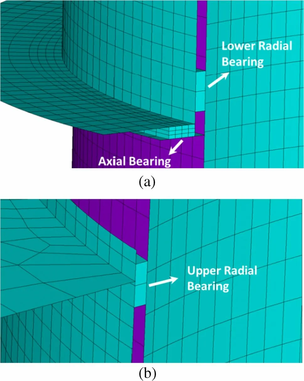
Figure 6 Topside bearing model
3.1.2 Model Loading
In this analysis, the topside was mainly subjected to environmental and operating loads, as listed in Table 2. The maximum moment from the FPSO yaw motion over a 1-year return period was obtained through hydrodynamic analysis, and the static load was obtained through structural calculation.

Table 1 Material properties of the FE model

Table 2 Loads of the top side of the SYS (kN)
The applied load and boundary conditions of the topside are illustrated in Figure 7. The connection between the torque tube and swivel stack is simulated by coupling nodal degrees, and the bottom nodes of the inner tube are fixed.The moment from the FPSO yaw motion is modeled as a force couple, and the wind load is considered a horizontal inertial load applied to the topside structure.FXforces with negative signs indicate mean forces occurring at the surge motion of the FPSO, the direction of which is away from the SYS tower.FZforces with negative signs refer to forces in the same direction as gravity. In this FE model, all nodes in the lower area of the topside are completely restrained.
3.2 Wear Test of the Axial Bearing
Because the actual contact status of the topside axial bearing will be verified by visual observations on-site, a wear test must be performed to evaluate the effect of an eccentric load on the wear of the axial bearing. The bearing is composed of a thermoplastic incorporating polytetrafluoroethylene as a lubricant, which is identical to the bearing material usedin the SYS. The wear test machine and specimens are shown in Figure 8. The upper friction pair is made of Inconel alloy to simulate the practical wear as closely as possible, and the contact width is 9.25 mm. The experimental conditions include dry friction, a machine rotational speed of 60 rounds per minute, and a friction pair contact stress of 0.3 MPa.
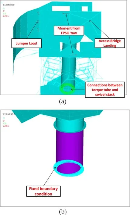
Figure 7 Applied load and boundary condition on the topside
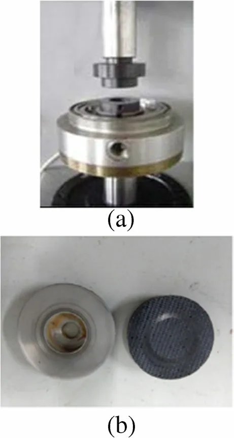
Figure 8 Photographs of the wear test machine and test specimens
In this study, the thickness difference is adjusted to simulate eccentric contact; this difference may be written as follows:

where ΔHuand ΔHlare the respective differences between the maximum (Hu-maxandHl-max) and minimum (Hu-minandHl-min) thicknesses of the upper and lower friction pairs.TakingDas the diameter of the lower friction pair, the tilting angleθcan be derived as follows:

The friction pair used for uniform wear is polished toθ <0.04°(ΔH <0.02 mm) to achieve what may be considered completely horizontal contact. Visual observation of the topside reveals that theθof the friction pair is polished to ΔH <0.1 mm,θ=0.18°to simulate the actual contact status.
4 Results and Discussion
4.1 Finite Element Analysis
The results of finite element analysis (Figure 9) reveal that the distribution of contact stress on the topside axial bearing is non-uniform under the operating load condition and that the maximum contact stress mainly occurs at the FPSO side because the jumper load direction is always along with the surge motion direction of FPSO. Figure 9 also shows that the axial bearing on the opposite side of the FPSO is hardly subjected to the bearing load. Numerical simulations reveal that the load from the topside results in local eccentric contact between the flange and axial bearings.

Figure 9 Contact stresses of the axial bearing
In the original design, the axial bearing only bears the self-weight of the topside structure, and the contact stress under the highest bearing load is 2.6 MPa (APL Norway AS Staff 2003a), much less than the value of 15.30 MPa obtained in the numerical simulations. This difference may be attributed to the fact that the original design does not consider the complete topside load, including the jumper motion load and jumper self-weight on the chute. As shown in Figure 10, the upper and lower radial bearings are also in incomplete contact with the torque tower under a topside load. Thus, less than half of the area of axial bearings bears the vertical load.
The results of the numerical simulation of the wear shape of the topside axial bearing are shown in Figure 11. When the topside load is fully considered, only half of the axial bearing is under the bearing load, and the radial bearing is in local contact with the torque tower.
A comparison of the maximum clearances of the topside bearings determined from on-site measurements and numerical simulations is presented in Table 3; only slight differences in values are observed. Visualizations of the bearings are shown in Figures 12 and 13, which clearly reveal a maximum gap of approximately 6.0 mm between the upper radial bearing and the torque tower at the opposite side of the FPSO. Approximately half of the axial bearing is not in contact with the flange surface, similar to the results of the numerical simulation.

Table 3 Comparison of the clearances of topside bearings determined through numerical simulation and on-site measurements
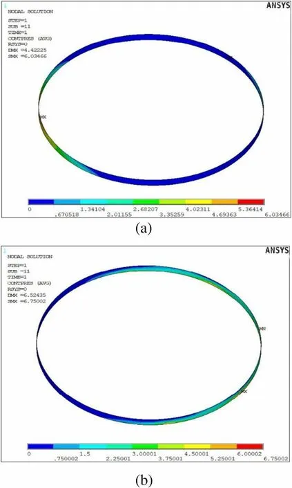
Figure 10 Contact stress results of the radial bearings
The visualizations above clearly indicate that the topside axial bearing is under an eccentric load and that the bearing at the FPSO side is always subject to local wear; in this case,the area of the wear shape is approximately half that of the axial bearing. The nonlinear finite element analysis results obtained in this paper are reasonable when the complete topside operating load, including the jumper load, is taken into account. The displacement caused by the eccentric load may lead to a low-frequency impact load on the bearings under the surge motion of the FPSO.
4.2 Wear Test Results
Figure 14 shows that the value of the wear factor is maintained at 0.11 over 6 h under uniform conditions; this wear factor is close to the design value (0.085) (APL Norway AS Staff 2003a). The unit of wear factor in this figure is 10-14m2/N.

Figure 11 Wear shape of the axial bearing
The eccentric wear test was performed on the basis of the real contact status to simulate local wear on half of the area of the wear shape (Figure 11). The experimental results(Figure 14) of eccentric wear indicate that the wear factor experiences a rapid increase within the first 0.5 h and then stabilizes at 0.52, which is much higher than the wear factor obtained under a uniform load. Thus, eccentricity has a significant effect on wear, and the actual wear rate should be determined for future reassessments of the wear depth. An eccentric wear test with lubricating oil was also performed,and the results are presented in Figure 15. The wear factor under an eccentric load tends to be relatively low and stable with lubrication, and it can be seen from Figure 15 that the temperature data on the wear surface have a positive correlation with wear factor. These test results can help guide future topside bearing maintenance activities.
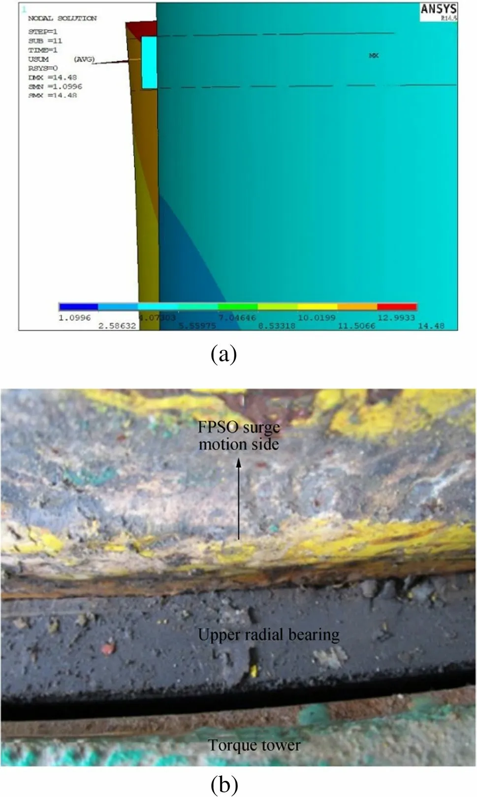
Figure 12 Displacement between the upper radial bearing and torque tower
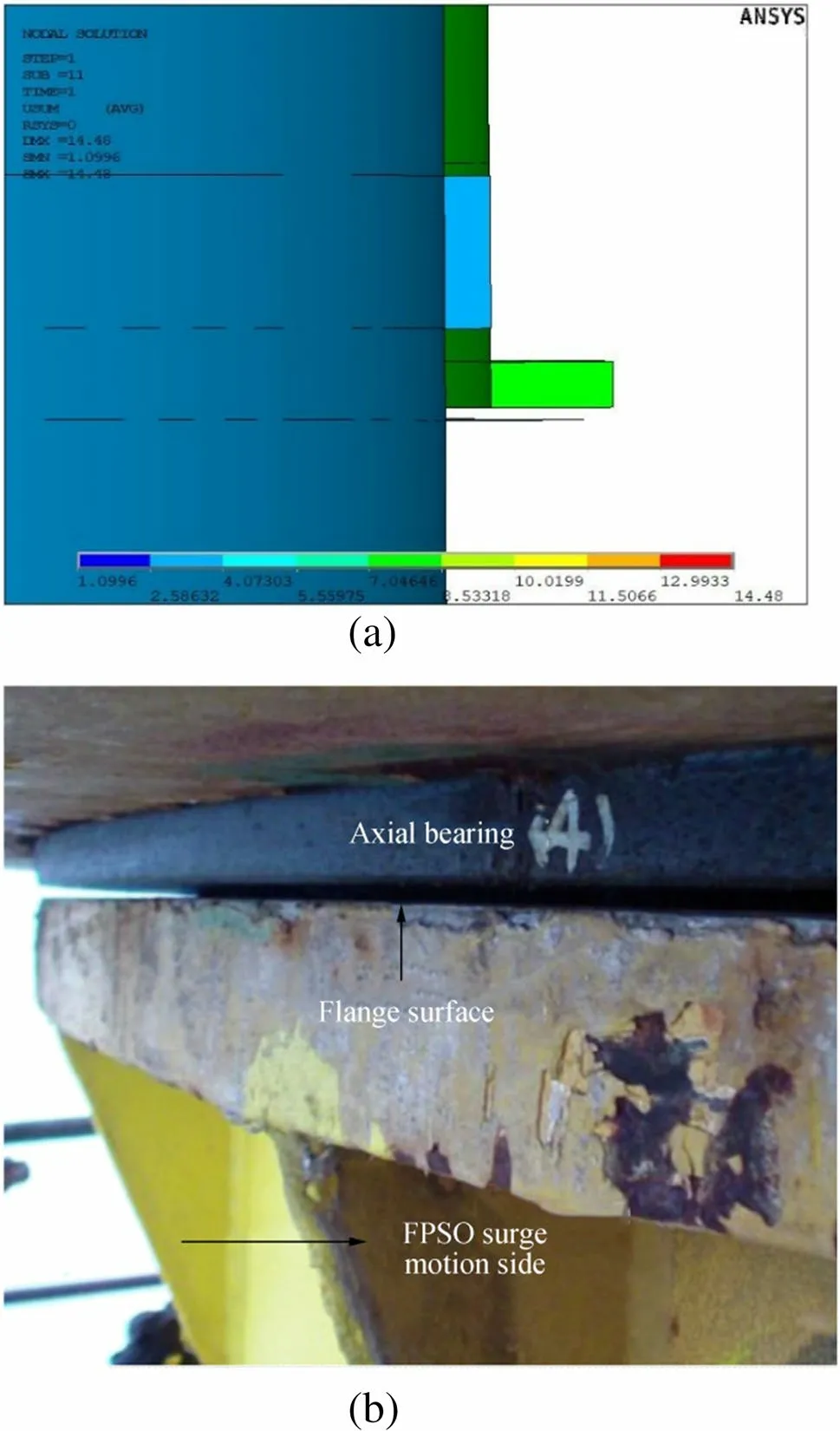
Figure 13 Displacement between the axial bearing and flange surface
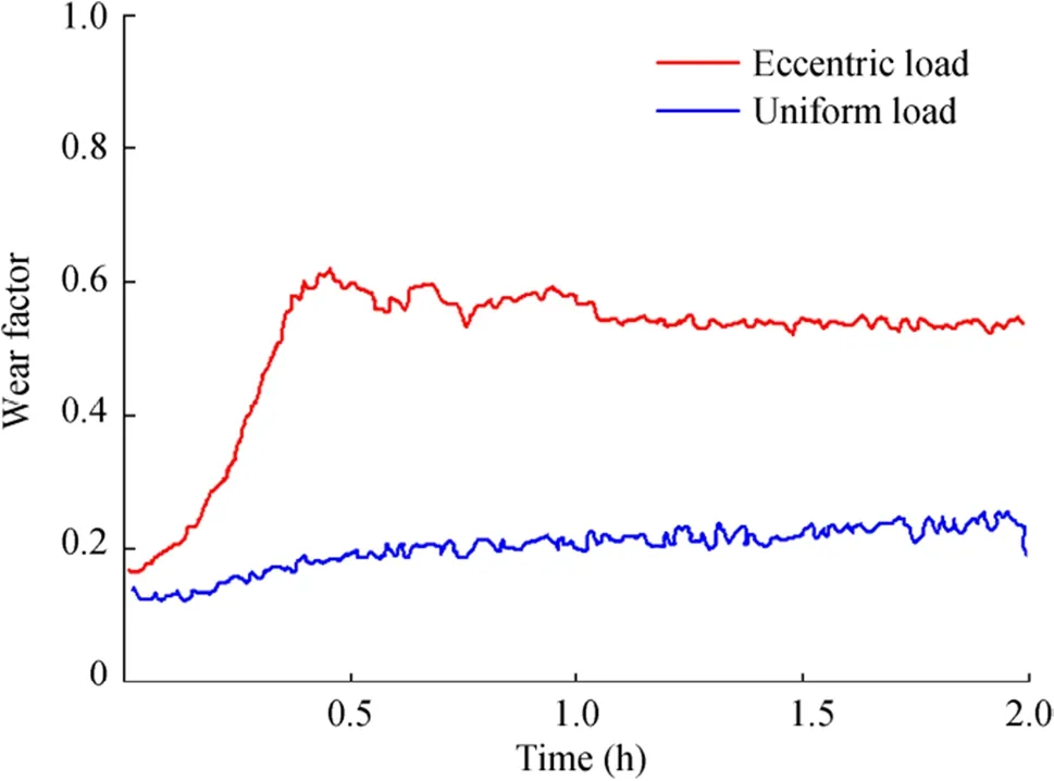
Figure 14 Changes in wear rate under eccentric and uniform loads

Figure 15 Changes in wear rate under an eccentric load with lubricating oil
4.3 Calculation of wear depth
Assessment of the wear depth of the axial bearing was conducted using a simple linear model based on the experimentally determined wear rate, contact stress, and sliding path; the results of such an assessment can be used to predict wear levels throughout the service life of the structure. The calculation model can be written in the following form:

wherewis the wear depth of the bearing,kthe wear rate,which is determined experimentally,pthe contact stress, andsthe sliding length.
Wear is calculated according to Eq. (3); here, the contact stress and wear rate are obtained from the numerical simulations and wear test. The average contact stress in the local area under an eccentric load is 10.2 MPa, and the wear rate derived from the experiment is 5.2× 10⁻¹⁵m2/N. The sliding length refers to the distance over which the bearing surface travels relative to its mating surface and can be obtained from the hydrodynamic analysis (APL Norway AS Staff 2003b) of the complete mooring system. The model presented below does not represent the exact movement of the turret system but is a simplified mathematical model that enables estimation of the sliding path on the basis of statistical data. This model is based on Rayleigh distributed angle maxima (APL Norway AS Staff 2003b) and can be written as follows:

wheresis the annual sliding path,pithe probability of No.isea state,NLF,iandNWF,iare the annual numbers of cycles due to low-frequency motion caused by FPSO drift and wave-frequency motion caused by wave excitation forces,respectively, andαLF,iandαWF,iare the average yaw angle ranges due to low-frequency and wave-frequency motions,respectively. Factor 2 refers to the number of angle ranges in one cycle. The average yaw angle range (APL Norway AS Staff 2003a) due to either low-frequency or wave-frequency motion is given as:

whereσis the standard deviation of the yaw angle amplitude and Γ is the gamma function.
Besides the low-frequency and wave-frequency motions of the FPSO described above, tide change could also contribute to the yaw rotation of the system. If the tide direction changes by 180° four times a day, two complete rotations are obtained each day. Therefore, the sliding path of the topside axial bearing over 25 years is 527 km.
Table 4 shows that the calculation of the original design substantially underestimates the wear depth of the topside axial bearing. Compared with the maximum wear thickness of the topside axial bearing pieces (i.e.,7.40 mm), the wear depth over 7 years calculated in this study (i.e., 7.80 mm) is closer to the actual conditions.The error observed may be attributed to inconsistencies between the results of the experiment and numerical simulations and between the calculated and actual sliding paths. Moreover, the simple model of wear depth ignores nonlinear factors.

Table 4 Calculation of wear depth
Taking the results together, the eccentricity of the topside may be cited as the major factor responsible for the excessive wear of the axial bearings, which is mainly caused by the jumper load on the chute and the surge motion of the FPSO.As gaps between the upper radial bearing and torque tower may lead to low-frequency impact loads, excessive wear on the axial bearings can magnify the load response of the topside radial bearings.
5 Conclusions
A complete analysis, including on-site investigation, numerical simulation, and experimentation, was performed in this study to determine the main cause of excessive wear in topside axial bearings during service. The following conclusions can be drawn.
1) Nonlinear contact analysis indicates that the bearing is always subject to local wear at the FPSO side during long-term service. The results of numerical simulations are consistent with on-site measurements, which means the jumper load on the chute and the surge motion of the FPSO have significant influences on the contact status between the flange surface and axial bearing.
2) The wear test results show that eccentricity increases the wear factor by several times compared with that induced by uniform wear. The test also indicates that lubricating oil is quite useful for reducing wear.
3) A simple model to predict wear depth is developed, and quantitative results indicate that the eccentricity of the topside is the leading cause of bearing wear.
The analysis results also indicate that lubrication and periodic non-destructive inspection are necessary for the maintenance of SYSs. The numerical and experimental findings of this study provide useful information for the optimal design and marine operation of SYSs.
FundingThis study was supported by the Project of China Offshore Oil Engineering Company (Tianjin) CCL2014CFD.
杂志排行
Journal of Marine Science and Application的其它文章
- Evaluation of the Double Snap-Through Mechanism on the Wave Energy Converter’s Performance
- Numerical Investigation of Sloshing Under Roll Excitation at Shallow Liquid Depths and the Effect of Baffles
- Analysis of Wave Energy Resources Around the Saint Martin Island in Bangladesh
- Fire Risk Quantitative Assessment of Offshore Supported Platform
- Reliability Analysis Method of a Control System for Subsea All-Electric Christmas Tree
- Fast Tool for Structural Monitoring of a Pier After Impact of a Very Large Vessel Using Ambient Vibration Analysis
