Analysis of the microstructure and elemental occurrence state of residual ash-PM following DPF regeneration by injecting oxygen into non-thermal plasma
2021-09-10YunxiSHI施蕴曦YiruiLU卢奕睿YixiCAI蔡忆昔YongHE何勇YinZHOU周银YingxinCUI崔应欣andHaomingSUN孙浩铭
Yunxi SHI(施蕴曦),Yirui LU(卢奕睿),Yixi CAI(蔡忆昔),Yong HE(何勇),Yin ZHOU (周银),Yingxin CUI (崔应欣) and Haoming SUN (孙浩铭)
1 School of Automotive and Traffic Engineering,Jiangsu University,Zhenjiang 212013,People’s Republic of China
2 Vehicle Measurement,Control and Safety Key Laboratory of Sichuan Province,School of Automobile and Transportation,Xihua University,Chengdu 610039,People’s Republic of China
Abstract Particulate matter (PM) capture tests were carried out on clean diesel particulate filters (DPFs)under different loads (25%,50%,75% and 100%).DPFs were regenerated by a non-thermal plasma(NTP)injection device.Raman spectroscopy and x-ray photoelectron spectroscopy were used to investigate changes in the microstructure and element occurrence state of the sediment in DPF channel before and after regeneration.The order of the PM samples decreased before NTP treatment as the load increased; the amorphous carbon content was high,and the oxidation activity was higher.After NTP treatment,the carbon atoms at the edge of the microcrystalline structure in the ash-PM samples were oxidized,and the structure was reorganized; in addition,the amorphous carbon content decreased,and the structure was more diversified.Before NTP,the C element of PM samples was the main component,and the content of the O element was relatively low.The C element occurred in the form of C–C,C–OH,and O–C=O functional groups,and O atoms were mainly combined with C–O.After NTP,the content of Na,P,S,Ca,and other inorganic elements in ash-PM samples was prominent because C atoms were removed by NTP active substances.There were two forms of S element occurrence(SO42−and SO32−);the proportion of SO42−was approximately 40%,and the proportion of SO32−was approximately 60%.Study of the microstructure and element occurrence of the residues in the DPF channels improved our understanding of the mechanism of the low-temperature regeneration of DPF from NTP.
Keywords: diesel particulate filter,regeneration,non-thermal plasma,ash-PM,microstructure,occurrence state
1.Introduction
Because of the increasing severity of atmospheric pollution,particulate matter (PM) emissions from diesel engines have received widespread attention.PM is a type of complex aggregate that is mainly composed of dry soot,soluble organic fraction (SOF),inorganic salts and metallic substances [1,2].Out-engine purification technologies for reducing PM emissions from diesel engines mainly include diesel particulate filter (DPF) and diesel oxidation catalyst [3,4].The wall-flow structure inside DPF can separate the PM in the exhaust gas from the airflow and intercept it in the filter pores.The collection efficiency of DPF can be as high as 95% or more,making it the most effective PM emission control technology developed to date [5,6].DPF needs to be regenerated in time to prevent problems such as increased exhaust back pressure and engine performance degradation caused by excessive PM deposits [7,8].
Conventional DPF regeneration methods mainly include active regeneration,passive regeneration or active-passive hybrid regeneration [9].In active regeneration,the DPF carrier is prone to damage because of high-temperature gradients or temperature peaks;the drawback of passive regeneration is incomplete PM removal[10].In recent years,the use of nonthermal plasma (NTP) technology to remove diesel engine exhaust particles has become a major focus of research.Babaieet al[11,12] added diesel exhaust into NTP generators at different discharge voltages to conduct PM removal tests.The results showed that the removal efficiency of PM was over 70%,and the mass removal efficiency of PM was as high as 43.9%.Wanget al[13] directly connected diesel exhaust to a NTP generator and studied the effect of NTP on the diesel PM through scanning electron microscopy,showing that the mean spherule diameters and the degree of agglomeration of PM after NTP oxidation were significantly reduced.Maet al[14,15]designed a NTP generator based on corona discharge theory to purify PM in diesel engine exhaust,and found that NTP reduced the quantity and mass concentration of PM in diesel engine exhaust by oxidation and trapping.The purification effect of NTP on particulate PAHs was analyzed by GC-MS.The results showed that the content of PAHs with small molecular weight increased significantly,with the exception of phenanthrene and anthracene,and the content of PAHs with large molecular weight decreased by more than 80% with the exception of benzopyrene.The removal rates of particulate PAHs and toxic equivalent by NTP were 58.4%and 82.8%,respectively.The above studies confirm that the strong oxidation of NTP active substances can effectively degrade the PM of diesel engine.Consequently,this technology has been applied to the field of DPF regeneration.
In this paper,a diesel engine was used to conduct PM capture tests on clean DPFs with different loads (25%,50%,75% and 100%); the DPF was regenerated by an NTP injection device.The residues (ash structure in carbon: PM and ash structure in ash: ash-PM) in the DPF channel before and after NTP-treated were sampled.Raman spectroscopy and x-ray photoelectron spectroscopy (XPS) were used to analyze changes in the microstructure and element occurrence of PM and ash-PM samples,which revealed the stripping mechanism of NTP on PM in DPF channel and provided new insight into the low-temperature regeneration of DPF by NTP.

Figure 1.Experimental system for the PM capture test.

Figure 2.DPF regeneration test system.
2.Test equipment and process
2.1.PM capture test
Figure 1 shows the PM capture test system.Eight clean DPFs were selected for PM capture,with an engine speed of 2500 rpm min−1and loads of 25%,50%,75%and 100%.As the residues are affected by the carbon load,the carbon load of DPF was lower when the load was lower.To ensure that sufficient residues were deposited in the fully regenerated DPF for analysis,the capture times were 8,6,4 and 2 h.
2.2.DPF regeneration test
Figure 2 shows the DPF regeneration test system,which mainly includes the oxygen cylinder,plasma power supply,NTP generator,cooling device,temperature control device,DPF and gas analyzer.The DPF used in the experiment was cordierite ceramic,and its structural parameters are shown in table 1.The gas source was 99.99% oxygen.The plasma power supply used in the test included a CTP-2000K intelligent electronic impactor and TDS3034B digital oscilloscope.The working voltage range was 0–25 kV,and thefrequency range was 7–20 kHz.The gas analyzer was used to monitor the concentration of the regeneration products CO and CO2during the regeneration process to assess the DPF regeneration process.The NTP generator used in the experiment was a dielectric barrier discharge type,which is a coaxial cylindrical structure.The inner electrode was a low voltage electrode,and the outer electrode was a high voltage electrode.The inner electrode was a stainless steel tube(outer diameter of 48 mm),and the barrier medium was a quartz glass tube (inner diameter of 52 mm,thickness of 2 mm).When the inner and outer electrodes are connected with the CTP-2000K intelligent electronic impactor,the gas in the discharge gap is broken down,which generates O3,O and other active substances.To reduce the temperature of the discharge area and improve the efficiency of active substance generation,internal water cooling and external air cooling were employed by the NTP generator.The temperature control device was used to heat DPF to ensure the initial temperature environment of regeneration.
A regeneration test on the DPF that had trapped PM was performed.In the regeneration test,the flow rate of the gas source was 5 l min−1,the discharge voltage was 18 kV,the discharge frequency was 9 kHz and the temperature control device was 80°C.When the concentration of CO and CO2in the gas analyzer decreased to ‘0’,regeneration was stopped,and the residual ash-PM sample in the DPF filter channel was extracted and placed in a dry vessel for subsequent analysis.
2.3.Nomenclature of samples and analysis
Table 2 shows the nomenclature of PM samples before NTP treatment and ash-PM samples after NTP treatment.Raman spectroscopy was used to analyze the microcrystalline structure of samples before and after NTP treatment.The laser Raman spectrometer used was a DXR type laser Raman spectrometer(Thermo Fisher Co.);it was equipped with three excitation wavelengths: 532,633 and 780 nm.The Raman frequency shift ranged from 100 to 3000 cm−1.The signal-tonoise ratio of the third peak of silicon was higher than 10:1,and the spectral resolution was less than 2 cm−1.Before the Raman spectroscopy test,the sample needed to be spread on the glass slide to form a thin layer with an area of approximately 5 mm×5 mm with uniform thickness.The slide was placed on the observation platform; 3–4 observation points were selected for scanning and each scan lasted 10s.
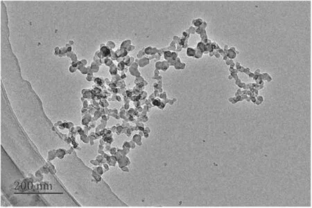
Figure 3.TEM image of diesel PM.
An ESCALAB 250XI x-ray photoelectron spectrometer was used to analyze the element occurrence state of samples before and after NTP treatment.The ESCALAB 250XI XPS spectrometer uses a monochromatic Al K-alpha x-ray source with a photon energy of 1486.6 eV,spot diameter of 500 μm and energy pass of 20 eV.The samples used in the XPS analysis were processed by pressing.The ash samples were ground into fine powder less than 0.2 mm and spread evenly on the aluminum foil.The aluminum foil and samples were flattened by a hydraulic press and cut into appropriate sizes;the upper aluminum foil and lower aluminum foil were then removed.The tablet was placed into the sample table,the position to be analyzed was selected,the sample was excited with x-rays and the photoelectron image of the sample was saved.
3.Test results and analysis
3.1.Reaction mechanism between NTP active substances and PM
Figure 3 shows the TEM image of diesel PM.PM is a complex aggregate that is formed by the combustion or cracking of hydrocarbons under high-temperature and hypoxia.Maricqet al[32]presented an artist’s conception of diesel PM to illustrate differences in terms of particle sizes.PM consists of two types of particles: (a) fractal-like agglomerates of primary particles 15–30 nm in diameter composed of carbon and traces of metallic ash and coated with heavier,condensed organic compounds and sulfate,and(b)nucleation particles composed of condensed hydrocarbons and sulfate.Figure 4 shows the conceptualization of diesel PM and the chemical reaction model of PM decomposition oxidized by NTP.
A few fingerprints7 on glass doors, windows and tables remained after Hannah and her family returned home. I couldn t bring myself to clean them for days. Each one reminded me of some wonderful experience with Hannah.
Figure 4 shows the chemical reaction model of the NTP oxidative decomposition of PM,which more accurately and clearly describes the PM and NTP reaction.
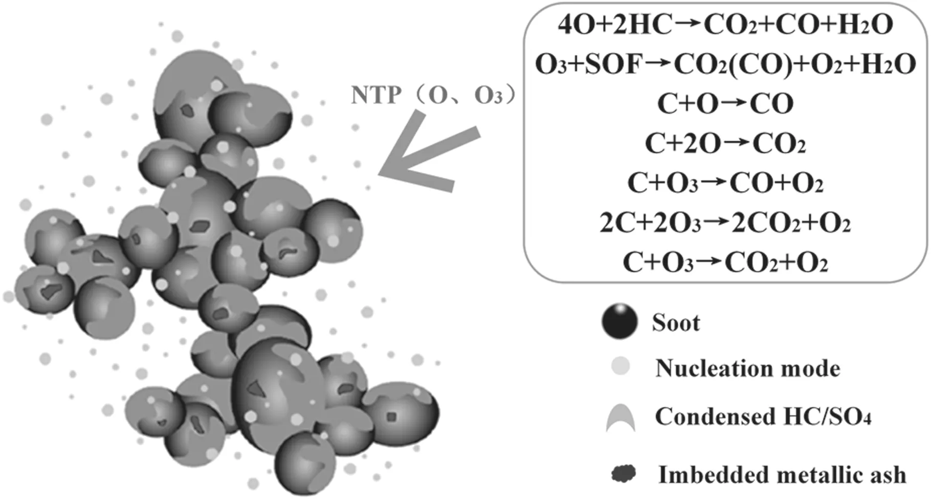
Figure 4.Chemical reaction model of the decomposition of PM mediated by reaction with NTP.
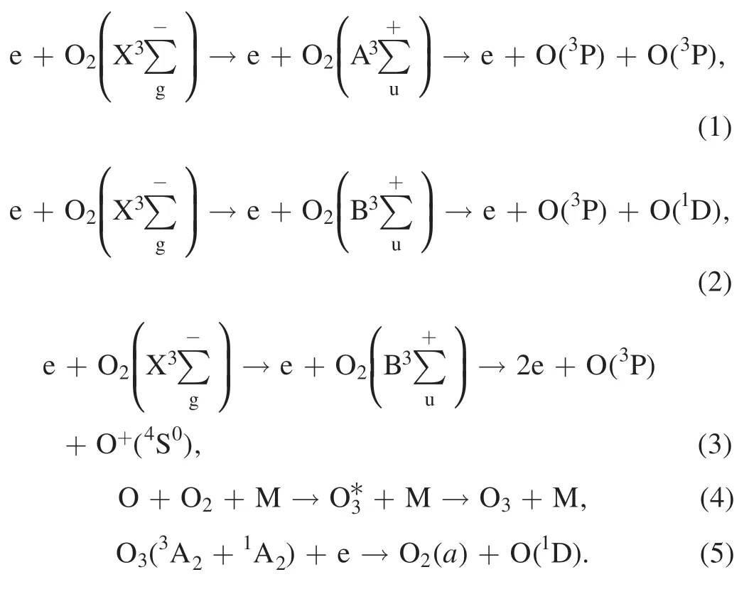
In the test,oxygen(99.99%)was used to regenerate DPF by NTP.A large number of active substances are produced after oxygen is discharged by dielectric barrier discharge in NTP reactors.NTP active substances react with PM in the DPF channel through electron impact excitation and dissociation to complete DPF regeneration.The main active substances involved in the decomposition of PM are O3and O.The chemical reaction equations of ionization,formation,and decomposition of oxygen and ozone molecules are shown in equations (1)–(5) [33–35]:
Diesel PM is a highly complex chain-shaped or flocculent aggregation.NTP active substances flow through DPF and react with PM; NTP active substances (e.g.O3,O) preferentially remove the SOF (SOF is composed of various alkanes,olefins,aromatics and organic impurities) on the surface of PM and then react with soot(in the center of PM).Imbedded metallic ash (mainly inorganic salts) cannot be removed by oxidation[30,36].The main reactions are shown in equations (6)–(12) [17,37,38]:
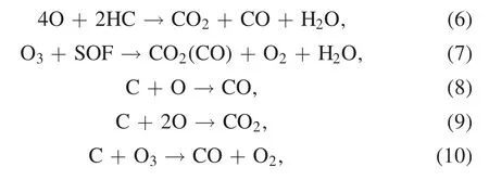
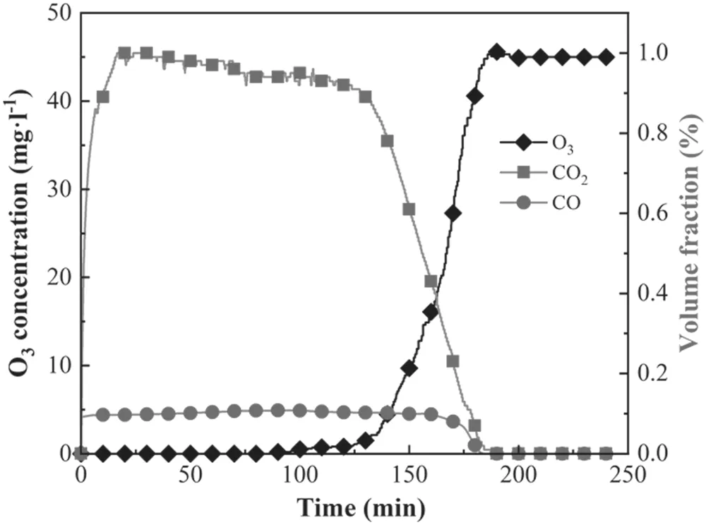
Figure 5.Variation in the outlet gas concentration during DPF regeneration using 75% load as an example.

As shown in equations (6)–(12),CO and CO2are the main final oxidation products,and O3plays an important role in PM oxidation [39].
Figure 5 shows variation in the outlet gas concentration during the DPF regeneration test (using 75% load as an example).In the initial stage of the DPF regeneration test,no ozone was detected at the outlet of DPF,and the volume fraction of CO2increased sharply compared with that of CO,which indicated that when NTP entered DPF,the PM immediately reacted with the active substances,and the active substances were consumed.After regeneration for about 25 min,the volume fraction of CO2was stable,and DPF entered a stable regeneration stage.After the regeneration reaction ran for 150 min,the volume fraction of CO2gradually decreased,and the O3concentration gradually increased.When the volume fraction of CO2and CO decreased to zero,indicating that there was no PM attached in DPF channels and the pore wall,NTP active gas could easily flow out of DPF,and the residual ash-PM fell off in DPF channels.The O3concentration at the outlet of DPF remained stable,and the O3concentration was 45 mg l−1,which was lower than that(65 mg l−1)in front of DPF.This stems from the self-decomposition effect of ozone.At this time,DPF has been regenerated [10].

Figure 6.Raman spectra of samples before and after NTP treatment.
3.2.Microstructure of residues in DPF channel
Figure 6 shows the Raman spectra of samples before and after NTP treatment.The first-order Raman spectrum of residues had two obvious peaks near the displacements of 1360 and 1580 cm−1(figure 6).The peak near the 1360 cm−1displacement corresponded to the respiratory vibration of graphite microcrystals,which was a defect peak that does not exist in ideal graphite (i.e.the D1 peak characterizing the disordered structure of carbon).The peak near the 1580 cm−1displacement was attributed to the stretching vibration of the C–C bond in the plane of the six-membered ring adjacent to the ideal graphite structure (i.e.the G peak) [40,41].Figure 7 shows the Raman spectrum peak fitting of samples before and after NTP treatment using 75% load as an example.The fivepeak fitting method was used before NTP treatment because there was no D2 peak in the samples near the 1620 cm−1displacement; after NTP treatment,the four-peak fitting method was used.Peak fitting was completed using Peakfit software.The D4,D2,D1 and G peaks were Lorentz peaks,and the D3 peak was a Gaussian peak.According to the Raman spectra fitting of ash,the intensity and the full width at half maximum (FWHM) of each peak can be obtained [42,43].
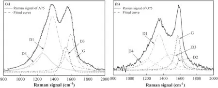
Figure 7.Schematic diagram of Raman spectrum peak fitting of samples before and after NTP treatment (using 75% load as an example).

Figure 8.The peak intensity ratio of ID1/IG and ID3/IG before and after NTP treatment.
Figure 8 shows the intensity ratio of the D1,D3 and G peaks of samples before and after NTP treatment.ID1,ID3andIGrepresent the integral intensity of the D1,D3 and G peaks,respectively.ID1/IGcan be used to characterize the degree of graphitization.HigherID1/IGcorresponds to lower degrees of graphitization of samples and higher degrees of disorder[42,44].ID3/IGis related to the content of amorphous carbon in the sample.HigherID3/IGcorresponds to higher amorphous carbon content in samples [45,46].Before NTP treatment,ID1/IGof PM samples increased as the engine load increased and ranged from 1.78 to 2.85.After NTP treatment,ID1/IGof ash-PM decreased compared with that before NTP treatment;it also decreased as the load increased from 1.5 to 1.8(figure 8).Higher loads corresponded to lowerID1/IG,indicating that the ordered graphite structure in the samples increased,the defect in the samples decreased,the degree of graphitization increased,and the ash-PM samples became more orderly.As the load increased,ID3/IGfirst increased and then remained stable,which was 0.47 at 25% load,0.55 at 50% load,0.5 at 75%load and 0.41 at 100%load.When the load increased,the maximum combustion temperature in the cylinder increased,which inhibited the formation of aliphatic and aromatic substances and reduced the content of amorphous carbon in the PM samples.After NTP treatment,ID3/IGincreased from 0.4 to 0.7 and decreased as the load increased.ID3/IGincreased the most at 25% load,and its value was 0.2 at 25% load.The content of carbon clusters and oxidation activity increased after NTP treatment [47].
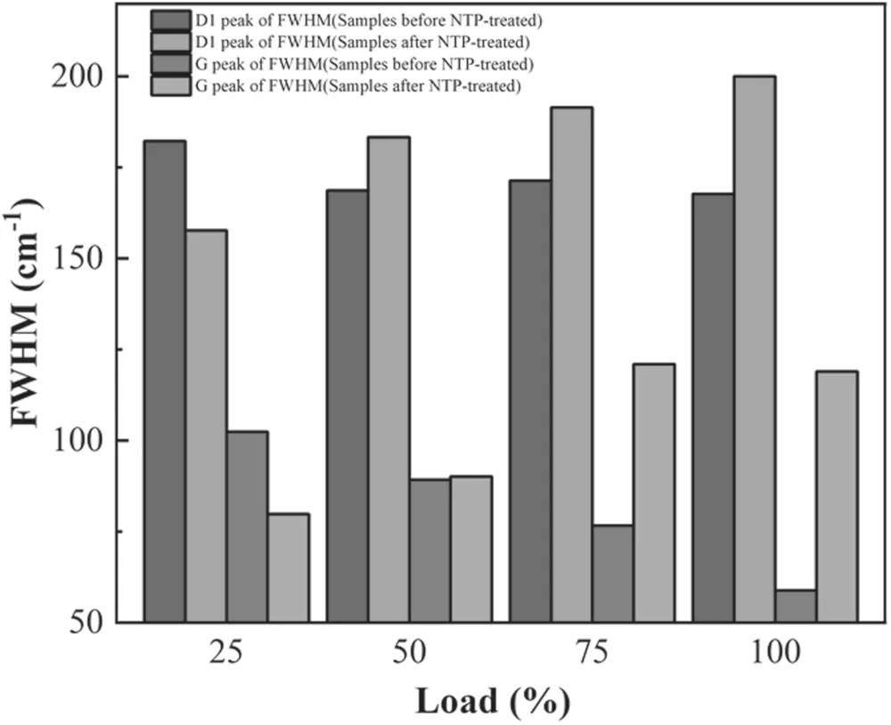
Figure 9.FWHM of the D1 and G peaks before and after NTP treatment.
FWHM is the difference between the Raman shifts of two points corresponding to the 1/2 peak intensity,which can be used to characterize the chemical heterogeneity of the sample,that is,the diversity of the crystal lattice structure in the sample[48,49].Figure 9 shows the FWHM of the D1 and G peaks of samples before and after NTP treatment.Before NTP treatment,the FWHM of the D1 peak of samples decreased as the load increased (figure 9).After NTP treatment,the FWHM of the D1 peak of samples increased from 157.7±3.1 cm−1to 200.0±3.7 cm−1,and the rate of increase slowed;the FWHM of the D1 peak of the same load(except 25% load) was higher than that of the PM samples.The change in FWHM of the G peak before and after NTP treatment was similar to that of FWHM in the D1 peak.The FWHM of the G peak of the PM samples decreased as the load increased from 102.4±8.72 cm−1(at 25% load) to 58.86±5.90 cm−1(at 100%load).After NTP treatment,the FWHM of the G peak of the samples decreased from 79.8±3.8 cm−1to 121.0±2.7 cm−1and then decreased slightly to 111.9±1.3 cm−1(100% load).The change in FWHM of the D1 and G peaks before and after NTP treatment indicated that the structural defects at the edge of the microcrystals and the carbon atoms in functional groups were oxidized by NTP active substances at low and medium loads;the FWHM of the D1 and G peaks decreased,and the chemical heterogeneity decreased.At medium and high loads,new free electrons were generated,and the molecular structure of microcrystals was reconstructed;the FWHM of the D1 and G peaks increased [50,51].
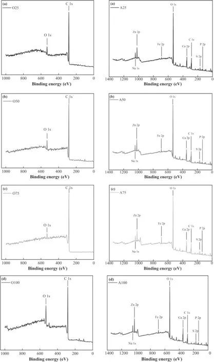
Figure 10.X-ray photoelectron spectroscopy of samples before and after NTP treatment.
3.3.Element occurrence state of residues in DPF channel
Figure 10 shows the XPS wide- scan spectrum of samples before and after NTP treatment.Clear element peaks were observed near 286 eV and 533 eV in the PM samples and the ash-PM samples,which corresponded to the C 1s and O 1s spectra,respectively (figure 10).In addition,there were clearly visible peaks near the peak positions of the 347 eV and 1022 eV bands in the ash-PM samples.The peaks of the 347 eV and 1022 eV bands were attributed to Ca 2p and Zn 2p,respectively.The C 1s and O 1s peaks were normalized because the C and O elements in PM samples were more significant compared with other elements before NTP treatment.As carbonaceous components continued to be removed after NTP treatment,the ash fell off from the polymerized structure of PM or shrank and fell off together with the remaining carbon,forming a carbon in ash structure.Therefore,in addition to the four obvious peaks mentioned above,identifiable peaks could also be observed in ash-PM samples near 130 eV,162 eV,710 eV and 1071 eV,which were attributed to P 2p,S 2p,Fe 2p and Na 1s,respectively.The pattern in the XPS wide-scan spectrum lines and the distribution of the peaks were basically the same for the samples before and after NTP treatment[52,53].Tables 3 and 4 show the calculated molar percentages of each element in PM samples and ash-PM samples before and after NTP treatment.Before NTP treatment,the main elements in the PM samples were C and O,and C accounted for more than 85.46%(table 3).DPF regeneration by NTP involves the continuous oxidation and decomposition of active substances[20],that is,the continuous removal of carbon atoms in DPF channels.Moreover,NTP reacted with granular sediments through the DPF channels,and the incorporation of NTP active substance(O atoms) into PM improved the diversity of oxygen-containing functional groups in ash-PM samples.Therefore,after NTP treatment,the molar percentage of C elements decreased; the molar percentage of O elements was higher than that of C elements,and the molar percentage of O elements was 43.64%–48.11%.The molar percentages of S and P elements were relatively high and were 2.98%–3.67% and 2.58%–3.24%,respectively.There were four main types of metal elements in the wide-scan spectrum:Na,Ca,Fe and Zn.The molar percentage of Ca was the highest,and the molar percentage of Ca was 9.16%–9.57%;the molar percentages of Na and Fe were lower (1.13%–1.23% and 1.31%–1.50%,respectively).The total molar percentage of the four metal elements Na,Ca,Fe and Zn in the ash-PM samples ranged from 13.96% to 14.67% (table 4).
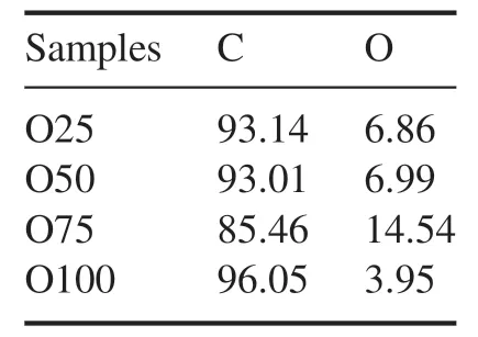
Table 3.Molar percentage of constituent elements in the samples before NTP treatment (%).
There were multiple sets of peaks in the XPS wide-scan spectrum,but the binding energy of photons excited by different elements differed.Therefore,a narrow-scan spectrum of C,O,and S elements was performed using XPS technology to analyze the occurrence state and the occurrence content of each element.Figure 11 shows the scanning curve of the carbon spectrum and the peak fitting results of samples before and after NTP treatment using 75% load as an example.The Gauss–Lorenz hybrid fitting method was used to fit spectrum peaks [54].
The carbon spectra of the samples under a 75%load were fitted according to the surface functional group types,and three peaks were obtained (figure 11).The peak positions of the bands were located at 285.8–288.7 eV,285.6–286.2 eV and 284.6–284.9 eV,which belong to O–C=O(carbonyl),C–OH (hydroxyl) and C–C,respectively.The area of each spectrum peak can be obtained by the peak fitting graph,and the area ratio of each spectrum peak can be obtained by comparing the area of each spectrum peak with the area of the carbon spectrum scanning curve.The peak area ratio is the percentage of the content of the functional group of the peak in the total content of the element,that is,the occurrence ratio[53].The molar percentage of each functional group in the sample can be calculated by the occurrence ratio.Table 5 shows the C 1s band peak position and molar percentage content of samples before and after NTP treatment.The C element in the samples was in the form of C–C,C–OH and O–C=O functional groups (table 5).In the PM samples,carbon atoms mainly existed in C–C,accounting for 76.48%–95.17%.The proportion of carbon atoms combined with two O atoms (O–C=O) was 1.81%–6.42%.The proportion of carbon atoms combined with one O atom (C–OH) was 3.02%–18.09%.As the load increased,the occurrence ratio of C–C functional groups decreased gradually,the occurrence ratio of C–OH and O–C=O functional groups increased,and the content of carbon atoms combined with O increased.In addition,there was a deterioration in fuel atomization,which made the collision and condensation frequency of the soot crystal nucleus increase [55],and more oxygen-containing functional groups were formed at the edge of the carbon microcrystals [56].After NTP treatment,the proportions of the O–C=O,C–OH,and C–C functional groups in the ash-PM samples were similar.The proportion of C–C was approximately 50%,the proportion of C–OH was 13.9%–15.9%,and the proportion of O–C=O was 33.8%–36.1%.The molar percentages of O–C=O,C–OH and C–C in the ash-PM samples decreased slightly as the load increased.For example,the molar percentages of C–C decreased from 18.32%to 15.47%.When the load increased from 25%to 75%,the molar percentages of C–OH and O–C=O decreased from 5.83% and 12.49% to 4.32% and 10.73%,respectively.Although the molar percentages of C–OH and O–C=O increased slightly to 4.46%and 11.28%,respectively,when the load increased to 100%,the molar percentages of C–OH and O–C=O in the ash-PM samples under 100% load were slightly lower than those under 25% and 50% loads.The occurrence proportion of C element in the form of the O–C=O functional group increased significantly after NTP treatment; the occurrence proportion of C element in the form of C–OH (except at 100% load) also increased,and the occurrence proportion of C element in the form of C–C decreased significantly.The decrease in the occurrence ratio of the C element also indicated that carbon atoms were continuously removed by NTP active substances during DPF regeneration (tables 3,4).Compared with inorganic salts and metal oxides,the occurrence form and content of combustible substances were the main reasons for variation in the chemical stability of the ash-PM samples; this indicated that O atoms in NTP were inserted into the residues,which led to an increase in oxygen-containing functional groups.
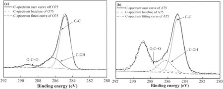
Figure 11.Carbon spectrum scanning curve and peak fitting of samples before and after NTP treatment using 75% load as an example.

Table 4.The molar percentage of the constituent elements of ash-PM samples (%).

Table 5.Peak position and molar percentage content of the C 1s band of samples before and after NTP treatment.
Table 6 shows the peak position and molar content of the O 1s band of the PM samples before NTP treatment.The main fitting range was 531.1–531.8 eV,which is attributed to the carbon–oxygen double bond;532.6–533.5 eV is attributed to the carbon–oxygen single bond of ether and hydroxyl groups [53].Approximately 60% of the O atoms in the samples combined with C atoms are in the form of C–O(table 6).As the load increased,the proportion of C=O in the PM samples was 2.32%,3.03%,5.26% and 1.26%,and the proportion of C–O was 4.54%,3.96%,9.28% and 2.69%.
Figure 12 shows the S-spectrum scanning curve and peak fitting results of the samples before and after NTP treatmentusing sample A75 as an example.Two peaks were obtained after peak fitting of the S-spectrum scanning curve of the ash sample(figure 12).The peak positions of the bands were 168.7 eV and 166.7 eV,which corresponded to SO42−(sulfate) and SO32−(sulfite),respectively.The S-spectrum scanning curves of the A50,A75 and A100 ash samples were basically consistent with that of the A25 ash sample.Table 7 shows the peak position and molar percentage content of the S 2p band of the ash sample obtained after peak fitting.The S element existed in the ash sample in the form of SO42−and SO32−,and the peak positions were located at 168.7–169.1 eV and 166.4–166.7 eV,respectively.As the diesel engine load increased,the proportion of S element in the form of SO42−in the regenerated ash increased,and the proportion of S element in the form of SO32−decreased.When the load increased from 25% to 100%,the occurrence ratio of SO42−increased from 37.9% to 42.3%,and the occurrence ratio of SO32−decreased from 61.7% to 57.4%; the occurrence ratio of SO32−was always higher than that of SO42−.The molar percentages of SO42−and SO32−tended to first increase and then decrease as the load increased,and both attained their highest values at 75% load; when the load increased from 25% to 100%,the molar percentage of SO42−increased from 1.13% to 1.53% and then decreased to 1.45%,and the molar percentage of SO32−increased from 1.84% to 2.14%and then decreased to 1.97%.The XPS narrow-scan and analysis results of S element in the ash sample showed that the S element existed in the ash in the form of sulfate and sulfite,and the proportion of sulfite (calculated as element S) was higherthan that of sulfate.As the load increased,the proportion of sulfite occurrence decreased,and the proportion of sulfate occurrence increased;the molar percentage of sulfite and sulfate attained their highest values in the A75 ash sample,indicating that the content of inorganic salts in the ash obtained from DPF regeneration at 75% load was higher.

Table 6.Peak position and molar percentage content of the O 1s band of samples before NTP treatment.
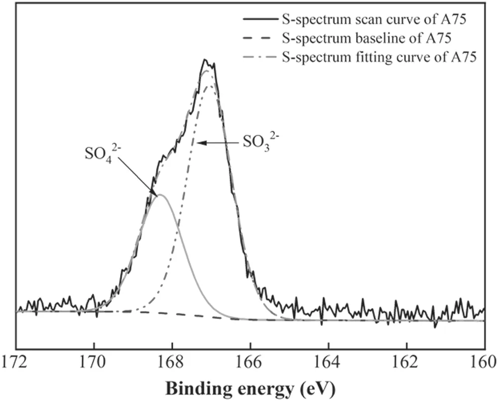
Figure 12.Sulfur spectrum scanning curve and fitting results of A75.

Table 7.Peak position and molar percentage content of the S 2p band of ash-PM samples.
According to the molar percentages of O–C=O,C–OH,SO42−and SO32−in tables 5 and 7,the molar percentages of O element in ash samples in the form of O–C=O,C–OH,SO42−and SO32−can be calculated (table 8).The molar percentage of the O element in the ash sample was between 43.64% and 48.11%,and the molar percentage of O in the two organic forms of O–C=O and C–OH was between 21.47% and 24.98% and between 4.32% and 5.83%,respectively.The molar percentage of O element in the two inorganic forms of SO42−and SO32−was 4.54%–6.13% and 5.53%–6.41%,respectively.The molar percentage of O elements in the form of O–C=O,C–OH,SO42−and SO32−was as high as 38.33%–40.88%,and 2.76%–9.78%in other forms in the ash samples.The molar percentage of SO42−and SO32−was only 2.98%–3.67%,which indicated that the molar percentage of metal elements in the form of sulfate and sulfite was less than 5%,and the total molar percentage of metal elements was relatively high,ranging from 13.96% to 14.67%.Therefore,2.76%–9.78% of O elements were combined with metal elements and existed in the form of metal oxides in the ash.
4.Conclusion
DPF with different loads was regenerated by an NTP injection device,and the residues (ash in carbon: PM and ash in ash:ash-PM)in the DPF channels before and after NTP treatmentwere sampled.Raman and XPS were used to investigate changes in the microstructure and element occurrence state of samples.The main results are detailed below.

Table 8.Occurrence form and molar percentage content of O element in ash-PM samples (%).
(1) NTP active substances (O3and O atoms) can oxidize and decompose PM in the DPF channel to complete DPF regeneration.NTP flows through DPF to preferentially remove the SOF on the surface of PM and then react with soot.Imbedded metallic ash cannot be removed by oxidation,and the residual ash-PM is formed in DPF channels.The O3concentration at the outlet of DPF was lower than that at the inlet of DPF because of the self-decomposition effect of ozone.
(2) As the load increased,ID1/IGof the PM samples increased,andID3/IGremained stable overall.After NTP treatment,ID1/IGof ash-PM samples was lower than that of PM samples,indicating that ash-PM samples were more ordered (i.e.defects were reduced,and the degree of graphitization was increased).ID3/IGof ash-PM samples was higher than that of PM samples,indicating that the content of amorphous carbon was increased,and the oxidation activity of ash-PM was higher.The change in FWHM of the D1 and G peaks before and after NTP treatment indicated that there was a mutual transformation between the structures of the samples.
(3) The main component of PM was C,and C atoms existed in the form of C–C,C–OH,and O–C=O functional groups.The content of O first increased as the load increased and decreased to 3.95% at 100%load; it mainly combined with C atoms in the form of C–O.DPF regeneration from NTP involves the continuous oxidation and decomposition of PM (i.e.the constant removal of carbon atoms).The occurrence ratio of the C element decreased,and other elements appeared.The total molar percentage of Ca,Na and other metal elements was 13.96%–14.67%; the molar percentage of S element was 2.98%–3.67%.S element occurred in the form of SO42−and SO32−.The addition of NTP into the DPF channel led to an increase in oxygen-containing functional groups,and the ash-PM samples were rich in chemical forms.In addition to SO42−and SO32−,some O elements were present in ash-PM in the form of metal oxides.
Acknowledgments
This work is currently supported by National Natural Science Foundation of China (No.51806085),China Postdoctoral Science Foundation (No.2018M642175),Jiangsu Planned Projects for Postdoctoral Research Fund (No.2018K101C),Open Research Subject of Key Laboratory of automotive measurement,control and safety (Xihua University) (No.QCCK2021-007) and Graduate Student Innovation Fund Project of Jiangsu Province (No.KYCX21_3354).
猜你喜欢
杂志排行
Plasma Science and Technology的其它文章
- Recent results of fusion triple product on EAST tokamak
- Suppression and mitigation of inter-ELM high-frequency Alfvén-like mode by resonant magnetic perturbation in EAST
- Simulations of NBI fast ion loss in the presence of toroidal field ripple on EAST
- Reconstructions of velocity distributions from fast-ion D-alpha (FIDA) measurements on EAST
- Tomography of emissivity for Doppler coherence imaging spectroscopy diagnostic in HL-2A
- Comparison of natural grassy ELM behavior in favorable/unfavorable Bt in EAST
