Simulations of NBI fast ion loss in the presence of toroidal field ripple on EAST
2021-09-10YingfengXU徐颖峰YoujunHU胡友俊XiaodongZHANG张晓东XingyuanXU徐行远LeiYE叶磊XiaotaoXIAO肖小涛andZhenZHENG郑振
Yingfeng XU (徐颖峰),Youjun HU (胡友俊),Xiaodong ZHANG (张晓东),Xingyuan XU (徐行远),4,Lei YE (叶磊),Xiaotao XIAO (肖小涛) and Zhen ZHENG (郑振),4
1 College of Science,Donghua University,Shanghai 201620,People's Republic of China
2 Member of Magnetic Confinement Fusion Research Centre,Ministry of Education,Donghua University,Shanghai 201620,People's Republic of China
3 Institute of Plasma Physics,Chinese Academy of Sciences,Hefei 230031,People's Republic of China
4 University of Science and Technology of China,Hefei 230026,People's Republic of China
Abstract NBI fast ion losses in the presence of the toroidal field ripple on EAST have been investigated by using the orbit code GYCAVA and the NBI code TGCO.The ripple effect was included in the upgraded version of the GYCAVA code.It is found that loss regions of NBI fast ions are mainly on the low field side near the edge in the presence of ripple.For co-current NBIs,the synergy effect of ripple and Coulomb collision on fast ion losses is dominant,and fast trapped ions located on the low field side are easily lost.The ripple well loss and the ripple stochastic loss of fast ions have been identified from the heat loads of co-current NBI fast ions.The ripple stochastic loss and the collisioninduced loss are much larger than the ripple well loss.Heat loads of lost fast ions are mainly localized on the right side of the radio frequency wave antennas from the inside view toward the first wall.For counter-current NBIs,the first orbit loss due to the magnetic drift is the dominant loss channel.In addition,fast ion loss fraction with ripple and collision for each NBI linearly increases with the effective charge number,which is related to the pitch angle scattering effect.
Keywords: fast ion loss,ripple,NBI,heat load,collision
1.Introduction
Fast particles play an important role in tokamak fusion plasmas.Fusion reaction can produce energetic alpha ions.Fast particles can also be produced by radio frequency wave(RFW) heating and neutral beam injection (NBI).Fast ion losses not only reduce the heating efficiency,but also destroy the first wall of tokamaks and produce impurities.
The discreteness of toroidal field coils destroys the axisymmetry of the tokamak.This toroidal asymmetric perturbation is called the toroidal field ripple.The toroidal field ripple can induce energetic or fast ion losses and may cause the localized heat load on the first wall,especially RFW antennas.The resulting heat load on the first wall limits the toroidal field ripple amplitude and the number of toroidal field coils in a tokamak fusion reactor.Simulations of energetic ion losses with the toroidal field ripple have been performed by using various orbit codes,such as OFMC [1,2],ORBIT [3],and VENUS-LEVIS[4].Ripple-induced losses of NBI fast ions have been studied experimentally and numerically in many tokamaks,such as JT-60U [5–7],JET [8,9],TFTR [10,11],and EAST [12,13].Previous simulations of the ripple loss on EAST were performed by using the orbit code ORBIT.The canonical variables used by ORBIT for computing the guiding-center orbits are based on the magnetic flux coordinates,in which the safety factor is singular at the X points.Therefore,the last closed flux surface (LCFS),instead of the first wall,was used as the outer/loss boundary in the previous ripple loss simulations on EAST.In addition,the 2D distributions of heat loads and loss regions have not been given in the previous ripple-induced fast ion loss simulations on EAST.
We have recently developed a Monte Carlo orbit-following code GYCAVA [14,15],which can be used for investigating the behavior of test particles in a tokamak.It is of interest to numerically investigate NBI ion losses and their 2D heat loads in the presence of ripple on EAST,with the first wall being the loss boundary by the GYCAVA code.
In this work,numerical simulations of NBI ion losses on EAST in the presence of the toroidal field ripple and collision by the orbit code GYCAVA and the NBI code TGCO are presented.The TGCO code has been benchmarked with the NBI code NUBEAM.The GYCAVA code has been integrated with TGCO[15].The toroidal field ripple effect has been added in the new version of the code GYCAVA.The cylindrical coordinates were used in our GYCAVA simulations for avoiding the problem of the singularity of the safety factor at the X points.The first wall without and with RFW antennas has been used as the outer boundary in our orbit simulations.The ripple and collision effects on fast ion behaviors of NBI ions on EAST have been studied.The TGCO code is used for computing the initial distribution of NBI ions,which is an input of the orbit-following code GYCAVA.Previous work on the ripple loss of NBI ions on JT-60U [5] has pointed out that the radial electric field has a small effect on the heat load position induced by ripple-trapped NBI ions.Therefore,the effect of the radial electric fieldErhas not been included in our simulations for simplicity.The radial electric field effect on fast ion losses will be investigated in future.
The remaining part of this paper is organized as follows.The equations of motion in the presence of toroidal field ripple and collision used in the GYCAVA code are presented in section 2.In section 3,the simulation setup,including the equilibrium of EAST,the plasma profiles,the birth distributions of NBI ions and the toroidal field ripple,is given.The numerical results of ripple- and collision-induced NBI ion losses on EAST are presented and discussed in section 4.Section 5 summarizes the main results.
2.Equations of motion in the presence of ripple and collision used in GYCAVA
For investigating the ripple effect on NBI ion losses,we have added the ripple effect in the new version of the GYCAVA code.The guiding-center equations of motion including the toroidal field ripple and the Coulomb collision used in GYCAVA are introduced as follows.
The axisymmetric equilibrium magnetic field for a tokamak can be expressed as

Here,ψ is the poloidal magnetic flux and φ is the toroidal angle.
The toroidal field ripple can be defined as
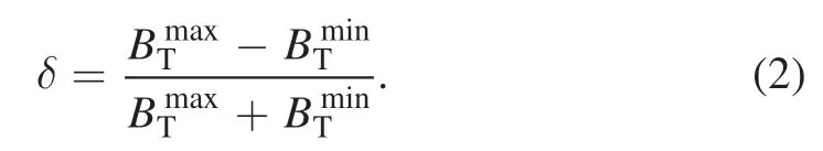
Here,BTminandBTmaxare the minimum and maximum values of the toroidal magnetic field which are computed at two points with the same radial and vertical positions,but different toroidal positions.Therefore,the magnitude of ripple δ is a function ofRandZ.
The ripple effect on fast ion losses,including the ripple well loss and the ripple stochastic loss,is mainly due to the toroidal component of the ripple field [16,17].Therefore,only the toroidal ripple field is kept in our GYCAVA code for simplicity.The magnetic field including toroidal field ripple isThe toroidal field perturbation related to the ripplecan be written as

We can see thatδBripis minimal whenfor the fixedRandZ.Here,Nis the number of the toroidal field coils.Then the total magnetic field can be written as

The guiding-center equations of motion including the toroidal field ripple can be written as

Here,Xis the guiding-center position of a charged particle andv‖is the parallel velocity.msandesare the mass and charge of the charged particles,respectively.B0.The guiding-center Hamiltonian is expressed as
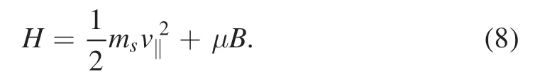
Note thatB≃B0+δBrip.
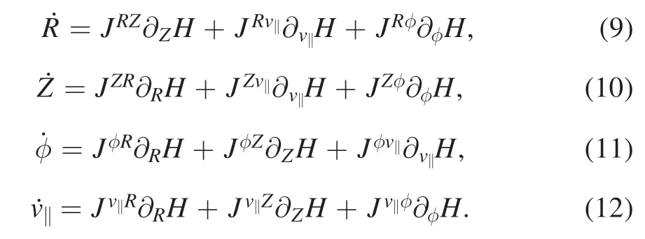
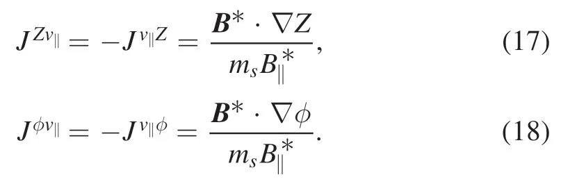
The guiding-center equations of motion (6),(7) can be explicitly expressed in terms of the Possion matrix and the cylindrical coordinates as

The guiding-center orbits were computed in GYCAVA simulations.However,the finite Larmor radius effect can impact the loss fractions [18] and the hit points [19] of fast ions.Therefore,the particle coordinates,which are obtained by the guiding-center transform from the guiding-center coordinates,are used for judging whether a fast ion is lost or not in GYCAVA.
The Coulomb collision of fast ions and background particles including the slowing down and the pitch angle scattering is contained in the GYCAVA code [15,20].The slowing down of fast ions due to electron and ion drag can be expressed as

Here,νsis the slowing down collision rate,written as

neis the electron density.eandefare the electron and fast ion electric charges,respectively.Zmis defined as=ZmThe subscriptjis the background ion species.Λln is the Coulomb logarithm.vcis the critical velocity,expressed as

Here,me,mfare the electron and fast ion masses,respectively.Teis the electron temperature.
The pitch angle scattering of fast ions is computed by a Monte Carlo method [21].The new pitch of particle,λnew,is computed from the old one,λold,by

Here,λ=v‖/vand Δtis the time step used in orbit simulations.νdis the pitch angle scattering rate,expressed as
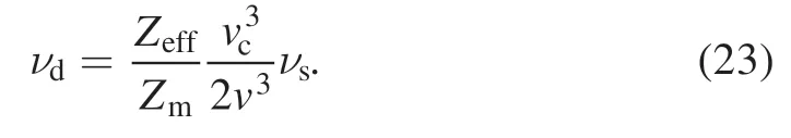
Here,Zeffis the effective charge number,defined asIn our simulations,the default effective charge number is chosen asZeff=2.The NBI fast ions and bulk ions on EAST are both deuterium.Therefore,Zm≃1.
3.Simulation setup
In this section,the magnetic configuration of EAST,plasma profiles,the birth distributions of fast ions produced by different NBIs,and the ripple field on EAST are presented.

Figure 1.The magnetic configuration (magenta line) and the shape of the first wall(black line)and the LCFS(blue line)on EAST.The red line denotes the shape of the RFW antennas.
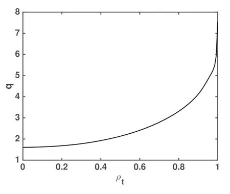
Figure 2.The safety factor profile for EAST discharge #62585.
The parameters of EAST discharge#62585 were used in our NBI ion loss simulations.The magnetic equilibrium configuration of this discharge and the first wall with the antennas of RFW are shown in figure 1.The direction of the plasma toroidal current is counter-clockwise from the top view,and the direction of the magnetic field is clockwise,which means that the magnetic drift direction of ions is downward.The major radius at the axis isRaxis=1.91 m and the minor radius isa=0.46 m.The magnetic field at the axis isBaxis=2.2 T and the plasma current isIp=0.56 MA.Figure 2 shows the safety factor profile.ρtdenotes the square root of the normalized toroidal magnetic flux.The range of the safety factor is 1.6–7.6 with the value at 95% of the poloidal magnetic flux isq95=4.8.The density and temperature profiles were used as inputs of the TGCO code for simulating the deposition of NBIs on EAST.Figure 3 shows the plasma profiles,including the electron density,the temperatures of electron and ion for EAST discharge#62585.The maximum electron density isne0=6.8 ×10¹⁹m−3.The maximum electron and ion temperatures areTe0=2.2 keV andTi0=2.3 keV,respectively.

Figure 3.The electron density (a),electron temperature (b) and ion temperature (c) profiles for EAST discharge #62585.
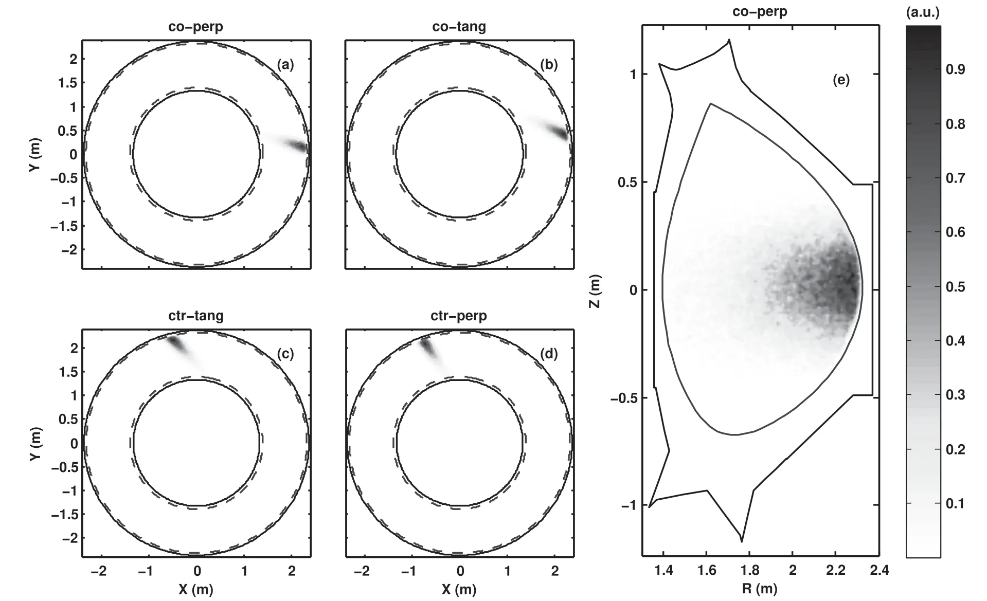
Figure 4.The initial spatial distributions of different NBI ions from the top view: (a) co-perp NBI,(b) co-tang NBI,(c) ctr-tang NBI,(d) ctr-perp NBI,and (e) the distribution for the co-perp NBI in the cross-section.
The parameters of NBIs used in our simulations were chosen as those of NBIs [13] on EAST.Four NBIs with different tangential radii were used in most simulations.Two NBIs are injected in the co-current direction,while the other two NBIs are in the counter-current direction.The tangent radii of the co-current tangential and perpendicular NBIs arerespectively.The tangent radii of the counter-current tangential and perpendicular NBIs are0.606 m,respectively.The full energy of beams are chosen asEb=50 keV in all cases of our simulations.The species of NBI ions is deuterium on EAST.NBI deposition on EAST is simulated by the NBI code TGCO.This code is used for computing the birth distributions of fast ions produced by four NBIs on EAST.Figure 4 shows the birth distributions of fast ions produced by NBIs.Figures 4(a)–(d) show the birth spatial distributions for four NBIs from the top view,respectively.Figure 4(e) shows the birth spatial distributions for the co-current perpendicular NBI in the poloidal crosssection.In fact,the spatial distributions for different NBIs in the poloidal cross-section are similar.
The ripple parameter δ can be fitted with an analytic function [13,22,23],expressed as

For the EAST tokamak,the coefficients related to the toroidal field ripple are chosen asN=16,δ0=1.267 ×10⁻⁴,Rrip=1.714 −0.181Z2,brip=0.267,wrip=0.149 m [12,13].Figure 5 shows the contour lines of the toroidal field ripple δ.The maximum value of the ripple δ within the LCFS is 0.76%.The position of maximal δ is located atR=2.32 m andZ=0.04 m,that is,the rightmost of the LCFS.
The poloidal cross-section of plasmas can be divided by the ripple well boundary[16]into two regions,the ripple well region and the reminder.The ripple well boundary is given by
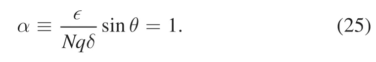
Here,∊is the inverse aspect ratio,that is,∊=r/R.ris the minor radius.θ is the geometric poloidal angle.The ripple well region is the plasma region with α<1,in which toroidal wells exist.The ripple well boundary for EAST is shown in figure 5.For the regions enclosed by the ripple well boundary,α>1 and toroidal wells do not exist.The plasma region outside the ripple well boundary is the ripple well region for EAST.In the ripple well region,fast ions with very small pitch can be trapped in the toroidal wells and then they are lost through the magnetic drift in the vertical direction.The loss positions of fast ions due to the ripple well loss are vertically above or below the ripple well region,which depends on the direction of the magnetic drift or the toroidal magnetic field.
4.Numerical results
Orbits of two trapped 50 keV fast ions in the EAST tokamak in the presence of the toroidal field ripple are shown in figure 6.From figure 6(a),we can see that the fast ion with the initial pitchv‖/v=0.2 finally hits the first wall near the mid-plane.This fast ion loss is due to the ripple stochastic loss[17].Ripple makes turning points of the fast trapped ion become stochastic.From figure 6(b),we can see that the fast ion with a very small pitch (v‖/v=0.05) finally hits the first wall vertically below the initial position of the fast ion.This fast ion loss is due to the ripple well loss,which is induced by the magnetic drift and the ripple well.The magnetic drift is downward in this case,and therefore the lost position is below the mid-plane.
In figures 7–10,fast ion loss simulations were performed in four cases: (i)without ripple and collision,(ii)with ripple,(iii) with collision and (iv) with collision and ripple.In these simulations,the 3D wall (the wall with RFW antennas) has been used as the outer boundary.The 3D wall used in GYCAVA includes two LHW antennas [24] and two ICRF antennas[25]on EAST.After the upgrade of EAST in 2020,LHW antennas are located at ports B and E of EAST,respectively.Two ICRF antennas are located at ports N and I,respectively.The parameter setup of RFW antennas in GYCAVA roughly agrees with that on EAST.
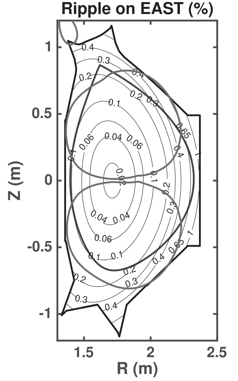
Figure 5.The contour plot(black)of the toroidal field ripple and the boundaries of the ripple well(red)on the EAST tokamak,as well as the shapes of the LCFS (blue) and the wall (black).
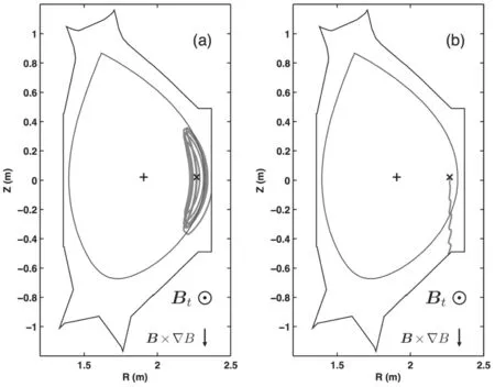
Figure 6.Orbits (red line) of two trapped 50 keV fast ions in the EAST tokamak in the presence of the toroidal field ripple with the initial pitch v‖/v=0.2 (a) and v‖/v=0.05 (b).The initial radial position is ˆψ = 0.8.Here,ˆψ is the normalized poloidal magnetic flux.The cross and plus symbols denote the initial position of a fast ion and the magnetic axis position,respectively.
The loss fraction at the final time computed from our simulations,which almost reaches a steady state,can represent the loss fraction of fast ions for continuous NBI,if the NBI ion source,full magnetic fields and plasma profiles remain unchanged.The heat loads computed from our simulations also represent the heat loads for continuous NBI.
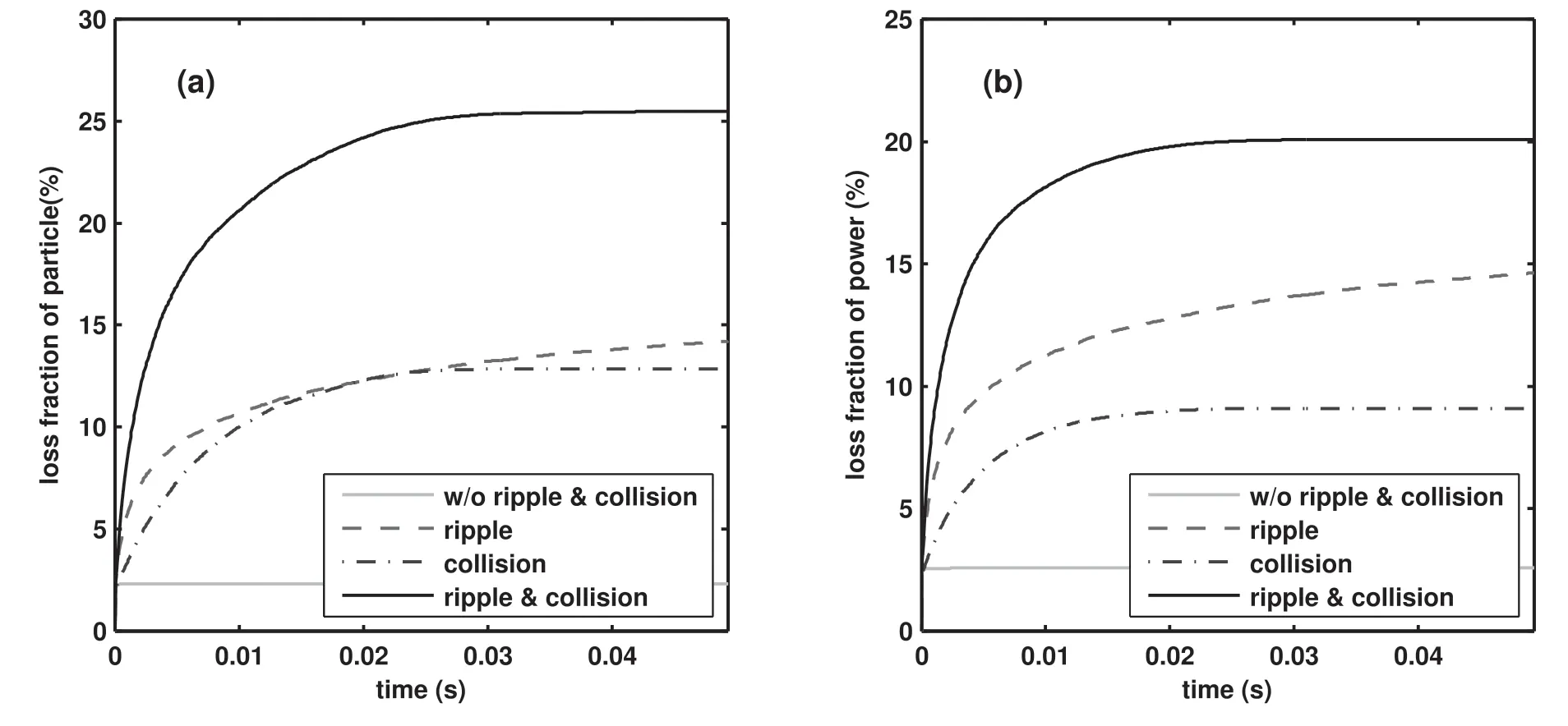
Figure 7.Time histories of particle (a) and power (b) loss of co-current perpendicular NBI fast ions in the four cases: without ripple and collision (cyan),with ripple (red),with collision (blue),with collision and ripple (black).

Figure 8.Time histories of particle(a)and power(b)loss of co-current tangential NBI fast ions in the four cases:without ripple and collision(cyan),with ripple (red),with collision (blue),with collision and ripple (black).
Time histories of particle and power loss fraction of cocurrent perpendicular(co-perp)and co-current tangential(cotang)NBI fast ions are shown in figures 7 and 8,respectively.We can see that the first orbit losses are small for co-perp and co-tang NBIs.In the cases with collision,fast ion loss increases with time at the early stage and reaches a steady state finally.The pitch angle scattering is responsible in collision-induced loss,especially for the co-perp NBI.In contrast to the co-tang NBI,the ripple-induced loss for the co-perp NBI is more significant.This is because trapped fast ions tend to lose due to ripple in contrast to passing fast ions,and the co-perp NBI produces more trapped ions than the co-tang NBI.The power loss with collision is smaller than the particle loss,which is due to the slowing down effect.
Time histories of particle and power loss fraction of counter-current tangential (ctr-tang) and counter-current perpendicular (ctr-perp) NBI fast ions are shown in figures 9 and 10,respectively.We find that the first orbit loss is very large for counter-current NBIs.The first orbit loss is 41%for ctr-tang NBI and 31% for ctr-perp NBI,respectively.This is because most NBI fast ions are deposited in the low field side in contrast to the high field side.The ripple-induced loss for the ctr-perp NBI is more significant than the ctr-tang NBI,which is similar to the result of co-current NBIs.In the cases with collision and ripple,fast ion loss for the ctr-tang NBI is similar to that for the ctr-perp NBI.The particle loss fraction is about 55% and the power loss fraction is about 50%.

Figure 9.Time histories of particle(a)and power(b)loss of counter-current tangential NBI ions in the four cases:without ripple and collision(cyan),with ripple (red),with collision (blue),with collision and ripple (black).

Figure 10.Time histories of particle (a) and power (b) loss of counter-current perpendicular NBI ions in the four cases: without ripple and collision (cyan),with ripple (red),with collision (blue),with collision and ripple (black).
We have also performed fast ion loss simulations with the 2D wall boundary.It is found that the fast ion loss with the 3D wall boundary is slightly larger than that with the 2D wall boundary.This is because the RFW antennas are included in the 3D wall boundary.
Birth distributions and striking positions of lost beam ions for different NBIs are shown in figures 11 and 12.In figure 11,ripple and collision have not been included and the 2D wall has been used as the outer boundary.Fast ion losses are only due to the first orbit loss.We can see that the loss region,that is,the birth distribution of lost beam ions,is determined by the NBI directions.Loss regions are on the high field side near the edge for co-current NBIs,while loss regions of beam ions are on the low field side for countercurrent NBIs.In figure 12,ripple and collision have been included and the 3D wall has been used as the outer boundary.We can find that loss regions for four different NBIs are mainly on the low field side.The differences of the loss regions shown in figures 11 and 12 are due to the fact that fast ion losses are enhanced by the synergy effect of ripple and collision.Ripple makes trapped fast ions easily lose and trapped fast ions are mainly on the low field side.Collisioninduced pitch angle scattering can enhance the ripple loss.The loss region with the 2D wall boundary is similar to that with the 3D wall boundary.However,final positions of lost fast ions are significantly affected by the RFW antennas.
The heat loads induced by lost NBI ions with ripple and collision for different NBIs are shown in figures 13–14.In figure 13,the 2D wall boundary has been used and the 3D wall boundary has been used in figure 14.
From figure 13,we can find that heat loads induced by lost NBI ions are on the first wall below the mid-plane and the lower divertor.The positions of these heat loads are affected by the magnetic field direction.The toroidal magnetic field used in our simulations is in the clockwise direction from the top view.This means that the magnetic drift direction of a fast ion is downward and thus lost fast ions hit the wall below the mid-plane.Heat loads for counter-current NBIs are much more significant than those for co-current NBIs.This is because the first orbit loss for counter-current NBIs is much larger,which is due to the fact that fast ions born on the low field side are much larger than those on the high field side.
From figures 13(a) and (b),we can see that most of heat loads are on the first wall near the mid-plane for co-current NBIs.These heat loads are mainly due to the synergy effect of ripple and collision.From figure 6(a),we know that the locations of these heat loads are the same as the striking points of lost trapped fast ions due to the ripple stochastic loss.In addition,the pitch angle scattering effect induced by collision can enhance the ripple stochastic loss significantly.Note that the effect of the first orbit loss on the heat load for co-current NBIs is small in contrast to the synergy effect of ripple and collision,which is shown in figure 7 and 8.Near θ=−60°(θ is the poloidal angle);we also can see that some of localized heat loads in the toroidal direction.From figure 6(b),we know that these heat loads are mainly due to the ripple well loss.The number of the localized heat loads near θ=−60°is the same as the number of the toroidal field coils,that is,N=16.Ripple well-induced losses are on the first wall vertically below the ripple well region.Fast ions with very small pitch,which are produced by collisioninduced pitch angle scattering,can be trapped in the toroidal wells.Then they are lost through the magnetic drift in the vertical direction.The fact that the loss position is below the Figure 11.Contours of birth distribution and striking positions(blue)of lost NBI ions in the absence of ripple and collision with the 2D wall boundary.Figure 12.Contours of birth distribution and striking positions(blue)of lost NBI ions in the presence of ripple and collision with the 3D wall boundary.mid-plane is also related to the fact that the magnetic drift is downward in our simulations.Ripple well loss is a rapid process.The timescale of the ripple well loss isa/vdwithvdthe magnetic drift.In contrast to the ripple well loss,the ripple stochastic loss and the collision-induced loss are dominant.

Figure 13.Heat loads induced by lost fast ions divided by the NBI injected power in the presence of ripple and collision with the 2D wall boundary.

Figure 14.Heat loads induced by lost fast ions divided by the NBI injected power in the presence of ripple and collision with the 3D wall boundary.
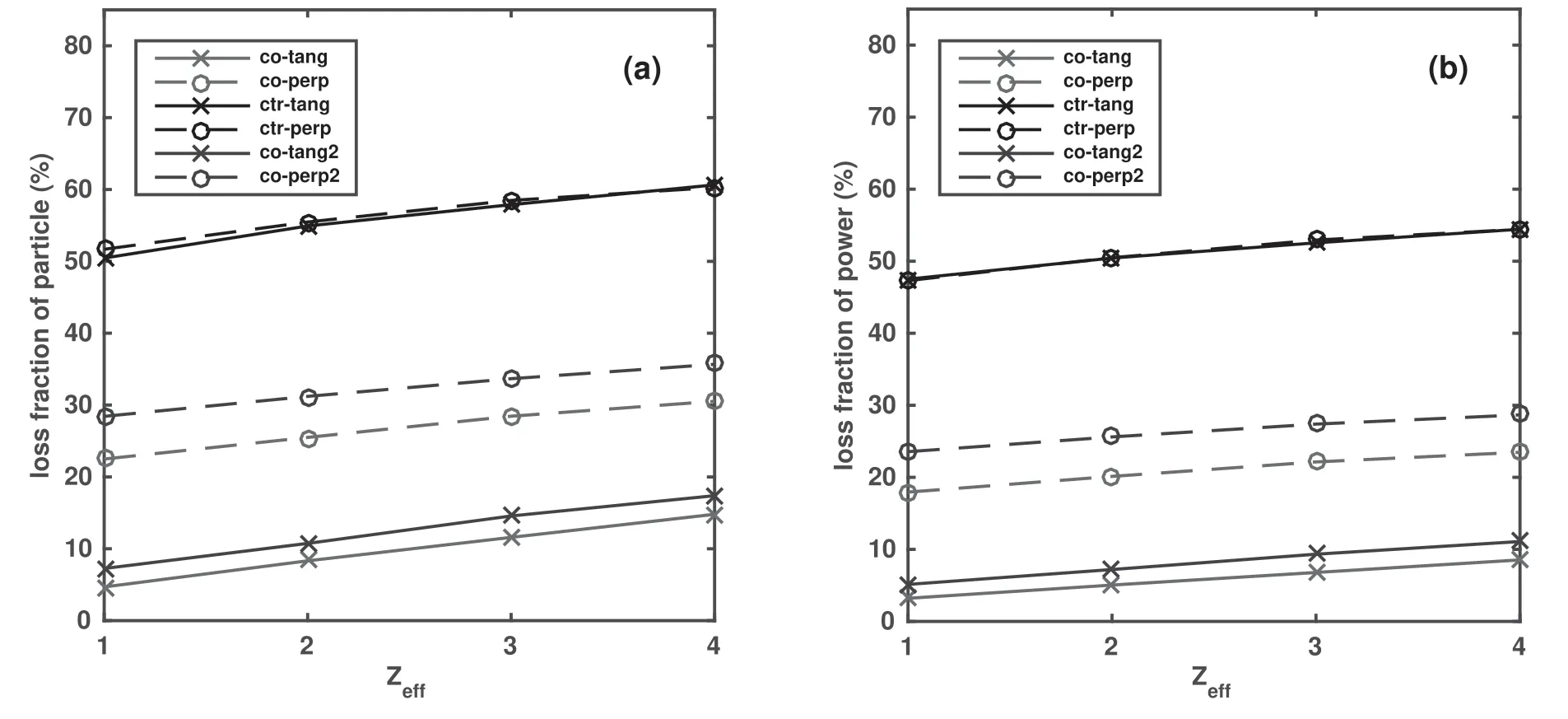
Figure 15.The particle and power loss fractions of fast ions as a function of the effective charge number for different NBIs in the presence of ripple and collision.
For counter-current NBIs,we find that heat loads induced by lost fast ions produced by tangential NBI are on the first wall below the mid-plane.For the tangential NBI,significant heat loads are on the lower divertor,which is shown in figure 13(c).Meanwhile heat loads of fast ions produced by the perpendicular NBI are mainly on the first wall near the mid-plane,which is shown in figure 13(d).These heat loads are due to the first orbit loss and the loss induced by ripple and collision.For counter-current NBIs,the effect of the first orbit loss on heat loads is dominant in contrast to the ripple and collision effects.
From figure 14,we can see that heat loads induced by lost fast ions near the mid-plane become more localized in contrast to figure 13,which is caused by the presence of the antennas of RFW.Heat loads are mainly located on the right side of all antennas of RFW from the inside view toward the first wall,especially on their edge.For co-current NBIs,heat loads are on the right side of all RFW antennas.Heat loads are mainly on the lower right corner of the ICRH2 antenna for ctr-tang NBI,while they are mainly on the lower right corner of the LHCD2 antenna for ctr-perp NBI.
The original counter-current NBIs on EAST will become the co-current NBIs after the upgrade of the EAST tokamak.The tangent radii of the new co-current tangential and perpendicular NBIs are0.606 m,respectively.Figure 15 shows the relation between the particle and power loss fractions of fast ions and the effective charge number for different NBIs in the presence of ripple and collision.The 3D wall boundary was used as the outer boundary.The simulation time for each case is about 50 ms so that the loss fraction can reach a steady state.It is found from figure 15 that the loss fractions of particle or power for each NBI linearly increase with the effective charge number.Note that the slowing down effect and the pitch angle scattering effect are included in the Coulomb collision.The slowing down effect is independent of the effective charge number,but the pitch angle scattering effect is proportional to the effective charge number.Therefore,the fast ion loss fractions induced by the effect of the pitch angle scattering increase with the effective charge number increasing.In contrast to the counter-current NBIs,the fast ion loss fractions of co-current NBIs are much smaller,especially for the cocurrent tangential NBIs.
5.Summary
NBI fast ion losses in the presence of the ripple field on the EAST tokamak have been simulated by the orbit-following code GYCAVA and the NBI code TGCO.The ripple effect was included in the new version of the orbit code GYCAVA.The walls without and with RFW antennas have been used as the outer or loss boundary in our orbit-following simulations.
The effects of the magnetic drift,ripple and Coulomb collision on fast ion losses of NBI have been investigated.Loss regions of fast ions are mainly on the low field side near the edge in the presence of ripple for all NBIs.For co-current NBIs,fast trapped ions located on the low field side near the edge are easily lost due to ripple and collision,and the NBI fast ion loss induced by the synergy effect of ripple and collision is the dominant loss channel.For counter-current NBIs,the first orbit loss is the dominant loss channel,and fast ions on the low field side near the edge tend to lose.
The ripple well loss and the ripple stochastic loss of fast ions have been identified from heat loads of fast ions for cocurrent NBIs.The lost fast ions due to the ripple well loss have very small pitch and they can be produced by the pitch angle scattering.The ripple stochastic loss and the collisioninduced loss are much larger than the ripple well loss.Heat loads induced by lost fast ions are mainly localized on the right side the RFW antennas with the wall including RFW antennas from the inside view toward the first wall.Heat loads for co-current NBIs are near the mid-plane,while heat loads for counter-current NBIs are on the lower right corner of RFW antennas and the lower divertor.
The loss fraction of particle or power with ripple and collision for each NBI linearly increases with the effective charge number increasing.This is due to the fact that the collision-induced pitch angle scattering effect is proportional to the effective charge number.
In this work,we focus on simulations of NBI ion losses with ripple.The simulation results will be compared with experimental observations on EAST in future.
Acknowledgments
The authors appreciate the support from the EAST team.Numerical simulations were performed on the ShenMa High Performance Computing Cluster in the Institute of Plasma Physics,Chinese Academy of Sciences.The work was supported by National Natural Science Foundation of China(No.11 775 265).
ORCID iDs
杂志排行

Plasma Science and Technology的其它文章
- Recent results of fusion triple product on EAST tokamak
- Suppression and mitigation of inter-ELM high-frequency Alfvén-like mode by resonant magnetic perturbation in EAST
- Reconstructions of velocity distributions from fast-ion D-alpha (FIDA) measurements on EAST
- Tomography of emissivity for Doppler coherence imaging spectroscopy diagnostic in HL-2A
- Comparison of natural grassy ELM behavior in favorable/unfavorable Bt in EAST
- The investigation of quasi coherent mode on EAST using Doppler reflectometry