传感器倾斜对于偏振光航向解算的影响
2021-07-02梁华驹白宏阳
梁华驹,白宏阳*,周 同,沈 凯
(1. 南京理工大学能源与动力工程学院,江苏南京210094;2. 南京理工大学机械工程学院,江苏南京210094;3. 北京理工大学自动化学院,北京100081)
1 Introduction
Traditional navigation systems such as the inertial navigation system,global position system(GPS), and geomagnetic navigation system(GNS)play a key role in the navigation of aircraft,robots,missiles,and vehicles. Inertial navigation systems have many advantages,whereas gyroscopes and accelerometers are usually prone to drift and noise,which may cause error accumulation over time[1]. In addition,although the GPS is a real-time and cost-effective locating system,GPS signals can be easily jammed owing to the presence of disturbances[2-3]. GNSs are sensitive to electromagnetic interference[4]. With the rapid advancement of human society,there is a need to design a highly precise,autonomous,reliable,and robust navigation system.
The navigation behavior of animals provides us with new ideas regarding navigation[5-6]. Desert ants rely on the predictable pattern of polarized light in the sky to find their way back home in hostile environments[7-8]. Honey bees detect the polarization of skylights to move from their hives[9-10].Birds use skylight polarization patterns to calibrate magnetic compasses during their long-range migrations[11]. The dorsal rim area of the compound eyes of locusts is sensitive to polarized skylight,enabling it to estimate its orientation[12-13].
These animals can use polarized light as a compass because of the polarization pattern in the sky[14-15]. Unpolarized sunlight through the Earth’s atmosphere produces a skylight polarization pattern[16-19]. Sunlight remains unpolarized until it interacts with atmospheric constituents,and scattering sunlight causes a partial linear pattern of polarization in the sky,which can be well described by the Rayleigh sky model[20-22].
Inspired by the polarization navigation behaviors of animals,several orientation-determination methods have been proposed based on the Rayleigh sky model. Polarization-orientation-determination methods mainly include the following four typical approaches:the zenith,solar meridian and antisolar meridian(SM-ASM),symmetry,and least-squares approaches. The zenith approach is based on calculating the heading angle by measuring the angle of polarization(AOP)at the sky zenith[3,16,23-25]. Because the polarization E-vector along the SM-ASM is consistently perpendicular to the SM-ASM,the heading angle can be calculated by extracting SM-ASM. This approach is called the SM-ASM approach[26-29]. Furthermore,because of the symmetry of the skylight polarization pattern,symmetry detection can be used to determine the orientation. This approach is termed the symmetry approach[30-32]. Finally,the polarization E-vector of the Rayleigh sky model is consistently perpendicular to the solar vector.Therefore,the orientation can be determined by the total-least-square method,which is called the least-square approach[33-36]. However, most of these heading-determination approaches require the polarization sensor to point toward the zenith of the sky dome[37]:the Zenith approach must directly capture the polarization information at the sky zenith;SM-ASM and symmetry approaches require that the reference direction of the AOP be converted to the local meridian using the sky zenith as a reference point;and the least-squares approach requires a known sky zenith dependent coordinate system to determine the orientation accurately.
In actual navigation,the carriers moving in three-dimensional space,such as aerial vehicles,aircraft,and rockets,tilt. Even carriers moving on the ground,such as vehicles and multilegged robots, tilt when the ground is uneven[38-39].Therefore,the impact of the polarization sensor tilt on bioinspired polarized skylight heading determination requires investigation and detailed discussion[15].
The objective of this paper is to study the impact of the sensor tilt on polarization orientation determination. First,a polarization compass simulation system is designed. Next,based on this simulation system,numerical simulation experiments are performed to investigate the impact of the sensor tilt on the aforementioned four classical heading-determination approaches. Finally,the results of the field experiments are compared with the results of the digital simulation to validate our conclusions.
2 Polarization simulation system
A polarization compass simulation system,depicted in Fig. 1,was designed to study the impact of the sensor tilt on orientation determination.
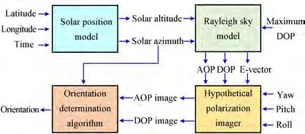
Fig. 1 Polarization compass simulation system. AOP is the angle of polarization,DOP is the degree of polarization,and E-vector is the polarization electric field vector
In addition,the sun azimuth coordinate frame was constructed to describe this system. As depicted in Fig. 2,oxg yg zgis the East-North-Up(ENU)geographic coordinate frame. Theyaaxis of the sun azimuth coordinate frameoxa ya zais aligned with the solar azimuth,zaaxis points to the zenith,andxaaxis completes the right-handed coordinate frame. The sun azimuth coordinate frame rotates around thezaaxis when the solar azimuth changes,and the direction of theyaaxis is always aligned with the direction of the solar azimuth.
The rotation matrix from the ENU coordinate to the sun azimuth coordinate is given by
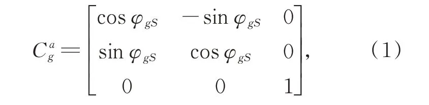
whereφgSis the solar azimuth angle in the ENU coordinate.
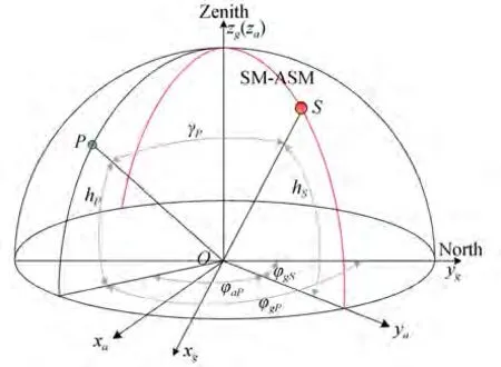
Fig. 2 Coordinate frame:oxg yg zg is the East-North-Up(ENU)geography coordinate frame. oxa ya zais the sun azimuth coordinate frame. Red circle S represents the sun. Green circle P represents the observation point. The red line SM-ASM represents the solar meridian and anti-solar meridian.hS is the solar altitude angle. hP is the altitude angle of P. γP is the angle between P and the sun.φgS is the solar azimuth angle,and φgP is the azimuth angle of P in the ENU coordinate. φaP is the azimuth angle of P in the sun azimuth coordinate
2.1 Solar position model
In this section,the solar position is calculated by the relevant astronomical formulae[40-43]to compare the simulation results and field experiments.
Based on relevant astronomical formulae,the position of the sun can be calculated using three angles:solar declination angleδS,solar hour angleTS,and latitudeLOof the observation site. Solving the spherical triangleS-O-NPin Fig.3,the solar altitude anglehS∈[0°,90°] and solar azimuth angleφgS∈[0°,360°] in the ENU coordinate frame are given by
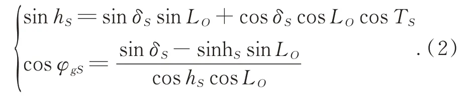
By solving the inverse trigonometric function in Eq. (2)and making quadrant judgments,we have:
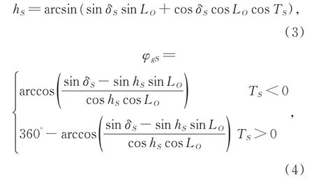
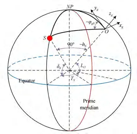
Fig. 3 Celestial sphere,where red circle S is the sun,O is the observation site,NP is the North Pole. δS is the solar declination angle,TS is the solar hour angle,LO is the latitude of the observation site,hS is the solar altitude angle and φgS is the solar azimuth angle in the ENU coordinate
where the formula for the solar declination angleδSfor 1985 is given by

where the day angleσS=2π(D-D0)/365.2422,Dis the day of the year,and the spring-equinox timeD0expressed in days from the particular year(1985)is
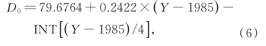
whereYis the year and INT represents the rounding down.
The calculation process for the solar hour angleTSis given below,where the local standard timeSdof the observation site can be calculated as

In Eq. (7),for observation siteO,SOandFOare the hour and minute of the Beijing time,respectively,andLonOis the longitude of observation siteO.
Then,time errorEtis given as:

Next,Sdis corrected byEtto obtain solar timeSt:

Finally,the solar hour angleTSis given as:

In short,using the above formulae,the solar azimuth angle and solar altitude angle can be calculated.
2.2 Rayleigh sky model
The Rayleigh sky model predicts the degree of polarization(DOP)of the sky polarization properties[3]as:
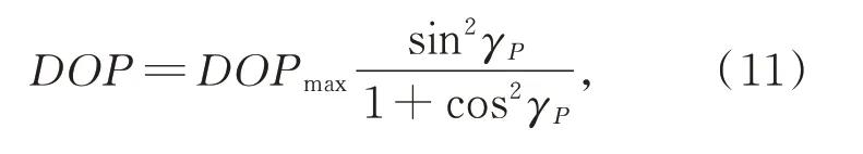
whereγP,called the scattering angle,is the angle between observation pointPand the sun.DOPmaxis the maximum detected DOP in the sky andDOPmax=1 for an ideal sky.
The Rayleigh sky model predicts the sky polarization properties AOP[26]as
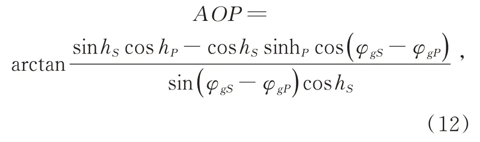
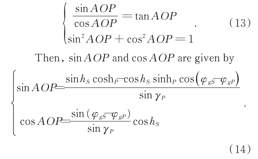
wherehPis the altitude angle of observation pointP,φgPis the azimuth angle ofPin the ENU coordinate,andAOP∈(-90,90). According to trigonometric functions,
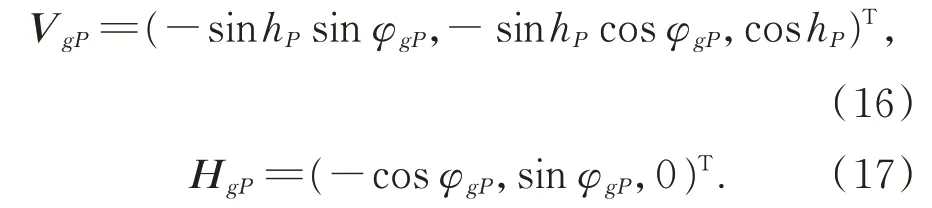
The sky polarization E-vector in the ENU coordinate predicted by the Rayleigh sky model is given as

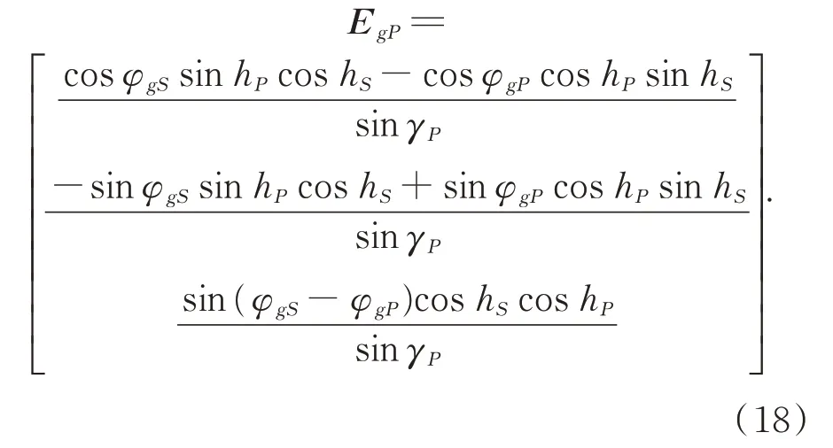
whereEgPis the polarization E-vector of observation pointPin the ENU coordinate predicted,VgPis the tangent direction of the local meridian,andHgPis the vector perpendicular toVgPand parallel to theoxg ygplane.VgPcosAOPandHgPsinAOPare the projections of the polarization E-vector onVgPandHgP,respectively:
The superscriptTrepresents a matrix or a vector transpose. Substituting(14)into(15),EgPin the ENU coordinate is given as
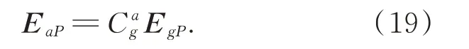
In short,the polarizationE-vectorEaPin the sun azimuth coordinate can be expressed as
2.3 Hypothetical polarization imager
To construct an ideal simulation system,both the skylight polarization model and the polarization imaging sensor must be constructed[37]. In this section,a hypothetical polarization imager is designed and described in detail.
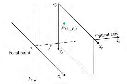
Fig. 4 Camera coordinate frame oc xc yc zc and pixel coordinate frame op xp yp,where f is focal length
To construct a hypothetical polarization imager,camera and pixel coordinate frames were established,as depicted in Fig. 4. Thezcaxis of the camera coordinate frameoc xc yc zcwas aligned with the optical axis of the imager,and thexcandycaxes of the camera coordinate frameoc xc yc zcwere aligned with the column and row directions of the image,respectively. Thexpandypaxes of the pixel coordinate frameop xp ypwere aligned with the column and row directions of the image,respectively. The unit of this coordinate is pixels.
In the camera coordinate frame,the vector of pixelP′(xpP′,ypP′)is
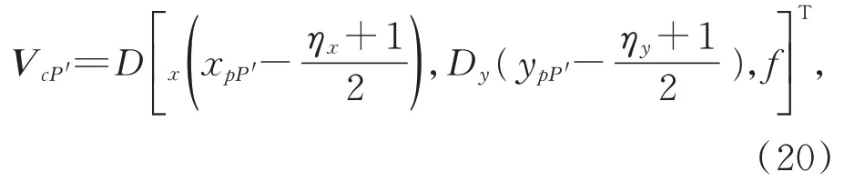
whereDxandDyare the column and row pixel sizes,respectively,ηxandηyindicate that the polarization image hasηx×ηypixels,andfis the focal length of the pixel-based polarization camera used.
Suppose three Euler angles of the polarization imager are given. Then the rotation matrix from the camera coordinate to the sun azimuth coordinate can be described as
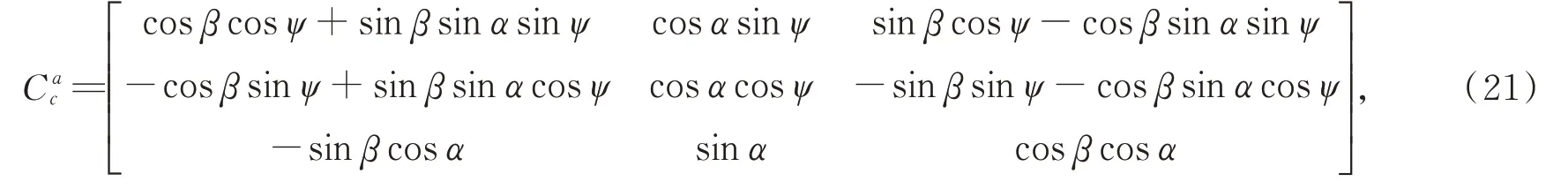
whereψ,α,andβrepresent the yaw,pitch,and roll angle,respectively.
Then,the shooting direction of pixelP′in the sun azimuth coordinate is
Azimuth angleφaP′of the shooting direction of pixelP′in the sun azimuth coordinate is
Altitude anglehP′of the shooting direction of pixelP′is

whereVaP′(1,1),VaP′(2,1),andVaP′(3,1) are the components ofVaP′,and|VaP′| is the mode ofVaP′. Then,the scattering angleγP′of the pixelP′is given as
Substituting Eq. (25)into Eq. (11),the DOP of pixelP′ can be obtained. Fig. 5(a)depicts a hypothetical DOP image.
The azimuth angleφgP′of the shooting direction of pixelP′in the ENU coordinate is

Therefore,substituting Eqs. (24),(26),and(18)into Eq.(19),the polarization E-vectorEaP′of pixelP′in the sun azimuth coordinate frame can be obtained. The polarization E-vectorEcP′ofP′in the camera coordinate frame can be given by
whereis the transpose of,which represents the rotation matrix from the sun azimuth coordinate to the camera coordinate. Because the AOP reference direction is aligned with theybaxis and the shooting direction of the hypothetical polarization imager is aligned with thezcaxis,the AOP can be calculated as
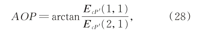
whereEcP′(1,1)andEcP′(2,1) are the components ofEcP′. A hypothetical AOP image is depicted in Fig. 5(b).
For the four typical orientation-determination algorithms described in Section 1,the zenith and least-squares approaches can directly use the AOP for orientation determination. However,for the SM-ASM and symmetry approaches, further transformation of AOP is required. The reference direction of AOP must be converted to the local meridian. The AOP whose reference direction is local meridian can be defined as

whereξis the angle between theycaxis and the local meridian. When the polarization imager points to the sky zenith,we have
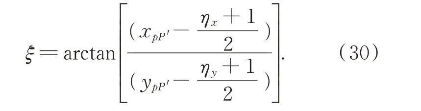
A hypothetical AOPLM image is obtained and depicted in Fig. 5(c).
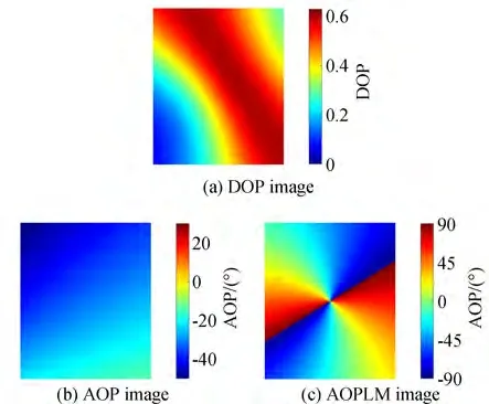
Fig. 5 Hypothetical polarization images
3 Simulation
To investigate the impact of the sensor tilt on orientation determination,we performed some simulation experiments for four classical polarizationorientation-determination algorithms,namely,the zenith,SM-ASM,symmetry,and least-squares approaches,as depicted in Fig. 6. According to the Rayleigh sky model,the polarizationE-vector at the sky zenith is perpendicular to the solar azimuth;therefore,the zenith approach determines the heading angle by measuring the AOP at the sky zenith[3,16,23-25]. The polarization E-vector along the SM-ASM is always perpendicular to SM-ASM. Therefore,the SM-ASM approach can be used to calculate the heading angle by extracting SM-ASM[26-29]. Using the symmetry of the skylight polarization pattern,the symmetry approach can determine the orientation by symmetry detection[30-32]. The polarizationE-vector of the Rayleigh sky model is always perpendicular to the solar vector;therefore,the least-squares approach can be used to determine the orientation by the total least square of the polarizationE-vectors[33-35].
Considering that the polarization imager needs to capture the skylight polarization pattern,the imager field of view must always be above the horizon,and the interference of buildings and obstacles must be eliminated. In our simulation and experiment,the imager angle of view was 108°;therefore,we set the pitch and roll angles to |α|+|β|≤30°.
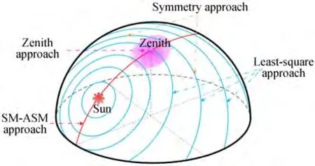
Fig. 6 Rayleigh sky model and four typical orientationdetermination approaches(The red dot represents the sun,the pink point represents the sky zenith,red line represents the solar meridian and anti-solar meridian(SM-ASM),blue lines represent the polarization electric field vectors(E-vector))
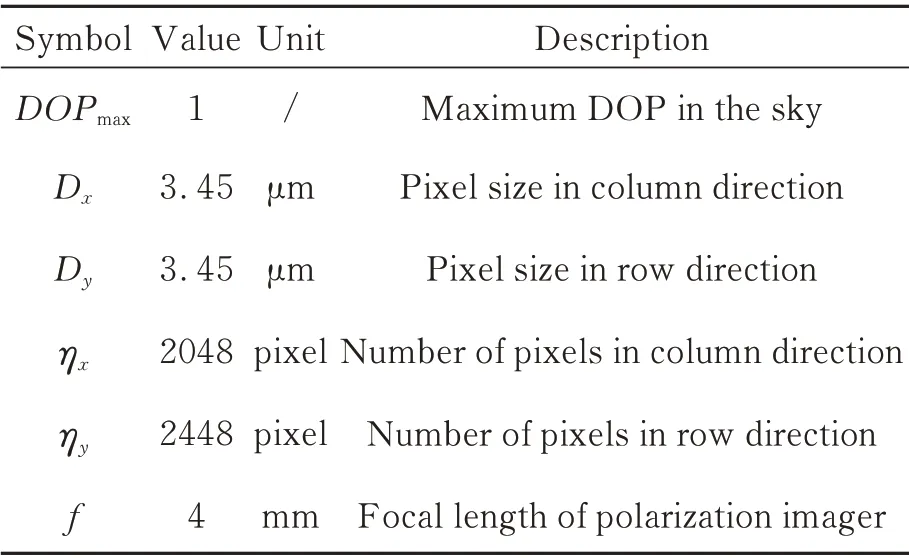
Tab.1 Simulation parameters
The tilt state of the sensor in practice can be divided into three situations:
1)Pitch-tilt-only condition
2)Roll-tilt-only condition
3)Pitch-and-roll-tilt condition
The parameters of the simulation are listed in Tab. 1.
3.1 Pitch-tilt-only condition
In this section,we discuss the error characteristics of the pitch-angle-only condition with the roll angle set to zero. Using the polarization compass simulation system discussed in Section 2,more than 1.4× 10⁵sets of simulation experiments were performed,and the orientation errors of four typical approaches were obtained in the ranges of solar altitude anglehS∈[0°,50°],yaw angleψ∈[-180°,180°],pitch angle,α∈[-30°,30°],and roll angleβ=0°. The results of the pitch-tilt-only condition are depicted in Fig. 7.
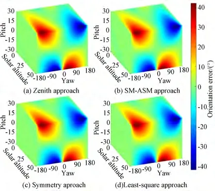
Fig. 7 Orientation errors of four typical polarization-orientation-determination approaches under pitch tilt
It can be observed in Fig. 7 that under the pitch-tilt-only condition,the variation trend of the orientation error for the four typical approaches is the same. There were three similarities:
(a)When the pitch angle was 0°,the error in all four approaches was close to 0. With an increase in the pitch angle,the error tended to increase.
(b)When the solar altitude angle was 0°,the error in all the four approaches was always close to 0°. When the pitch angle was not 0°,the error in all approaches tended to increase with an increase in the solar altitude angle.
(c)The error in the four approaches is symmetric with respect to planesψ=0° andψ=180°(-180°). When the yaw angle was 0° or 180°(-180°),regardless of the pitch and solar altitude angles,the error in all the four typical approaches were always close to zero. In addition,the following trends were observed:error was close to zero atψ=-180°. With the yaw angle increasing gradually,the error increased gradually and reached a maximum before the error decreased and approached zero atψ=0°. Subsequently,with the yaw angle increasing gradually,the orientation calculating error increased gradually and reached a maximum. Finally,the orientation error decreased and was close to zero atψ=180°.
The following is a detailed analysis of the reasons for the above three similarities:
For(a),whenα=0°,there is no impact of the sensor tilt. In other words,under ideal conditions,all four typical approaches can effectively determine the orientation. When the pitch tilt increases,the tilt interference increases,which leads to an increase in orientation-determination errors.
For(b),the four approaches essentially use the solar azimuth information to determine the orientation. When the solar altitude angle increases,the component of the solar vector projected on the planeoxa ya(oxg yg) decreases,thus the stability and reliability of the solar azimuth are weakened.This causes an increase in orientation-determination errors.
For(c),the errors in the four approaches are all symmetric with respect to planesψ=0° andψ=180°(-180°). This manifests in the symmetry of the skylight polarization pattern with respect to SM-ASM. When the yaw angle is 0° or 180°(-180°)and only pitch tilt occurs,the direction of the polarization imager′s optical axis always points to SM-ASM,which is parallel to theycaxis.Therefore,when the yaw angle is 0° or 180°(-180°),regardless of the pitch and solar altitude angles,the errors in the four approaches are always close to zero.
To further compare these four approaches,we drew groups of simulation results of the four approaches on a graph,as depicted in Figs. 8 and 9. It is evident that the variation trends of the four error curves are identical,and the four curves almost coincide. Furthermore,under similar conditions,the error difference between these four approaches is always less than 0.66°. Therefore,when there is interference from only the pitch tilt,it can be concluded that the error characteristics of the four approaches are consistent,and the orientation errors of the four approaches are almost the same. Moreover,similarity(b)is evident in Fig. 8,and similarities(a)and(c)can be partially reflected in Fig. 9.
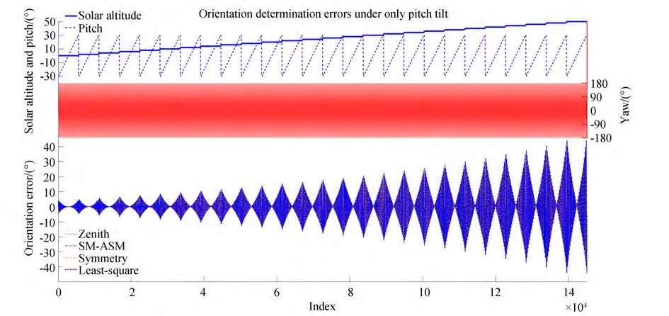
Fig. 8 Simulated orientation-determination error curves of four typical polarization-orientation-determination approaches under the pitch-tilt-only condition
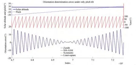
Fig. 9 Simulated orientation-determination error curves of four typical approaches under the pitch-tilt-only situation. This is an enlarged view of Fig. 8
3.2 Roll-tilt-only condition
In this section,we discuss the error characteristics for the situations when only the roll angle tilt exists and with the pitch angle set to zero. The orientation errors in four typical approaches were obtained in the ranges of the solar altitude anglehS∈[0°,50°],yaw angleψ∈[-180°,180°],roll angle,β∈[-30°,30°],and pitch angleα=0°.The results under this condition are depicted in Fig. 10,where the yaw range is [-180°,180°].For ease of observation and comparison,the range of yaw is converted to [-90°,270°],as depicted in Fig. 11. By comparing Figs. 11 and 7,it is evident that the two sets of graphs have identical shapes,with the only difference being the range of the yaw angle. Therefore,the error characteristics of the roll-tilt-only condition are significantly similar to those of the pitch-tilt-only condition. The first two error similarities are the same as those described in Section 3.1;however,the third one is different.
For only roll tilt,the errors in the four approaches were all symmetric with respect to planesψ=-90°(270°) andψ=90°. When the yaw angle was 90° or -90°(270°),regardless of the roll and solar altitude angles,the errors of the four typical approaches were always close to zero.We observed the following trends:the error was close to zero atψ=-90°,and with the yaw angle increasing gradually,the error increased gradually and reached a maximum. Subsequently,the error decreased and was close to zero atψ=90°.Then,as the yaw angle increased gradually,the error increased gradually and reached a maximum.Finally,the error decreased and was close to zero atψ=270°.
In short,compared with the result of the pitch-tilt-only condition,the result of the roll-tiltonly case has a 90° shift in the yaw direction. The reason for this phenomenon is given in below.
As depicted in Fig. 4,the direction of the optical axis of the polarization imager is (0,0,1)T.Using Eq.(22),the optical axis direction in the sun azimuth coordinate is given by
Assume two sets of altitudes (ψ1,α1,β1) and(ψ2,α2,β2) that satisfyψ2=ψ1+90°,β2=α1,β1=0°,andα2=0°.
whereVaf1andVaf2are the optical axis directions at(ψ1,α1,β1)and(ψ2,α2,β2)in the sun azimuth coordinate system,respectively.Vaf1=Vaf2indicates that the optical axis directions of the image at (ψ1,α1,β1) and (ψ2,α2,β2) are identical. Therefore,the polarization information collected by the polarization imager at (ψ1,α1,β1) and (ψ2,α2,β2)corresponds to almost the same area of the sky.As such,the results of the roll-tilt-only condition have a 90° shift in the yaw direction compared with that of the pitch-tilt-only condition.
To further compare these four approaches under the roll-tilt-only condition, we obtained groups of simulation results of the four approaches on a graph,as depicted in Figs. 12 and 13. It is evident that the variation trends of the four error curves are identical,and the four curves almost coincide. Furthermore,as depicted in Fig. 13,the error curve of the pitch-tilt-only condition is drawn for comparison with that of the roll-tilt-only condition. It is evident that the results of the roll-tilt-only condition have a 90° shift in the yaw direction compared with that of the pitch-tilt-only condition. Therefore,the properties of the roll-tilt-only condition can be obtained from that of the pitchtilt-only condition.
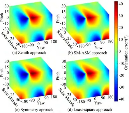
Fig. 10 Orientation-determination errors in four typical polarization-orientation-determination approaches under the roll-tilt-only condition with ψ ∈[-180°,180°]
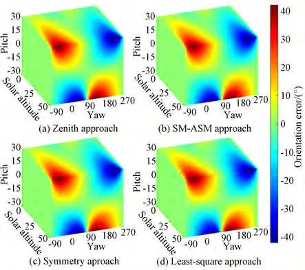
Fig. 11 Orientation-determination errors in four typical polarization-orientation-determination approaches under the roll-tilt-only condition with ψ ∈[-90°,270°]
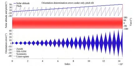
Fig. 12 Simulated orientation-determination error curves of four typical polarization-orientation-determination approaches under the roll tilt only situation
3.3 Pitch-and-roll-tilt condition
The error characteristics of the pitch-and-rolltilt condition are discussed in this section. The orientation-determination errors of four typical approaches were obtained in the ranges of the solar altitude anglehS∈[0°,50°], yaw angleψ∈[-180°,180°],pitch angleα∈[-30°,30°],roll angle,β∈[-30°,30°],and |α|+|β|≤30°.The results of the zenith approach for pitch and roll tilts are depicted in Fig. 14.
It is evident from Fig. 14 that under the pitch-and-roll-tilt condition the error in the zenith approach has the following characteristics:
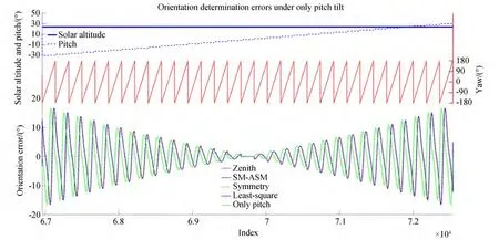
Fig. 13 Simulated orientation-determination error curves of four typical approaches under the roll tilt only situation. This is an enlarged view of Fig. 12. Only pitch is the error curve when the pitch angle equals the roll angle under the pitch-tilt-only situation
(a)With an increase in pitch and roll angles,the error in the zenith approach tends to increase.
(b)When the solar altitude angle was 0°,the orientation error in the zenith approach was close to 0°. When the pitch and roll angles were not 0°,the error tended to increase with an increase in the solar altitude angle.
(c) When the other conditions were the same,the yaw angle difference also affected the orientation errors.
The reasons for these observations are identical to those mentioned in Section 3.1. The following is a detailed analysis of the reasons for these three characteristics.
For(a),when the pitch and roll tilts increase,the tilt interference increases,which leads to an increase in orientation errors.
For(b),the zenith approach essentially uses solar azimuth information to determine the orientation. When the solar altitude angle increases,the component of the solar vector projected on the planeoxa ya(oxg yg)decreases,thereby weakening the stability and reliability of the solar azimuth.This leads to an increase in the orientation error.
For(c),with different yaw angles,the relative position between the sun and the polarization sensor is different,resulting in different orientation errors when the sensor tilts.
Under pitch and roll tilts,the error difference between the four approaches was always less than 0.77°. Therefore,the error characteristics of the other three approaches were consistent with those of the zenith approach.
3.4 Application values
The findings of this study have two important application:(1)Given the allowable error range of the orientation,the allowable range of the corresponding pitch and roll angles can be obtained.(2)The error caused by the sensor tilt can be corrected when the pitch angle and roll angle are given.
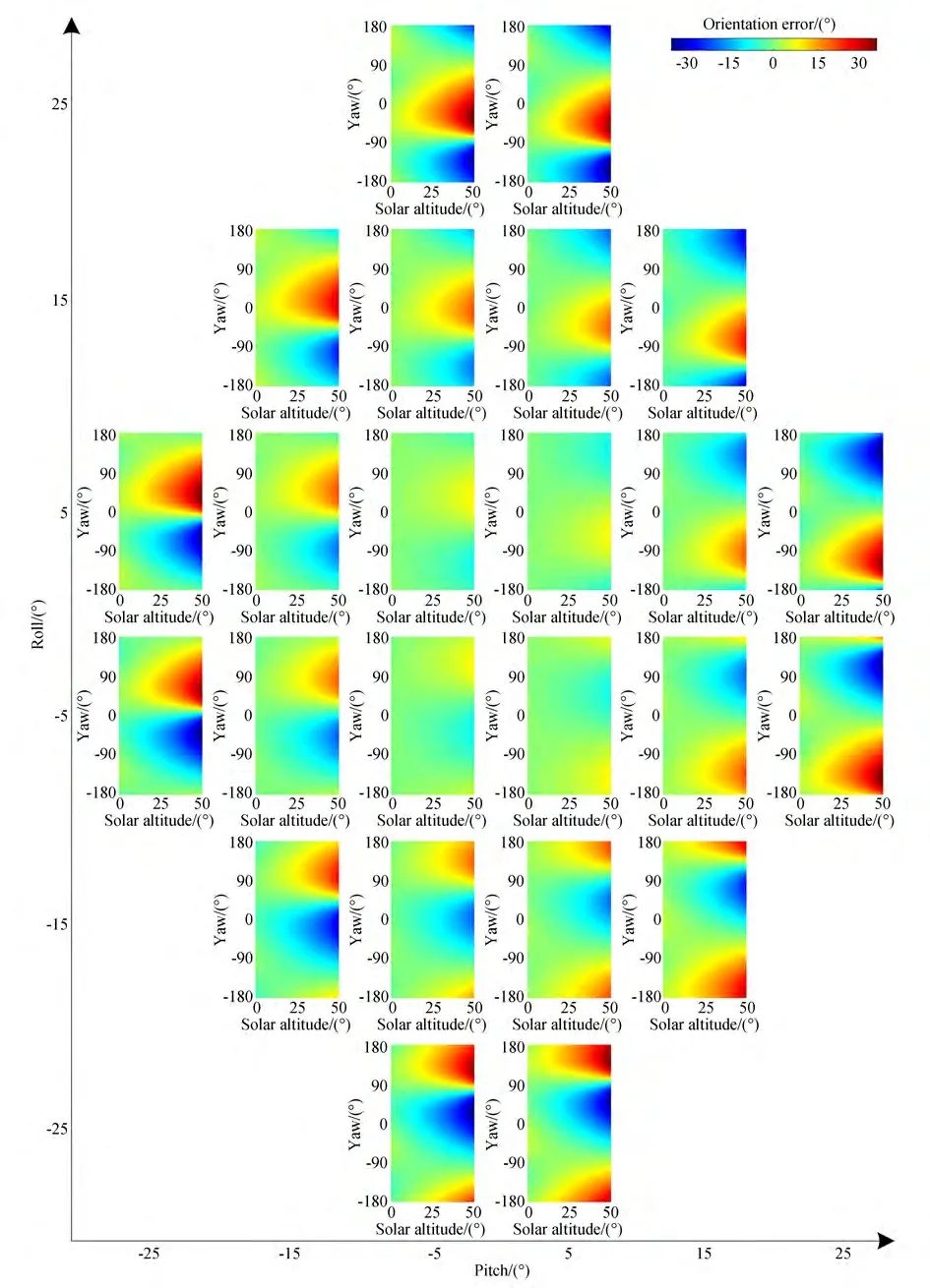
Fig. 14 Simulated orientation-determination error of the zenith approach under the pitch-and-roll-tilt condition
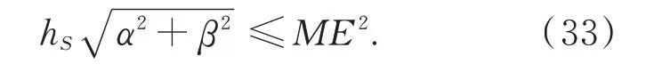
The allowable ranges of the pitch and roll angles are illustrated by considering the allowable maximum error of orientation as an example. Suppose that the maximum allowable error of orientation isME. It is important to note that for any yaw angle,the maximum error of orientation is affected not only by the pitch and roll angles but also by the solar altitude angle. When the pitch and roll angles are 0°,the orientation-determination error caused by the sensor tilt is 0°. When the pitch or roll angle increases,the maximum error in the orientation determination increases. When the solar altitude angle is 0°,the orientation-determination error is almost unaffected by the sensor tilt.When the solar altitude angle increases,the maximum error of the orientation determination increases. Based on the simulation results,the allowable ranges of the pitch and roll angles can be roughly estimated by
The results of this study can mitigate such orientation-determination errors. The impact of the sensor tilt is a type of system error,and a method of eliminating this error is to fully analyze its characteristics. Therefore,given the pitch angle and roll angle,the error caused by the tilt can be obtained based on the results of this study. Subsequently,the orientation can be calibrated by subtracting this error. In our field experiment,we mitigated such orientation-determination errors,as discussed in Section 4.
4 Field experiment
To further verify the simulation results,field experiments were performed to investigate the impact of the polarization sensor tilt on orientation determination. The results of the field experiments were compared with those of the simulation.
The experimental platform used in this study is depicted in Fig. 15. Two tripods were equipped with a Sony IMX250MZR polarization imager and a GPS/IMU(global position system/inertial measurement units)integrated navigation system. The parameters of the actual polarization imager were consistent with those of the hypothetical polarization imager,as listed in Table 1. The GPS/IMU integrated navigation system was used to determine the pitch and roll angles of the polarization imager. The true North was determined by a double-antenna GPS device as a benchmark(the orientation resolution was 0.1° with a 2 m baseline). Field experiments were performed in Nanjing, China, on the roof of our laboratory(32°0136.4″N,118°5111.9″E),between November 15 and November 19,2019. Meteorological conditions were stable. Fig. 16 depicts a set of actual polarization images.
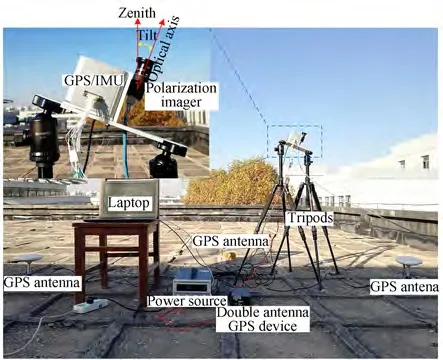
Fig. 15 Polarization-orientation-determination experiment platform
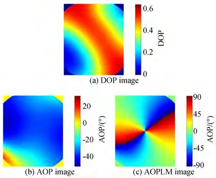
Fig. 16 Actual polarization images(The four corners of these polarization images could not be properly imaged owing to the short focal lens used in the imager. Therefore,these are not used in polarized skylight navigation and are set to 0)
To determine the impact of the sensor tilt,field experiments were performed for the pitch-tiltonly,roll-tilt-only,and pitch-and-roll-tilt conditions. The experimental results are depicted in
Figs. 17-19. The green curves in these figures depict the simulation results. As discussed in Section 3,the orientation errors in the simulation results of the four typical approaches were almost identical. Therefore,only one curve is drawn here to facilitate the observation and comparison of the simulation and experimental results. The dithering of the experimental orientation error curves is attributed to cloud interference,which was not the focus of this study.
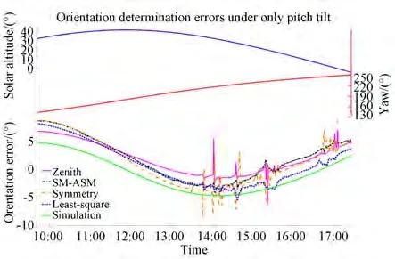
Fig. 17 Field experiment for the pitch-tilt-only condition on 15 November 2019 with pitch angle of-20.0°
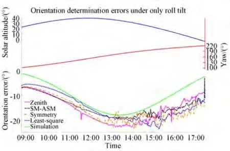
Fig. 18 Field experiment for the roll-tilt-only condition on 16 November 2019 with roll angle of 29.1°
As is evident in Figs. 17-19 from comparing the simulation results with the experimental results of the four typical approaches,it is clear that:(a)There are some differences between the simulation results and the field experimental results. However, these differences are always within a narrow range.(b)The experimental error curves and simulation error curves have the same variation trend,and the experimental errors in the four typical approaches have the same variation trend.
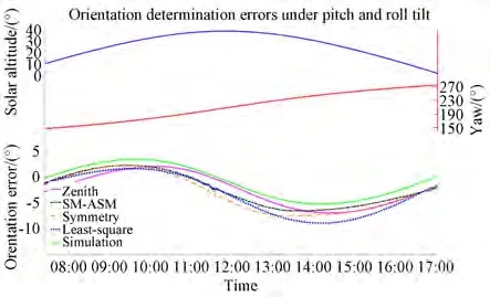
Fig. 19 Field experiment for the pitch-and-roll-tilt condition on 19 November 2019 with pitch and roll angles of-16.3°and -9.9°,respectively
For further analysis,in(a)of the above paragraph,the Rayleigh sky model is an ideal model that only considers a single scattering event and has some differences from the actual skylight polarization pattern[44]. Therefore,the experimental error curves did not coincide with the simulation error curves.
For(b)of the above paragraph,for all the pitch-tilt-only,roll-tilt-only,and pitch-and-rolltilt conditions,the orientation error curves of the field experiments and simulation had the same variation,and the experimental errors in the four typical approaches had the same variation trend.These results further indicate that the orientation error characteristics of the four typical approaches are consistent under the tilt interference. The simulation error curves of the four typical approaches almost coincided. However,the field experiment error curves of the four typical approaches did not coincide because field experiments were affected by not only sensor tilts but some other disturbances as well,such as measurement noise and clouds. In particular,where the curve wobbles markedly,orientation determination was disturbed by clouds.
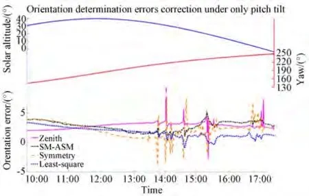
Fig. 20 Orientation-determination error correction for the pitch-tilt-only condition on 15 November 2019 with pitch angle of -20.0°
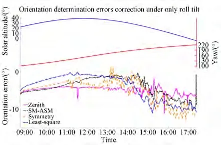
Fig. 21 Orientation-determination error correction for the roll-tilt-only condition on 16 November 2019 with roll angle of 29.1°
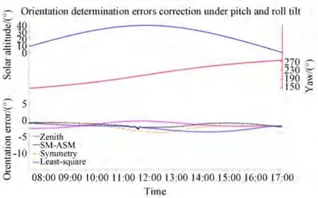
Fig. 22 Orientation-determination error correction for the pitch-and-roll-tilt condition on 19 November 2019 with pitch and roll angles of -16.3°and -9.9°,respectively
As depicted in Figs. 20-22,the results of this study can be used to correct the orientation-determination errors caused by sensor tilts. In particular,when the weather was good,the error correction result was better,as depicted in Fig. 22.However,when the weather conditions were complex and there was interference from clouds,this had some effect on error correction. However,the effect was negligible,as depicted in Figs. 20 and,particularly,in Fig. 21. This is because,when the weather is clear,skylight polarization patterns are closer to the Rayleigh sky model,and there is less interference from meteorological factors such as clouds. However,when the weather conditions are complex,skylight polarization patterns deviate from the Rayleigh sky model,and there is strong interference from meteorological factors,resulting in a poor correction effect.
4 Conclusion
In this study,the impact of the sensor tilt on polarized skylight orientation determination was investigated in detail. Four typical polarization orientation-determination approaches were described and compared with for three different conditions:the pitch-tilt-only,roll-tilt-only,and pitch-androll-tilt condition. Simulations based on the Rayleigh sky model indicated that the error characteristics of the four approaches were completely consistent,and the error curves almost coincided when it was only affected by the sensor tilt. With an increase in the tilt and solar altitude,the orientation errors in the four approaches tended to increase.The orientation errors were also affected by the yaw angle. Field experiments suggested that the errors in the four approaches exhibited the same variation trend. These results provide an important reference for the practical application of polarization orientation determination,particularly for the installation error of the sensor,the tilt of the application platform,and the change in the threedimensional attitude of the carrier.
The results of this study can also mitigate orientation-determination errors caused by sensor tilts and estimate the allowable ranges of the pitch and roll angles when given the allowable error of orientation determination.
The impact of the sensor tilt was investigated in detail using simulations and experiments. The results indicate that polarization orientation determination is not only affected by the sensor tilt but also by the measurement noise and clouds. Therefore,eliminating these impacts for orientation determination will be the focus of our future research.