Adaptive Pseudo Inverse Control for a Class of Nonlinear Asymmetric and Saturated Nonlinear Hysteretic Systems
2021-04-13XiuyuZhangMemberIEEERuijingJingZhiweiLiZhiLiMemberIEEEXinkaiChenSeniorMemberIEEEandChunYiSuSeniorMemberIEEE
Xiuyu Zhang, Member, IEEE, Ruijing Jing, Zhiwei Li, Zhi Li, Member, IEEE,Xinkai Chen, Senior Member, IEEE, and Chun-Yi Su, Senior Member, IEEE
Abstract—This paper aims at eliminating the asymmetric and saturated hysteresis nonlinearities by designing hysteresis pseudo inverse compensator and robust adaptive dynamic surface control(DSC) scheme. The “pseudo inverse” means that an on-line calculation mechanism of approximate control signal is developed by applying a searching method to the designed temporary control signal where the true control signal is included. The main contributions are summarized as: 1) to our best knowledge, it is the first time to compensate the asymmetric and saturated hysteresis by using hysteresis pseudo inverse compensator because the construction of the true saturated-type hysteresis inverse model is very difficult; 2) by designing the saturated-type hysteresis pseudo inverse compensator, the construction of true explicit hysteresis inverse and the identifications of its corresponding unknown parameters are not required when dealing with the saturated-type hysteresis; 3) by combining DSC technique with the tracking error transformed function, the“explosion of complexity” problem in backstepping method is overcome and the prespecified tracking performance is achieved.Analysis of stability and experimental results on the hardware-inloop platform illustrate the effectiveness of the proposed adaptive pseudo inverse control scheme.
I. INTRODUCTION
SMART-MATERIAL based actuators such as piezoelectric ceramics, magnetostrictive, ionic polymer-metal composites (IPMCs) and shaped memory alloys are widely used in high precision metal cutting systems, ferromagnetic and superconductive fields [1], [2]. When the input signal passes through the smart-material based actuators, the hysteresis loops are formed between the input signal and the output signal [3], [4]. The hysteresis loops possess the properties of multi-valuables, non-smooth and nonlinearity and their shapes will be changed with different frequencies and amplitudes of input signals. The existence of the hysteresis leads to the inaccurate, oscillated even instable problem of the control systems [5]. Also, in most cases such as magnetostrictive actuator and shaped memory alloys, the hysteresis nonlinearities are asymmetric and exhibit the saturated property, which makes the constructions of their corresponding inverse models become difficult. Therefore,with wide utilizations of smart-material based actuators, the effective inverse-compensation control scheme of the asymmetric and saturated type hysteresis nonlinearity receives much attention.
Generally, there are two methods to deal with the hysteresis inputs of nonlinear systems. The first one is to mitigate the hysteresis by establishing an inverse or estimated inverse hysteresis compensator (refer to [5]–[11]), then cascade it into the control system. For example, In [12], a new expression of the Krasnoselskii-Pokrovskii (KP) model is proposed, and the inverse of the KP model is constructed using the inverse multiplicative structure (IMS) method. In [13], an adaptive estimated inverse output-feedback quantized control scheme is proposed for the piezoelectric positioning stage, and the hysteresis nonlinearity in the piezoelectric actuator is mitigated by constructing the estimated hysteresis inverse compensator. In [14], the hysteresis in complex hysteresis nonlinear systems is weakened by constructing an inverse model of KP hysteresis. Through [12]–[15] we can know that the hysteresis phenomenon in the system can be compensated by constructing the hysteresis inversion method, but the construction of the inverse model itself is very complicated,and it is extremely difficult or even impossible to establish the hysteresis model in some complex nonlinear systems. The second one is to degrade the negative influence of hysteresis to the control performance by designing the robust adaptive control algorithms where the hysteresis is divided into linear part with respect to control input and nonlinear part with respect to hysteresis operator such as Prandtl-Ishilinskii (PI)hysteresis model. For example, in [16], a robust adaptive neural network control algorithm for solving generalized PI hysteresis in pure feedback stochastic nonlinear systems is studied. In [17], a robust adaptive control algorithm based on sliding mode is studied for dealing with hysteresis problems in nonlinear systems. In [18], a robust adaptive output feedback control scheme based on dynamic surface is proposed to solve nonlinear systems with unknown hysteresis. In [19], a robust adaptive neural network control method is proposed for a class of time-varying delay systems with backlash-like hysteresis input to deal with hysteresis in the system. In [20],an adaptive dynamic surface robust control method for metal cutting with hysteresis input is introduced. However, this method is not the true compensation of hysteresis because the nonlinear part is only treated as the external disturbance and the methods of dealing with hysteresis are the same as that of dealing with disturbances [21], [22].
Differently from the above two categories control scheme,in this paper, a hysteresis pseudo inverse compensator is developed for the high-precision control of continuous-time nonlinear systems with asymmetric and saturated hysteresis.The “hysteresis pseudo inverse compensator” means that not a true construction of hysteresis inverse model of the asymmetric and saturated hysteresis, but an on-line calculation mechanism of approximately control signal is developed by applying a searching method to the designed temporary control signal where the true control signal is coupled. Then,inspired by previous solid works of DSC and backstepping method such as [23]–[34], the advantages of the proposed pseudo inverse compensator are as follows: 1) compared with the existing inverse and estimated inverse control schemes in[2], [13], [35]–[39], the explicit or estimated asymmetric and saturated hysteresis inverse model, which is very difficult to be constructed and has no related results up to now, is not required. This provides a new way to effectively mitigate the asymmetric and saturated hysteresis in giant magnetostrictive actuator and shaped memory alloy; 2) the pseudo inverse compensator of the asymmetric and saturated hysteresis can make it possible to design a states observer for nonlinear systems when only the output is available. This makes the proposed pseudo inverse compensator suitable for outputfeedback controller design for nonlinear systems with asymmetric and saturated hysteresis as input. Also, the prespecified tracking performance can be achieved by introducing the tracking error transformed function.
The rest of this paper is organized as follows. Section II gives problem statement and some preliminaries that are required in the controller design and analysis of stability.Section III presents the design procedures of the controller and hysteresis pseudo inverse compensator. Section IV illustrates the stability analysis for the closed-loop control system. At the end, the effectiveness of the proposed pseudo inverse control scheme is validated through the simulation results.
II. PROBLEM STATEMENT AND PRELIMINARIES


III. DESIGN OF CONTROL SCHEME
In the procedures of controller design, differently with the traditional backstepping or DSC method, to achieve prespecified tracking performance and mitigate the asymmetric and saturated hysteresis, three parts are required including the designs of prespecified error transformed function, adaptive dynamic surface temporary controller and hysteresis pseudo inverse compensator. The corresponding control structure is shown in Fig.2.
A. Prespecified Tracking Performance and Error Transformed Function
Define the tracking error as

where yris the reference signal. Inspired by [38] and [50], the performance functions are denoted by ϖ(t): R+→R−−{0},which is a smooth descending positive function that makes

hold for all t ≥0 with 0<σ<1 and limt→∞ϖ(t)=ϖ∞>0 is the maximum allowed value of the tracking error when control system is stable. To convert (9) into an equivalent function, the error conversion function is introduced as follows:

where S1denotes the conversion error, Φ(·) is a smooth and strictly monotonically increasing and invertible function satisfies

and possesses the following properties

Therefore, if S1∈L∞is satisfied, (9) holds.
B. Design of Adaptive Dynamic Surface Temporary Controller
Now, the adaptive dynamic surface controller design be presented. The design procedures include n steps and the temporary control law will be obtained in the last step.
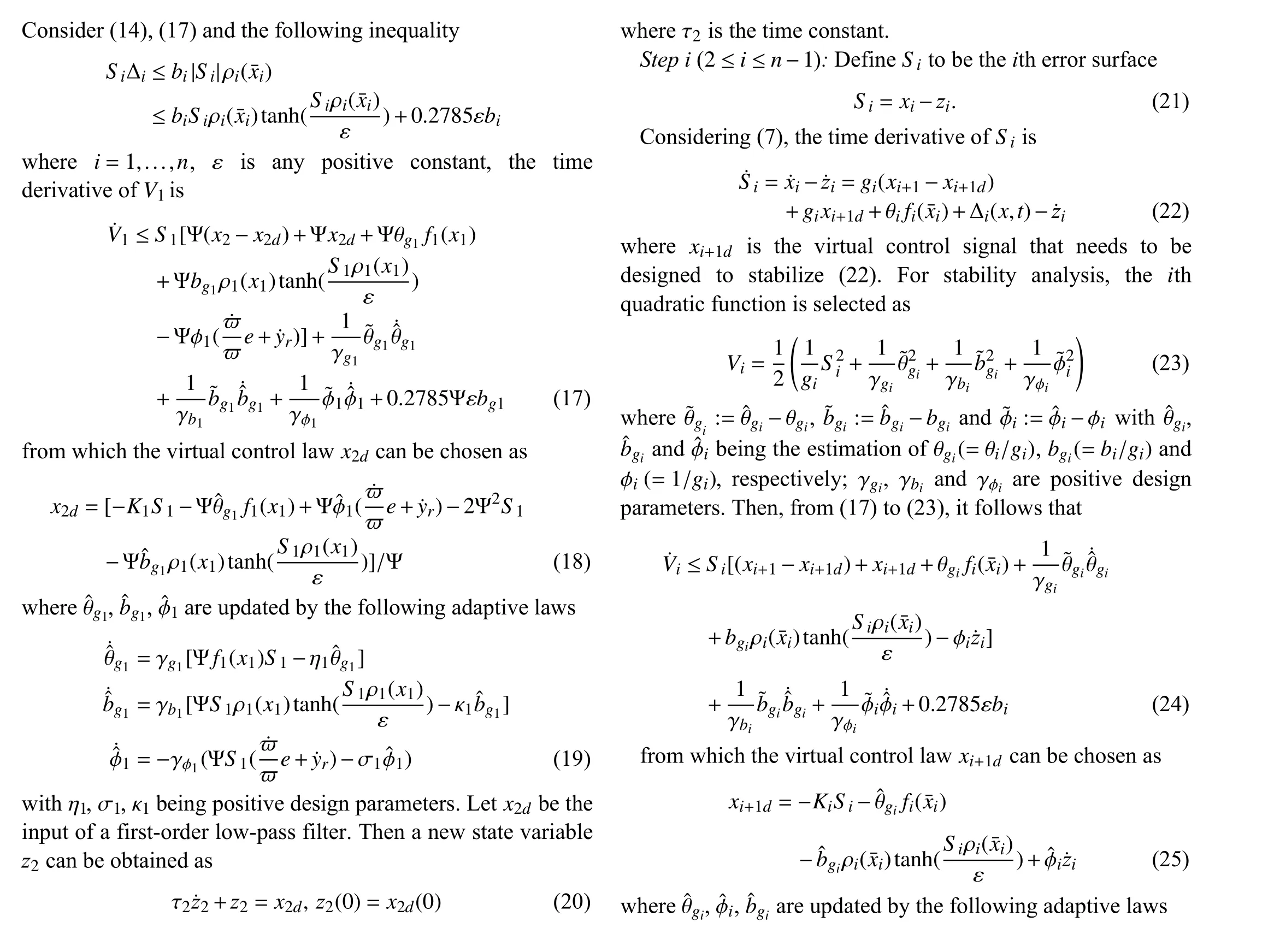
Step 1: From (10) and inspired by [38], the transformed error S1can be expressed as

from which the time derivative of S1can be obtained as

where x2dis a virtual control signal. Defined

Then, from properties of ϖ and Φ(·) in (9), (10) and (11),Ψ>0. For stability analysis, the first quadratic function is selected as


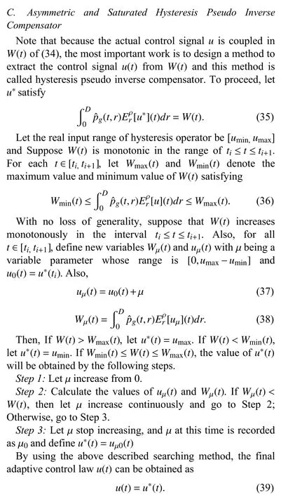
Remark 4: For the output-feedback control of hysteretic nonlinear systems, the key point is to design a states observer to estimate the unmeasurable states. However, it is difficult because the hysteresis output may have no boundary when the input has no boundary. In the proposed pseudo inverse control scheme, because the whole hysteresis part in (32) is regarded as a temporary control signal, an on-line calculation mechanism of approximately control signal is developed by applying a searching method in (35)–(39) to the designed temporary control signal where the true control signal is coupled. Therefore, the obstacle of constructing states observer as that in [29] and [30] is absolutely cleaned.
IV. STABILITY ANALYSIS
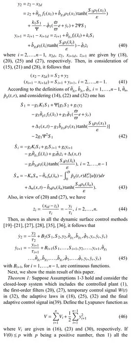
In this section, the analysis of stability will be carried out to show the effectiveness of the proposed control scheme.Moreover, the utilization of the first-order low-pass filters in the design process can simplify the design process. However,we have to pay that the process of the stability analysis will become complicated. Define the errors between the input and output of the first-order low-pass filters as

V. EXPERIMENTS ON HARDwARE-IN-LOOP PLATFORM
In this section, the hardware-in-loop testing platform is used to demonstrate the performance of the proposed control scheme. The experiment environment is shown in Fig.3,where the real-time simulator (RTS) is built by Simulink or StarSim software on FPGA chips. It can simulate the characteristics of the controlled object and send the response signals to the controller box in real-time. The rapid control prototype (RCP) is used to run the control algorithm download from StarSim RCP software in real-time and send control signals to RTS to complete the closed-loop experimental system. The adapter plate is used to realize the signal connection between the RCP and RTS. Host computer is used to realize the online parameters adjustment and real-time response signals observation. Also, the diagram of the hardware-in-loop platform is constructed as shown in Fig.4, where the hardware configuration includes the following parts.
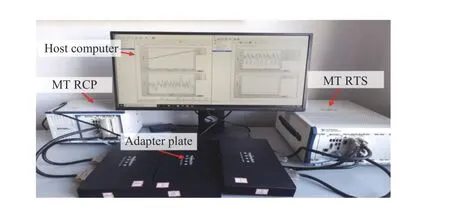
Fig.3. The whole experiment environment.
1) NI PXIe-1082 chassis: the chassis can meet the needs of various high-performance test and measurement applications,including Kintex-7 325T FPGA @Xilinx chip that can achieve 26-channel synchronous analog output and 14-channel synchronous analog input, where the real-time simulation step sizes up to 250 ns–1.5 μs.
2) NI PXIe-1071 chassis: the chassis includes a Kintex-7 325T FPGA @Xilinx chip that can implement 16-channel synchronous analog output and 16-channel synchronous analog input, where the real-time simulation step size can reach 250 ns–1.5 μs.
3) Adapter plate: it is used to realize the signal connection between the RCP and RTS.
4) Host computer: it is used to realize the online parameters adjustment and real-time response signals observation.
In the hardware-in-loop testing platform, the following second-order controlled plant with unknown saturated-type PI hysteresis as the input is considered [35], [36] and this mathematical model is download into the RTS via simulink model of MATLAB.
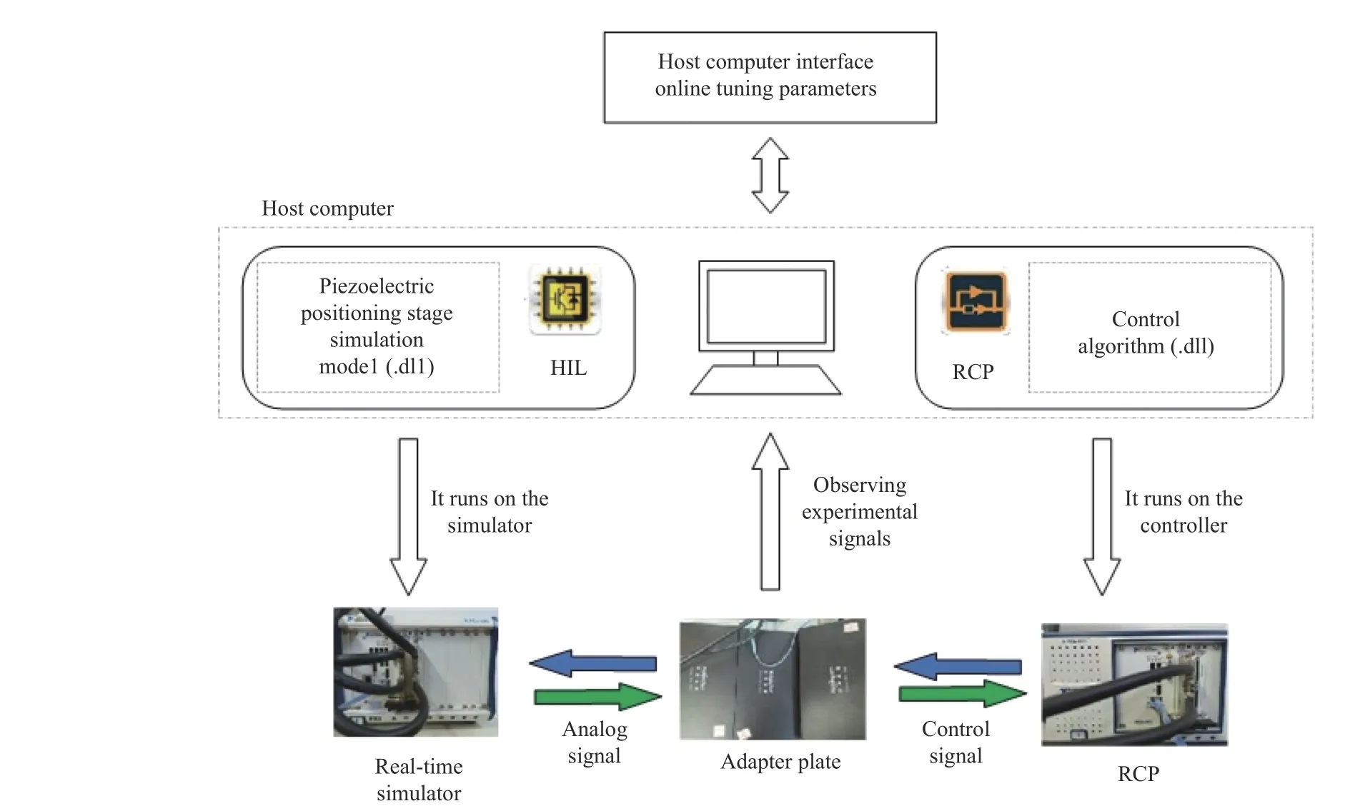
Fig.4. The experimental system architecture.

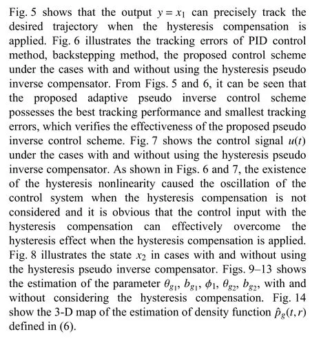
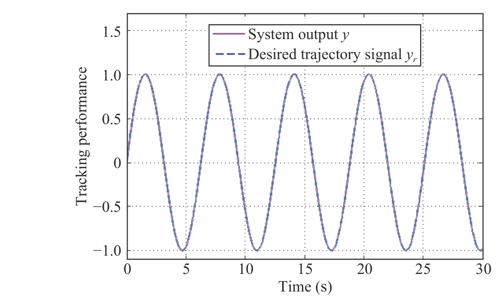
Fig.5. Case 1: y and yr with the method of pseudo inverse.

Fig.6. Case 1: Tracking errors with and without hysteresis compensation,backstepping control and PID control.


Fig.7. Case 1: Control signals with and without hysteresis compensation.
Fig.8. Case 1: State x2(t) with and without hysteresis compensation.
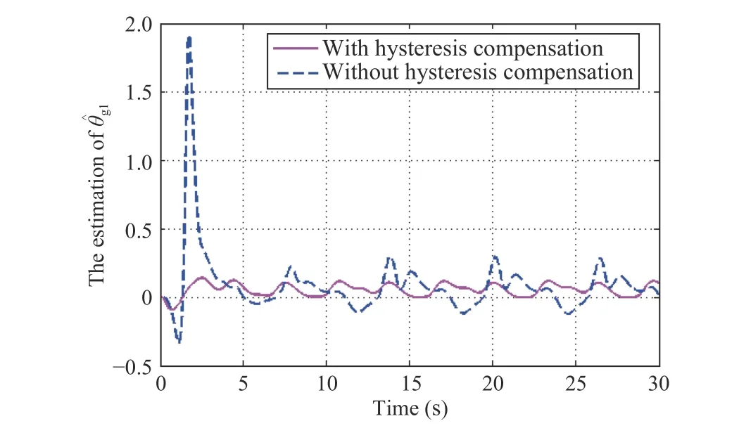
Fig.9. Case 1: Estimation of unknown parameter with and without hysteresis compensation.

Fig.10. Case 1: Estimation of unknown parameter with and without hysteresis compensation.
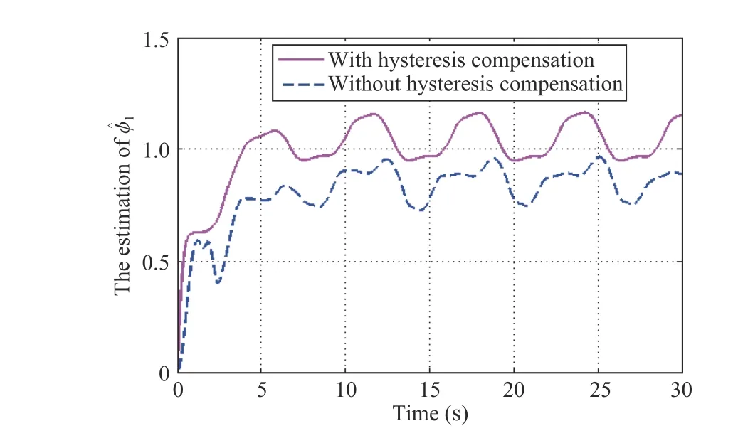
Fig.11. Case 1: Estimation of unknown parameter with and without hysteresis compensation.
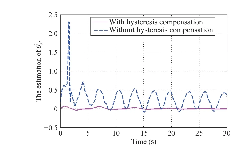
Fig.12. Case 1: Estimation of unknown parameter with and without hysteresis compensation.

Fig.13. Case 1: Estimation of unknown parameterwith and without hysteresis compensation.

Fig.14. Case 1: Estimation of unknown hysteresis density

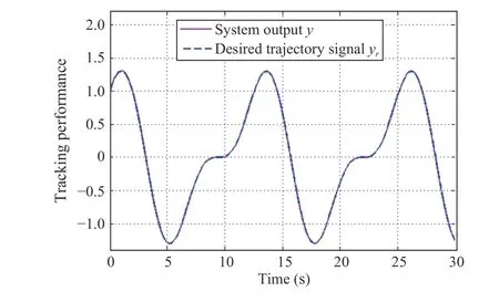
Fig.15. Case 2: y and yr with the method of pseudo inverse.
VI. CONCLUSION

Fig.16. Case 2: Tracking errors with and without hysteresis compensation,backstepping control and PID control.

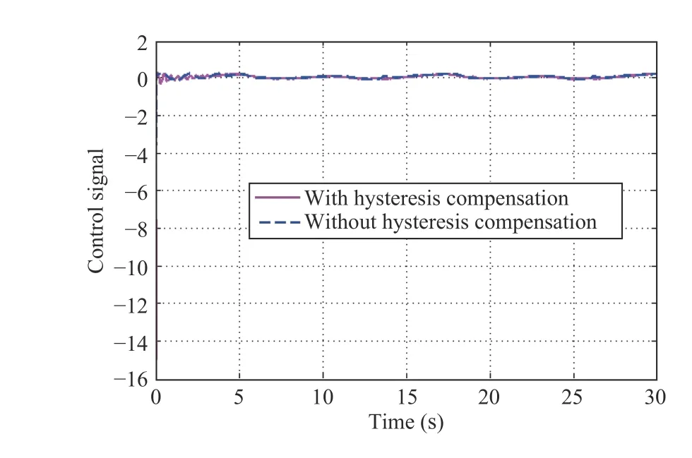
Fig.17. Case 2: Control signals with and without hysteresis compensation.
In this paper, a robust adaptive dynamic surface pseudo inverse control for a class of nonlinear asymmetric and saturated nonlinear hysteretic systems has been proposed.Firstly, an on-line calculation mechanism of approximate control signal is developed by applying a searching method to the designed temporary control signal. Secondly, the construction of true explicit hysteresis inverse and the identifications of its corresponding unknown parameters are not required when dealing with the saturated-type hysteresis.Thirdly, the tracking error transformed function is properly designed, then, the prespecified tracking performance is achieved. Finally, the experiments are implemented on the hardware-in-loop platform to verify the validity of the proposed adaptive pseudo inverse control scheme. To our best knowledge, the proposed pseudo inverse hysteresis control scheme provides a new idea for mitigating the creep property of hysteresis without constructing explicit or estimated inverse model. Future works will focus on the digital pseudo inverse control of nonlinear hysteretic systems with creep property and its application to the smart-material actuators based positioning systems, which is more suitable for computer control.
APPENDIX
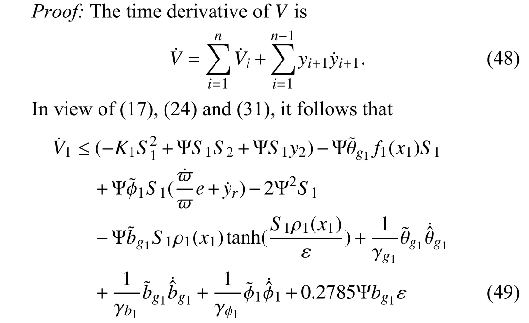
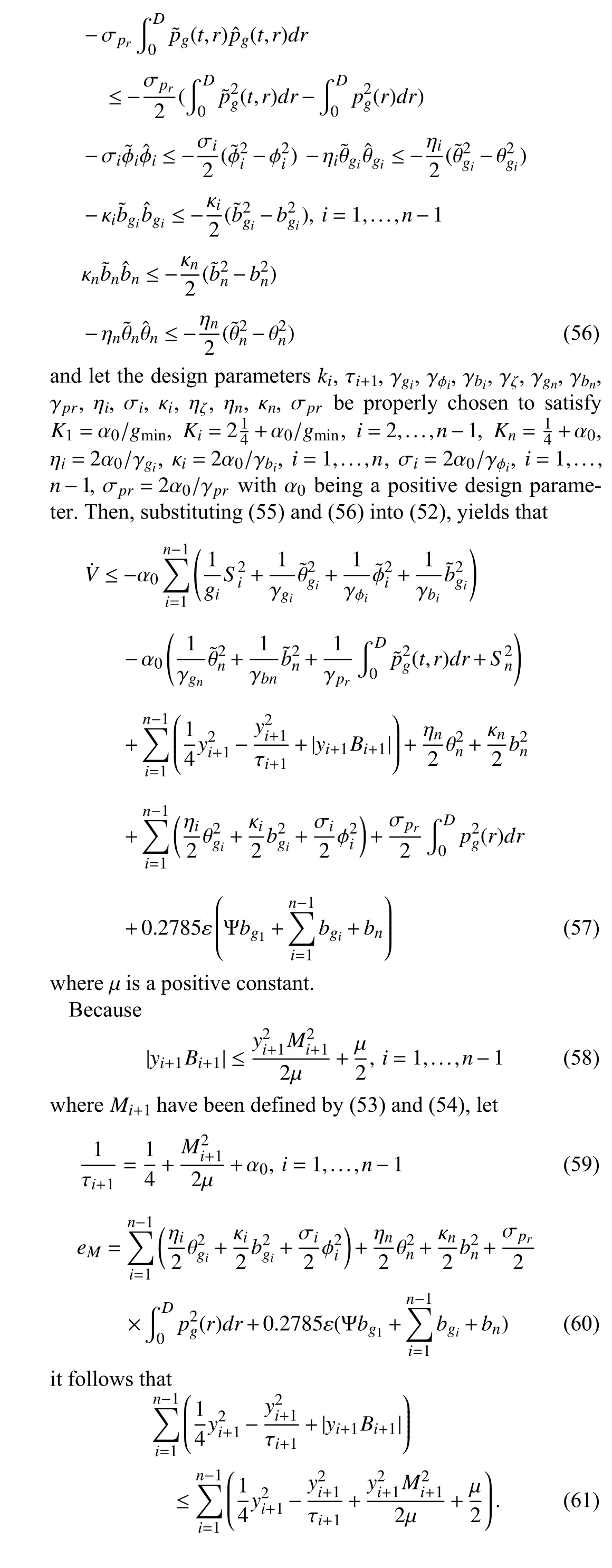
PROOF OF THEOREM I

杂志排行
IEEE/CAA Journal of Automatica Sinica的其它文章
- Residual-driven Fuzzy C-Means Clustering for Image Segmentation
- Decoupling Adaptive Sliding Mode Observer Design for Wind Turbines Subject to Simultaneous Faults in Sensors and Actuators
- Task Scheduling for Multi-Cloud Computing Subject to Security and Reliability Constraints
- Vibration Control of a High-Rise Building Structure: Theory and Experiment
- Fixed-Time Output Consensus Tracking for High-Order Multi-Agent Systems With Directed Network Topology and Packet Dropout
- Dynamic Evaluation Strategies for Multiple Aircrafts Formation Using Collision and Matching Probabilities
