New correlated MIMO radar covariance matrix design with low side lobe levels and much lower complexity
2021-03-16RoholahVAHDANIHosseinKHALEGHIBIZAKIMohsenFALLAHJOSHAGHANI
Roholah VAHDANI, Hossein KHALEGHI BIZAKI,Mohsen FALLAH JOSHAGHANI
Department of Electrical and Computer Engineering, Maleke Ashtar University of Technology, Tehran 1774-15875, Iran
KEYWORDS Beampattern;Correlated MIMO radar;Covariance matrix design;Sidelobe level;Signal-to-Interference Plus Noise Ratio (SINR)
Abstract In this paper,a new correlated covariance matrix for Multi-Input Multi-Output(MIMO)radar is proposed,which has lower SideLobe Levels(SLLs)compared to the new covariance matrix designs and the well-known multi-antenna radar designs including phased-array,MIMO radar and phased-MIMO radar schemes.It is shown that Binary Phased-Shift Keying(BPSK)waveforms that have constant envelope can be used in a closed-form to realize the proposed covariance matrix.Therefore,there is no need to deploy different types of radio amplifiers in the transmitter which will reduce the cost, considerably. The proposed design allows the same transmit power from each antenna in contrast to the phased-MIMO radar. Moreover, the proposed covariance matrix is full-rank and has the same capability as MIMO radar to identify more targets,simultaneously.Performance of the proposed transmit covariance matrix including receive beampattern and output Signal-to-Interference plus Noise Ratio (SINR) is simulated, which validates analytical results.
1. Introduction
In the past decade, multi-antenna radar systems especially Multi-Input Multi-Output (MIMO) radars and phased-MIMO radars have been made much attention to in researches of this field.1-12MIMO radar has two main types: One is the separated MIMO radar where the transmitting and the receiving antennas are located so far from each other(in comparison with the wavelength). This type enhances spatial diversity.9Another type is the co-located MIMO radar where the antennas are closely spaced.2This type has some good advantages like better interference rejection, improvement of parameter identifiability and enhancing flexibility in beampattern design.13-16Our focus in this paper is the co-located MIMO radar. Besides, the phased-MIMO radar idea that was proposed by Hassanien and Vorobyov3divides antenna array to some different sub-arrays. Waveforms in each sub-array are fully correlated same as phased-array radars,and two different sub-arrays have different stochastic properties like MIMO radars. Phased-MIMO scheme achieves better receive beampattern with lower SideLobe Levels(SLLs)in comparison with phased-array and MIMO radar.3
MIMO radar waveform design is recently focused on by researchers.6-8Transmit signals and receive filter are jointly designed in Ref. 6 to improve the SINR using a quasiconvex-based optimization algorithm. Moreover, the problem of the joint design of transmit waveform and receive filter for MIMO radar with a Peak-to-Average Power Ratio (PAPR)constraint and a similarity constraint had been addressed in Ref.7.Also,the MIMO radar waveform design problem with keeping some features in transmit beampattern is discussed in Ref. 8. One of the main disadvantages in all of these approaches is that constant modulus waveform is not guaranteed.
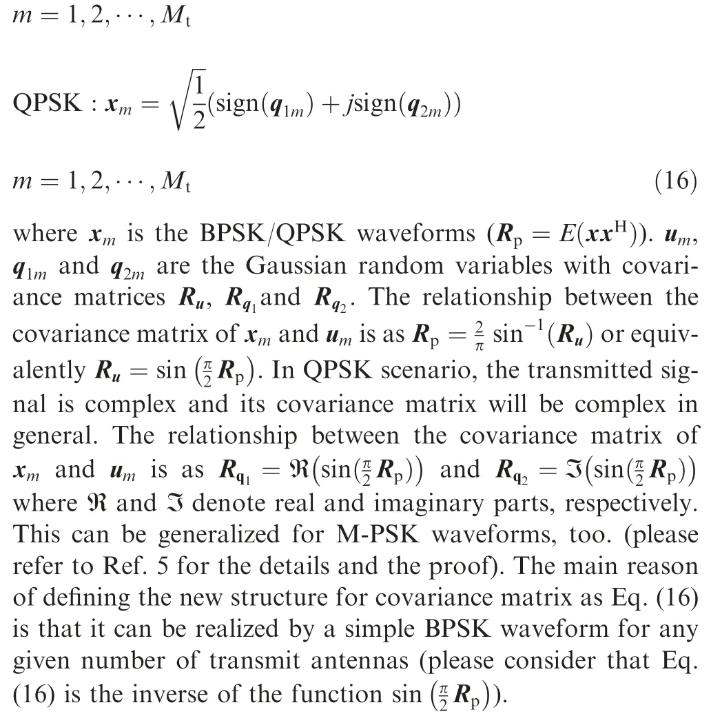
In Ref. 5, new algorithms were proposed to generate finite alphabet constant envelope waveforms with required crosscorrelation properties. In radar and all communication systems, it is a practical key feature that the transmit waveforms have constant envelope to allow radio frequency amplifiers to operate at maximum power efficiency.5Thus, with the constant envelope scheme in Ref. 5, only one type of amplifier is needed which will also reduce the cost,considerably.Constant envelope scheme in MIMO radars uses the mapping function between Gaussian random variables to a constant Binary/Quadratic Phase Shift Keying (BPSK/QPSK) to realize the desired covariance matrix. This mapping function requires some initial conditions that can be met by only some of the covariance matrices.4,5Fortunately, the proposed covariance matrix in this paper can be realized by a constant BPSK/QPSK waveform.
Parameter identifiability of the MIMO radar was discussed in Ref. 10. This parameter is a consistency aspect that is used to establish the uniqueness of the parameter estimation problem as SINR or the number of snapshots goes to infinity.10As derived in Ref. 11, the parameter identifiability of multiantenna radar systems depends on the rank of the transmit covariance matrix and the geometry of the transmit and receive arrays. In MIMO radar, all transmit waveforms are uncorrelated and thus covariance matrix of the MIMO radar is full rank and has the ability to identify the maximum number of targets in comparison with phased-array radar whose covariance matrix is rank one. The rank of the covariance matrix in the phased-MIMO radar is less than that in the MIMO radar scenario,and thus its identifiability performance is worse than that of MIMO radar and better than that of phased-array design.
In this paper, we discuss the transmit covariance matrix of different co-located multi-antenna radar schemes and their receive beampattern and SINR performance. Then we will propose a new design for the transmit covariance matrix with better receive beampattern compared with traditional ones.We will show that our proposed scheme also has better practical features. It will be shown that the proposed covariance matrix is full-rank, so it can identify the maximum number of targets same as MIMO radars while it can achieve lower SLLs in the receive beampattern, too. In our study of correlated MIMO radar covariance matrix design, we make some main contributions which are summarized as follows: (A) A new covariance matrix design is proposed, which has the lowest SLLs in the receive beampattern in comparison with the traditional schemes in Refs. 2-5,12. (B) The proposed covariance matrix can be realized by a simple BPSK waveform in contrast to the covariance matrix with cosine structure5which has the same receive beampattern performance. Thus the proposed covariance matrix is more preferred. (C) The proposed scheme has low hardware/software complexity because there is no need to deploy different types of radio amplifiers in the transmitter. This will reduce the cost, considerably due to the fact that the proposed design allows the same transmit power from each antenna in contrast to phased-MIMO radar. (D)The most recent design in Ref. 5 has the lowest SLL among traditional schemes. While the rank of the mentioned covariance matrix in Ref.5 always equals two regardless of any number of transmit antennas, our proposed covariance matrix is always full-rank, and thus it has the same capability as the MIMO radar to distinguish multiple targets, simultaneously.
The remainder of the paper is organized as follows. In Section 2,the model of co-located MIMO radar with multiple antenna elements and multi-target scenario are described. In Section 3, an overview of different covariance matrix designs and their SINR and beampattern performances are presented.The proposed covariance matrix design and its performance are described in Section 4. Simulation results and concluding remarks are presented in Section 5 and Section 6,respectively.
2. System model
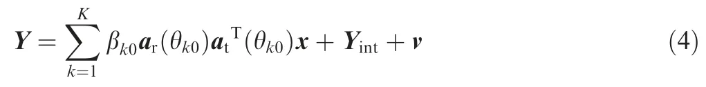
Consider the MIMO radar withMtandMrtransmit and receive antennas, respectively. Antennas are co-located with half-wavelength spacing in both the transmitter and receiver sides.Also,suppose that there areLnumber of interferers that are affecting the received signal strength. Thus, the receivedMr×1 baseband signal vector at the receiver can be expressed as4

where x is theMt×1 vector of transmitted symbols. θ0is the location of the target and thei-th interference is located at θi.Also β0and βiare the Radar Cross-Sections(RCSs)of the target andi-th interference,respectively.v represents the vector of additive white Gaussian noise term with zero mean andvariance. Besides, at(θ) and ar(θ) areMt×1 transmit andMr×1 receive steering vectors, respectively, which can be expressed as1

At each receive antenna,the received signal passes through a matched-filter and the output samples are correlated withMttransmit symbols in a specific timeslot.Therefore,we will haveMtsamples in eachMrreceive antennas which can be cascaded in a vector form of sizeMtMr×1 as4

where R is t he transmit covariance matrix as R=E(x xH)(E(·)and (·)Hdenotes expectation operator and conjugate transposition of (·), respectively), vcis theMrMt×1 vector of circularly symmetric white Gaussian noise samples each with zero mean andvariance, and ⊗denotes the Kronecker product.The desired signal is represented by yc,0and the interference term is denoted by yc,int. According to Eq. (3), the transmit covariance matrix is the key factor in the output performance of the MIMO radar,including SINR,receive beampattern,etc.
In the next subsection, the system model will be presented for multi-target scenarios.
One of the most important issues in radar is the parameter identifiability, which is the maximum number of targets that can be uniquely identified at the same time.10,11In the multitarget scenario, the baseband signal at the receiver can be expressed as8
whereKis the number of targets and thek-th target is located at θk0.Also βk0is the RCS related to thek-th target.Yintis the matrix of interference term. Then, the identifiability equation can be written as11

In the next section, a brief overview of different correlated MIMO covariance matrix designs and their advantages/disadvantages are presented.
3.Traditional covariance matrix designs and their performances
As can be interpreted from Eq.(3),the received signal consists of desired signal and interference plus noise terms.Considering the received samples in Eq.(3),SINR of a specific target can be achieved. The beamforming vector w of sizeMtMrcan be designed in the output of the matched-filter to maximize the SINR. By multiplying the received signal vector with the beamformer, we can write

Using Eq. (6), the output SINR for a single target can be defined as4

where sm(θ)≜ar(θ)⊗Rat(θ) and Rinis theMtMr×MtMrcovariance matrix of interference plus noise samples and can be expressed as

The best value of the beamformer vector w to maximize SINR can be achieved by the Minimum Variance Distortionless Response (MVDR) method.1Also, the low complex conventional beamformer could be achieved as10

The optimum SINR will be achieved when the interference term is zero.In this case,by using conventional beamformer in the receiver, the optimum SINR can be expressed as4

The output SINR value in Eq.(10)depends on the value of the covariance matrix.Therefore, we will have different SINR performance by choosing different covariance matrices.
In addition, in correlated MIMO radar (or generally in multi-antenna radar systems), the transmit beampattern can be expressed as11

that is a function of the transmit covariance matrix. Also, the received power from the direction of θ can be given by11

Thus, it can be deduced from Eq. (12) that different transmit covariance matrices lead to the receive beampatterns with different properties such as different SLLs and null points.
In Table 1, different traditional transmit covariance matrices (including MIMO radar,2phased-array,4phased-MIMO3,R1x,12, R2x,5and R3x16) and their performances are summarized. As it is mentioned in this table, phased-array radar has the best SINR performance while R2xhas a better receive pattern with a higher number of null points as depicted in Fig. 1, receive beampattern is simulated forMt=Mr=10.
Although R2xhas some advantages like lower sidelobe level and high capability for interference rejection, it has some disadvantages. sinis not always positive semi-definite,and thus BPSK waveforms cannot always be found in closed-form to realize it.5Besides, the rank of R2xis always two which shows that increasing number of transmit antennas will not enhance its capability to identify more targets at the same time. This is one of the main disadvantages of R2x.5
Consider SINR of R2xin Table 1. When the number of transmit antennas increases to very large values, the optimum SINR in this case can be approximated by using Taylor expansion of 1-cos

In the next section, our proposed correlated MIMO radar scheme will be presented. Also, its performance will be compared with traditional schemes. It will be shown that the new proposed covariance matrix design outperforms other designs from different points of view, especially receive beampattern and SLLs while it can be realized by simple BPSK waveforms unlike R2x.
4. Proposed covariance matrix design
In this section,we propose a transmit covariance matrix structure with receive beampattern performance similar to R2x.Besides,the proposed covariance matrix has much better practical properties in comparison with other traditional mentioned designs like phased-array, MIMO radar, phased-MIMO and R1x. The proposed covariance matrix is represented as

where A is defined as

BPSK:xm=sign(um)
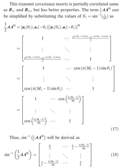
Therefore, the proposed covariance matrix in Eq. (14) can be expressed equivalently as

Generally, the (i,j)-th element of Rpis given by 1-2|i-j|/Mt. Every proposed covariance matrix design should be positive semi-definite and symmetric17, and thus a transformation of the transmitted signal to realize the mentioned covariance matrix could always be found. These are the necessary and sufficient conditions that any covariance matrix should have.Besides,if the proposed covariance matrix is full-rank, it can determine the maximum number of targets,same as MIMO radar.11Here,two propositions about the proposed covariance matrices are presented and proved.
Proposition 1.The proposed transmit covariance matrixRpis always positive definite.
Proof.The proposed covariance matrix in Eq. (16) can be expanded by Taylor series as:


Proof:.According to Proposition 1, Rpis always positive definite and all positive definite matrices have nnon-zero positive eigenvalues.Therefore,Rphas Mtpositive eigenvalues and the proof is completed.
This is one of the key features of the proposed covariance matrix because it uses full diversity and has capability to reject more interferences compared with phased-array, phased-MIMO and R2x.
4.1. Receive beampattern
By using conventional beamformer in the receiver, according to Eq. (12),the receive beampattern of Rpcan be expressed as

In addition to having good practical features such as the existence of BPSK waveform in a closed-form to realize Rp,the receive beampattern of the proposed design has the same trend compared to R2x, which is the best performance among prior mentioned designs.Also,the proposed covariance matrix leads to many null points same as R2xwhich shows its high interference rejection capability.
4.2. Optimal SINR of proposed scheme
By using conventional beamformer in the receiver and the result of linear algebra, Eq. (10) can be simplified as11

The covariance matrix Rpdepends only on the number of transmit antennas,Mt. Therefore, SINR can be expressed as a function ofMt. To demonstrate this dependence, assume that the angle of the target is θ0=0, then we have

Thus, according to Eqs. (23) and (25), the optimum SINR in the proposed method when there is no interference term can be expressed as
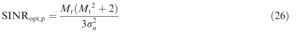
which shows that the SINR of the proposed covariance matrix is better than the MIMO radar and R1x, but worse than R2x.ForMt=1, SINRopt,p=SINRopt,phand therefore there is no loss in the output optimum SINR value. When the number of transmit antennas increases to very large values, the optimum SINR in Eq. (26) can be approximated as
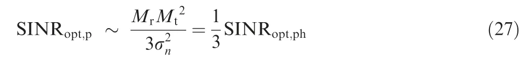
which shows 10 lg(1/3)=-10.98dB SINR loss in comparison with optimum SINR of phased-array for large values ofMt.For the lower number of transmit antennas, the SINR performance of the proposed design is much closer to the covariance matrix R2x. This is the only disadvantage of the proposed scheme in comparison with R2x. According to Eq.(27), whenMtincreases, SINR of the proposed design is one-third of the SINR in phased-array which has the best SINR performance among mentioned structures.
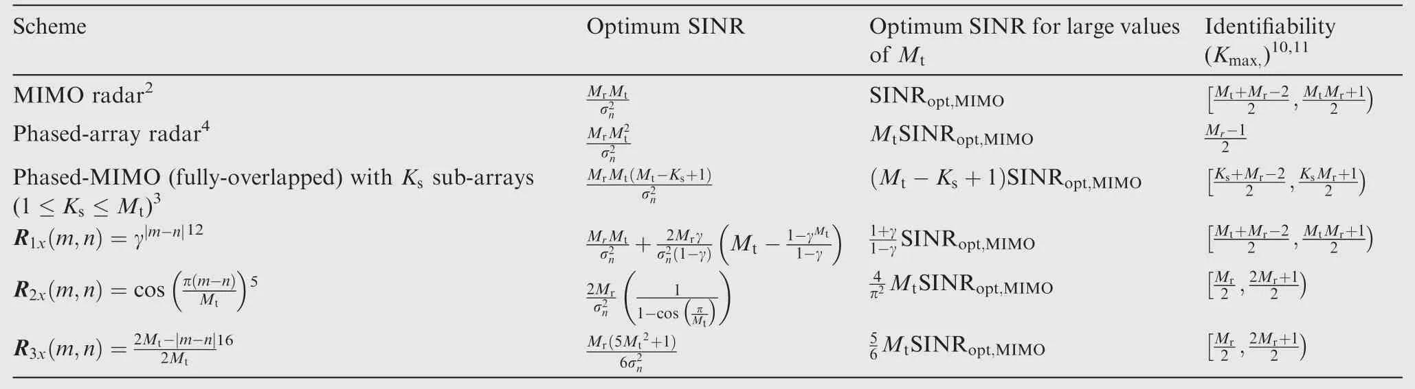
Table 1 Comparison of SINR and identifiability parameter in different multi-antenna radar schemes.

Fig. 1 Normalized receive beampattern obtained using conventional beamformer of MIMO radar,phased-array,phased-MIMO(Ks =6), R1x (γ=0.5), R2x and R3x.
4.3. Parameter identifiability
In this part,we want to determine the parameter identifiability of the proposed scheme in a multi-target scenario. As derived before,the proposed covariance matrix is full rank and it is the same as MIMO radar in parameter identifiability point of view.
When the transmit and receive arrays share maximum antennas, the identifiability Eq. (5) or equivalently ar(θk0)⊗Rpat(θk0) has onlyMt+Mr-1 distinct values. On the other hand, when the transmit and receive arrays share no antenna,ar(θk0)⊗Rpat(θk0)will have maximumMrMtdistinct values. Thus, the dimension of distinct equations will be in the following range


which shows that the proposed design has the same capability as MIMO radar from parameter identifiability point of view.
4.4. Design criteria
Suppose that the covariance matrix of the form is

where α is the design parameter. The proposed design and R3are different in the value of α. It is obvious that for α=1,R=R3and for α=4, R=Rpwill be achieved. Let’s investigate the bounds of α. Any content of R should be between-1 and 1 (this is the characteristic of any covariance matrix).Thus we have

So the bounds of α depend on the value ofMt. For large value ofMt, upper bound of α will tend to 4 asymptotically(0 ≤α ≤4). Simulation results in the next section will show that for α →4, better beampattern will be achieved (which is equal to the proposed design). Also when α →0, SINR value will tend to the SINR of the phased-array radar because the covariance matrix almost equals the matrix of all ones (like phased-array) and the optimum SINR will be achieved, while receive beampattern will have higher SLLs. Therefore, the design parameter (α) will determine the performance of the covariance matrices.
Here,let’s review the advantages and drawbacks of the proposed covariance matrix design which are summarized as follows
(2) Rank of Rpalways equals Mtwhich shows that the proposed design has the same capability as MIMO radar in identifying unique targets,also by increasing the number of transmit antennas, and the parameter identifiability of the proposed design will be improved.
(3) Simulation results in the next session shows that the proposed design has SLLs almost equal to R2x,and thus has the best beampattern performance in comparison with other mentioned designs.
(4) It has the highest number of null points in the SLL area same as R2xwhich shows its high interference rejection capability.It has much more null points in side lobe area in comparison with phased-array,MIMO radar,phased-MIMO radar, R1x, R2xand R3x.
(5) The proposed scheme has loss in SINR instead of the above advantages.
In the next section, numerical results will be presented.
5. Simulation results
In this section, simulation results are presented for different mentioned covariance matrix designs. For R1x, the value of γ is chosen as γ=0.5. The following simulations are done for different values of the transmit and the receive antennas. In all SINR simulations, the interference to noise ratio assumed to be INR=30dB. In the first example, suppose that there areMt=12 andMr=12 antennas in the transmitter and in the receiver with half-wavelength inter-element spacing,respectively. Also, phased-MIMO radar withKs=6 fully overlapped sub-arrays is assumed. The normalized receive beampatterns of phased-array, MIMO radar, phased-MIMO radar, and correlated MIMO with R1xand R2xand the proposed transmit covariance matrix design are presented in Fig. 2, receive beampattern is simulated forMt=Mr=12.
As it can be seen in this figure, the proposed covariance matrix design has much lower SLLs compared to the phased-array,MIMO radar,phased-MIMO radar and the correlated MIMO radar with covariance matrix R1x. Besides, the SLLs of the proposed scheme are almost equal to the correlated MIMO radar with covariance matrix R2x. In Fig. 3, the SINR performance of the mentioned designs in this example is simulated for the case that there are two interferes, which are located at θ1=10° and θ2=-30°, receive beampattern is simulated forMt=Mr=12. As Fig. 3 shows, the SINR of the proposed design is only 0.9dB lower than the SINR of R2x. When there is no interference, this gap will be deducted to 0.81dB.This is the cost that should be paid to have the best receive beampatterns compared to the prior mentioned designs.
Above simulations are repeated for R1x, R2x, R3x, phasedarray and MIMO radar withMt=20,Mr=10, and phased-MIMO radar scheme (withKs=10 number of fully overlapped sub-arrays). It can be seen in Fig. 4 that the proposed covariance matrix design outperforms other mentioned schemes as same as the previous example and also has better practical features as discussed in Section 4. The proposed scheme can distinguish more targets because of having lower SLLs in the receive beampattern.

Fig. 2 Normalized receive beampattern obtained using conventional beamformer of phased-array,MIMO radar,phased-MIMO(Ks =6), R1x (γ=0.5) and R2x.

Fig. 3 Comparison of SINR using the proposed design with MIMO radar, phased-array, phased-MIMO (Ks =6), R1x(γ=0.5) and R2x.
Fig. 5 compares the SINR performance of the proposed scheme with prior mentioned designs, receive beampattern is simulated forMt=20,Mr=10. In this example, the difference between the SINR of Rpand R2xis only about 0.4 dB.It shows that the interesting results of the proposed design will be achieved with the cost of losing a fraction of SINR which is compared in Fig. 5.
Based on the design criteria in previous section, receive beampattern is simulated forMt=20,Mr=10 and different values of α in Fig. 6. It is shown that the proposed design will have the lowest SLLs among other designs.
In Fig. 7, the beampatterns of the proposed scheme using 500 and 10,000 generated BPSK waveforms are compared with the beampattern of Rp(which will be realized by infinite number of waveforms), receive beampattern is simulated forMt=20,Mr=10.When the number of waveform realizations increases, the performance of the generated waveforms will reach to the performance of Rp, asymptotically. It shows the success of the closed-form BPSK waveform generation in Eq. (18) as it was expected.
Table 2 shows optimum SINR for different numbers of transmit and receive antennas when there is no interference term. Based on the SINR of different designs which were derived in the previous sections, by increasing number of antennas, the output SINR will be increased. As discussed before,although the proposed scheme has a lower SINR value compared with R2x, it has much better practical features as mentioned before.

Fig. 4 Normalized receive beampattern obtained using conventional beamformer of phased-array, MIMO radar, R1x (γ=0.5),R2x and R3x.

Fig. 5 Comparison of SINR using the proposed design with MIMO radar, phased-array, R1x (γ=0.5), R2x and R3x.

Fig. 6 Normalized receive beampattern for Mt =20,Mr =10 and different values of α.

Fig. 7 Comparison of receive beampattern using proposed design, BPSK waveform in 500 and 10,000 iterations. Also Mt =20,Mr =10.
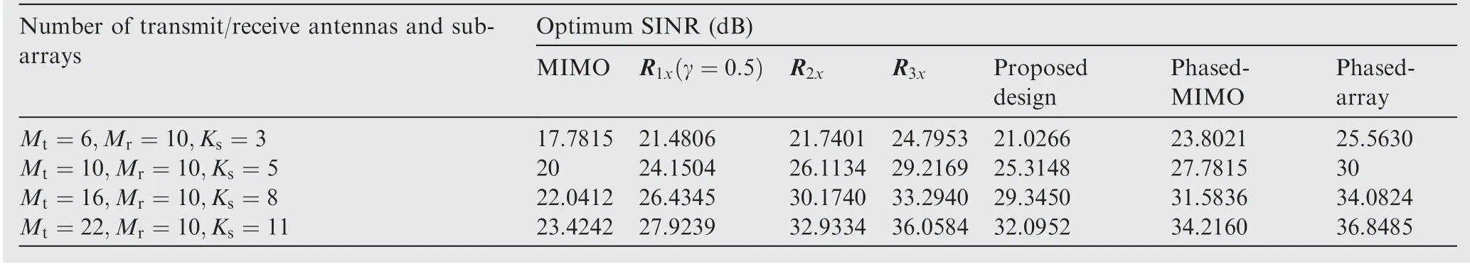
Table 2 Optimum SINR values (dB) in different schemes when there is no interference.
6. Conclusions
In this work, a new covariance matrix design is proposed to exploit the advantages of both MIMO radar and phasedarray. The conclusion is summarized as follows:
(1) The proposed scheme achieves lower SLLs and much more null points in receive beampattern compared with prior mentioned designs.
(2) BPSK waveforms which are constant envelope can be used in a closed-form to realize the proposed covariance matrix. Thus, there is no need to deploy multiple radio amplifiers in the transmitter which will reduce the cost,considerably.
(3) The proposed covariance matrix enables the maximum number of targets that can be unambiguously identified by the radar to be up to Mttimes that of its phased-array counterpart. In other words, it is shown that the proposed design can determine the maximum number of targets like MIMO radars.
(4) Instead of achieving these benefits,the proposed scheme has a little SINR loss.As shown in Section 4,when there is no interference, SINR loss will not exceed 10.98dB.This depends on the geometry of the array and the number of transmit and receive antennas.
Declaration of Competing Interest
The authors declare that they have no known competing financial interests or personal relationships that could have appeared to influence the work reported in this paper.
杂志排行

CHINESE JOURNAL OF AERONAUTICS的其它文章
- Tangling and instability effect analysis of initial in-plane/out-of-plane angles on electrodynamic tether deployment under gravity gradient
- Aerodynamic periodicity of transient aerodynamic forces of flexible plunging airfoils
- Effects of swirl brake axial arrangement on the leakage performance and rotor stability of labyrinth seals
- Experimental and computational investigation of hybrid formation flight for aerodynamic gain at transonic speed
- Tomography-like flow visualization of a hypersonic inward-turning inlet
- Hypersonic reentry trajectory planning by using hybrid fractional-order particle swarm optimization and gravitational search algorithm