Hypersonic reentry trajectory planning by using hybrid fractional-order particle swarm optimization and gravitational search algorithm
2021-03-16KhurramSHAHZADSANAWeiduoHU
Khurram SHAHZAD SANA, Weiduo HU
School of Astronautics, Beihang University, Beijing 102206, China
KEYWORDS Fractional-order;Gravitational search algorithm;Particle swarm optimization;Reentry gliding vehicle;Trajectory optimization
Abstract This paper proposes a novel hybrid algorithm called Fractional-order Particle Swarm optimization Gravitational Search Algorithm(FPSOGSA)and applies it to the trajectory planning of the hypersonic lifting reentry flight vehicles.The proposed method is used to calculate the control profiles to achieve the two objectives, namely a smoother trajectory and enforcement of the path constraints with terminal accuracy. The smoothness of the trajectory is achieved by scheduling the bank angle with the aid of a modified scheme known as a Quasi-Equilibrium Glide (QEG)scheme. The aerodynamic load factor and the dynamic pressure path constraints are enforced by further planning of the bank angle with the help of a constraint enforcement scheme.The maximum heating rate path constraint is enforced through the angle of attack parameterization.The Common Aero Vehicle (CAV) flight vehicle is used for the simulation purpose to test and compare the proposed method with that of the standard Particle Swarm Optimization (PSO) method and the standard Gravitational Search Algorithm (GSA). The simulation results confirm the efficiency of the proposed FPSOGSA method over the standard PSO and the GSA methods by showing its better convergence and computation efficiency.
1. Introduction
Trajectory planning of the hypersonic gliding vehicle is to compute the control profiles and thus to compute a flyable and smoother trajectory from the initial point to the terminal point with the prescribed accuracy. The aerodynamics is responsible for providing support to these vehicles against gravity. The hypersonic gliding vehicles with a higher Lift to Drag (L/D) ratio, for example, Hypersonic Technology Vehicle-2 (HTV-2)1and Common Aero Vehicle (CAV),2have the capabilities of enhancement of their downrange/crossrange, efficiency, and precise target detection. Due to these capabilities, the trajectory planning of these vehicles becomes a vital area of research. These flight vehicles are commonly controlled by the scheduling of bank angle and angle of attack.
Direct and indirect techniques are two types of numerical methods that are used for the trajectory planning of these vehicles. Indirect techniques are centered around the Pontryagin minimum principle,3whereas the direct technique control profile is discretized at pre-defined points and solves it by nonlinear programming.The pseudospectral method and its variants are sub-types of direct techniques.These methods are based on the Gauss, Legendre, or Chebyshev polynomials.4,5These techniques are limited because of their dependence on the initial condition/ collocation point and basis function.
The primary work on reentry trajectory planning is the design of the shuttle entry guidance.6Acceleration due to atmosphere drag acceleration is scheduled to integrate the anticipated region (60 nautical miles before the landing site and Mach number of 2.5) by fulfilling the vehicle constraints and track the angle of attack. The mentioned technique is restricted to the prior flight missions, and many researchers made the efforts to recommend robust trajectory planning method.7,8
In this research, the trajectory is planned by assuming the constraints based on the no-fly zone and satisfying the waypoint.9Parameterization of the reference profile, along with the bank reversal logic, is studied and an analytical solution is proposed for the three-dimensional entry trajectories with a fixedL/Dratio.10These analytical solutions had limited use due to the assumption made during the derivation. A predictor-corrector method is applied for the trajectory generation and the LQR method for trajectory tracking in this research.11Trajectory optimization based on the reliability of the Mars entry mission is proposed in this study.12The maximum range trajectory for the Terminal Area Energy Management (TAEM) phase using the QEG at constant dynamic pressure is studied.13Time coordination entry guidance by considering the predictor-corrector guidance technique in the longitudinal phase and predictive guidance technique in the lateral plane is studied.14A control method based on the bank to turn is used for the online guidance method for the higherL/Dreentry flight vehicle.15
Swarm based optimization techniques are becoming famous during recent years to enhance convergence performance. The Genetic Algorithm (GA) is proposed for an optimal solution for spacecraft entry trajectory16and the spaceplane’s flight during the reconnaissance missions.17The Pigeon Inspired Optimization (PIO) method is employed for handling the terminal, and path constraints.18Model predictive control, along with the PIO, is applied to obtain the optimized trajectory of the gliding reentry vehicle.19PSO method is utilized to generate the optimal trajectory of the reentry spacecraft without calculating the derivative and Hamiltonian function.20The hybridization of the PSO with the Gauss pseudospectral method is used to plan the reentry trajectory generation of Mars landing.21PSO method is used in a various range of application problems. It requires a less number of parameters,and thus becomes attractive in the implementation point of view. It has a quicker convergence speed in comparison to the other evolutionary algorithms,like a Genetic Algorithm (GA). There are some shortcomings of the method due to its heuristic nature. It has unproductive global and weak local searching capability in the earlier and later iterations,respectively, which makes this algorithm computationally expansive and have lower accuracy. Some improvements to overcome the limitations in the standard version of the algorithm are proposed. A PSO variant based on the gradient of the function is introduced,which used the PSO during the global search,utilized the objective function derivative during the local search, and proved effective for the differentiable test functions.22This method is applicable for those objective functions which are differentiable. The stochastic gradient and the PSO methods are hybridized to plan the lifting reentry vehicle trajectory.23
In recent time metaheuristic algorithms based on the fractional-order calculus to model, the inertia coefficient is becoming common. Filter discretization by using the fractional-order Darwinian Particle Swarm Optimization Algorithm (FPSO) is studied.24H infinity controller design is proposed by using the Lagrangian FPSO in the recent study.25FPSO method is proved to have a better convergence property as compared to the standard version of the PSO at the cost of complexity in the memory. The Gravitational Search Algorithm (GSA) is based on the Newton law of gravity.26This algorithm has no memory complexity;however, it has a problem of premature convergence.
By using the capabilities of both FPSO and GSA,a hybrid method known as Fractional-Order Particle Swarm Gravitational Search Algorithm(FPSOGSA)is formalized.The FPSO method is used to enhance the accuracy,and the GSA method is used for the earlier convergence of the problem. The proposed FPSOGSA method is applied to plan the hypersonic reentry trajectory. In trajectory planning, the proposed method is used to compute the control profiles for the reentry gliding flight vehicle.The control profiles are calculated subject to achieve the smoothness in the trajectory and enforcement of the path constraints. Thus the outcome of the research is to ensure the flight vehicle safety.
The contribution of the research is briefed as below:
(1) Formulate a novel method known as FPSOGSA for trajectory planning of gliding reentry vehicles. The algorithm combines the accuracy of the FPSO and earlier convergence of the GSA method.
(2) Propose a modified QEG scheme by including the gravitational term for the elimination of the oscillations in state and the path constraints.
(3) Propose an alternative strategy to fulfill the path constraints, namely aerodynamic load factor and dynamic pressure,by the scheduling of the bank angle in contrast to the penalty factor method. Also, it enforces the heating rate path constraint through the parameterization of the angle of attack.
The proposed method falls in the class of predictor-corrector strategy,which requires the initial guess,and the use of the heuristic algorithm eliminates the use of the initial guess.
The paper organizes as follows. The trajectory dynamics model and its normalization are explained in Section 3. Section 4 describes the entry trajectory planning and formulation of the control variables. Section 5 describes the proposed FPSOGSA optimization algorithm,constraint handling procedure, and path constraint enforcement methods. In Section 6,a performance analysis based on the nominal and off-nominal conditions is discussed. A final section concludes the analysis presented.
2. Reentry trajectory modeling
In this section, we will formulate, model mathematically, and explain the procedure to compute the control variables profile and thus to achieve a feasible trajectory with the anticipated objectives.
2.1. Equation of motion
By using the assumption of a spherical rotating Earth model,the seven states model is considered. The states are known as(r,θ,φ,V,γ,ψ,sgo) radial position, longitude, latitude, speed,flight path angle, heading angle,27and range to go. The flight path angle is the angle between the velocity vector and horizontal plane,and the heading angle is measured positive clockwise from the North.The control variables include the angle of attack, α, and bank angle,σ. Usingmas the mass of the flight vehicle, the lift force isthe drag force isthe surface area isS, and the atmosphere density27is ρ=ρ0exp (-βh), with the value of constants ρ0=1.225 kg/m3and β=1.40845×10⁻⁴/m. The inverse square law for gravitygis adopted, where μ is the gravitational constant for the Earth with value of 3.96272×10¹⁴m3/s2, andReis the radius of the Earth with average value of 6378140 m.
The three-dimensional equation of motion for the lifting reentry flight vehicle is given as

2.2. Change of independent variable
A parameter known as a negative of the specific mechanical energy is defined and used as an independent variable. Variableewith its derivative is given as

By taking the specific mechanical energy as an independent variable, the terminal constraints on position and speed are converted into a single constraint on specific mechanical energy. The transformation of the state variablesfrom time to specific mechanical energy as an independent variable is given byThe transformed equation of motion is integrated between the initial and the final states. The initial conditions are based on the state parameters at the reentry point,and the final conditions are their values at the TAEM interface.
3. Reentry trajectory planning/optimization
Entry trajectory optimization is to compute the control variables profile subjected to state,path,and terminal constraints.The control variables profile includes the angle of attack and the bank angle.By optimizing specific design parameters,these control variables are computed. The models of the control variables are described as follows.
3.1. Angle of attack model
The angle of attack profile is meant to avoid the maximum heating rate at a higher speed during the initial stage of the reentry. This profile is adopted a28

The value of the slopeKαis taken as 0.1.29This fixed value is reasonable as the higher value causes the saturation of the angle of attack value and results in the erroneous optimization results.Here,Mis the Mach number andMoptand αoptare the critical/optimum Mach number and the angle of attack,respectively. It is clear from the above equation that the optimum value of the angle of attack is maintained up to the optimum Mach number, after which its value decreases monotonically.
3.2. Bank angle model
The objective of the bank angle profile is to accomplish the prescribed accuracy in the state constraint, enforce the path constraints, and maintain heading error in a dead band with the help of the proposed FPSOGSA method.The computation of the magnitude and direction of the bank angle profile is required to achieve these objectives.Accuracy in the final state and enforcement in the path constraints are achieved through the magnitude. The direction is used to enforce the heading error constraint through the bank reversal logic.
The magnitude of the control variable bank angle is computed from the energy variable as below:

Here, σfconsiders a fixed value of 60 degrees. Due to this fixed value, the flight vehicle utilizes its half of the lifting capacity to maintain the longitudinal flight.30The other half capability may be utilized for the dispersions. If we choose this value smaller, it means a little margin to accommodate the dispersions. The initial bank angle σ0is obtained from the proposed FPSOGSA method to compute the complete profile.
The bank reversal logic is controlled through the direction of the bank angle. The logic is meant to achieve the required bound in the cross-range corridor by guaranteeing the predefined heading error. The detail is described below.
The bounded cross-range profile is
Each time the cross-range touches its bound,the bank angle reversal commanded is issued. Here,V2=Vf+1000,V3=Vf+200, whereVfis the terminal velocity.31The above dead band is shown in Fig. 1 below.
The definition of the cross-range, heading offset, Δψdand azimuth angle, ψLOSare as follows:

where θfand φfare the final longitude and latitude, respectively. Whenever the cross-range calculated from Eq. (6)touches the boundary defined in Eq.(5),the bank angle reverses its direction to ensure the dead-band in the cross-range.
3.3. Objective function
The objective of the study is to do the minimization in the terminal state errors and to enforce the path constraints.The equality constraints are the state parameters,including the range to go,altitude,and speed,and inequality path constraint is the maximum value of the aerodynamic heating rate, which are the parameters considered in the objective function.The minimization of the objective function is achieved with the aid of the proposed FPSOGSA method.The objective function is defined as

3.4. Reentry corridor
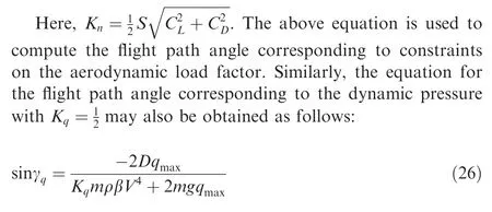
Reentry gliding vehicle has a feasible region in which it has to travel, known as the reentry corridor, which has higher and lower bounds. QEG constraint is the higher bound, and path constraints are the lower bounds. The maximum heating rate,aerodynamic load, and dynamic pressure are the path constraints that have to be enforced to ensure flight vehicle safety. The maximum values of the path constraints are defined as

Fig. 1 Bounds of cross-range corridor.
The value ofkQused is 9.4369×10⁻⁵.It is the heating rate at the stagnation point on the surface of the vehicle7with a curvature radius of 0.3048 m.
The variation in the path constraints can be seen through converting them into the limits of the altitude as follows:

The above Eq. (11) describe the boundaries of the reentry corridor. In the above equation,rQEG,r˙Q,rqandrnare the radial position vectors of QEG condition, maximum heating rate, maximum dynamic pressure, and the maximum aerodynamic load, respectively. The constants, ˙Qmax,qmaxandnmaxare the value of the constraints namely maximum heating rate,dynamic pressure, and aerodynamic load factor, respectively.
3.5. Terminal constraints
The reentry gliding vehicle has to attain the prescribed magnitude of the state parameters altitude,range to go and speed as per the initial conditions of the TAEM phase.These prescribed values are achieved through the objective function by using the proposed FPSOGSA method. The detail is explained in Section 3.3 with Eq. (9). There is another requirement known as the minimum value of heading angle offset, Δψd, as per Eq.(5).The desired offset is achieved with the aid of bank reversal logic. The detail to accomplish the heading angle accuracy is described from Eqs. (5) to (8) in Section 3.2.
4. FPSOGSA optimization method
A technique known as a Fractional-order Particle Swarm Optimization Gravitational Search Algorithm (FPSOGSA) is proposed in this research. In this proposed technique, the fractional-order calculus is employed for the position and velocity update of the swarm.
4.1. PSO algorithm
Kennedy and Eberhart in 199532first proposed a standard version of PSO to update the position and velocity of the swarm.The velocity is updated as follows:

wherep*andg*are the personnel and global best positions,respectively;c1andc2are the constants termed as cognitive and social coefficients, respectively; ε1and ε2are the random numbers. The coefficient ofvtis added as follows:

The coefficientwis a fractional number known as an inertia coefficient.Using the velocity equation,the update in the position of the swarm is as follows:

4.2. GSA algorithm
In the traditional GSA method,26,33the velocity of the swarm is updated as follows:
4.3. Novel FPSOGSA algorithm
The hybrid version of the PSO method and the GSA method is given as33,34

By using the magnitude of the inertia coefficient,w=1.The left-hand side of the above equation is the discrete form of the derivative. Fractional-order calculus is used to expand the left-hand side of the above equation as follows:

Eq.(19)is a hybrid form of the FPSO and GSA and termed as FPSOGSA.The equation describes that four previous terms are required to calculate the velocity of the swarm.The historical terms of the algorithm are helpful for global convergence.The standard versions of the FPSO and GSA are employed in different engineering applications. The proposed hybrid method is used to expedite the convergence and to improve the accuracy of the problem. Eq. (19) is used as an update scheme for the swarm particles by selecting the magnitude of the fractional coefficientb. For a specific problem, a complete range from 0 to 1 may be checked, and the value suitable for better convergence may be used. The full description of the FPSOGSA method for the trajectory planning of the reentry gliding vehicle can be seen from Fig. 2.
Fig. 2 Schematic diagram of FPSOGSA method.
4.4. Oscillation suppression QEG scheme
The mission analysis of the lifting vehicle realized the state variable(flight path angle)has oscillations,causing the oscillatory behavior in the other state variables the altitude and the in path constraints.31,35These oscillations resulted in ineffectiveness in the control system design during the lower peaks of dynamic pressure. The proposed scheme aims to aid the flight vehicle to fly within a QEG condition to avoid the abrupt change in the aerodynamic heating and aerodynamic loads so that the burden of the control system is released. In this scheme, bank angle command is used by regulating the flight path angle as feedback signals.The method proved to be quite efficient by commanding the bank angle to generate a suitable lift, which is useful for the vehicle to glide for the required range.
The flight path angle should be nearly zero or fluctuate very slowly for the gliding flight. Considering, ˙γ ≈0, cosγ ≈1, and overlooking the Earth rotation rate resulted as below:
Comparing the above with that of the equation of motion resulted in the following

The QEG condition is enforced through the computation of the corresponding flight path angle from the above equation.
The commanded bank angle is computed from the modulation of the flight path angle as follows:

Here,σnomis the nominal,and σcmdis the commanded bank angle, respectively. The feedback gaink>0,varies as a linear function of speed.31The oscillations from the state variables and the path constraints are eliminated by using the commanded bank angle computed from Eq. (23). After the elimination of the oscillation, the bank angle control profile calculated above is utilized to integrate the equation of motion to compute the feasible trajectory for the entire flight.
4.5. Load factor/dynamic pressure constraints
The excessive heating rate constraints are avoided,through the scheduling of the angle of attack. To prevent the extreme values of the aerodynamic load and the dynamic pressure path constraints, a method is proposed. In this method, we use the slope of the altitude velocity curve corresponding to the maximum aerodynamic load.The aerodynamic load is defined

The above equation gives the slope of the altitude velocity curve.By comparing it with the slope obtained from the equation of motion, after simplification, we can get

The bank angle command to enforce the path constraints is described through the following equation:

Here, γn,q=max(γn,γq). By using Eq. (27), a bank angles command is generated through the computed flight path angle to satisfy the maximum aerodynamic load/dynamic pressure constraint. The value of the gainKn,q>0 is appropriately selected because its higher value causes the oscillations in the control variable, and its lower value may cause poor tracking of the path constraint. Eq. (27)is used for the computation of the commanded bank angle corresponding to the violation in the path constraints (aerodynamic load/dynamic pressure). If path constraints are not violated, the QEG scheme is utilized to compute the commanded bank angle. From the bank angle computed above, along with the angle of attack profile, we integrate the equation of motion for the complete flight to achieve the desired objectives.
4.6. Constraints handling by FPSOGSA algorithm
The proposed FPSOGSA algorithm handles all the constraints,including the QEG condition,terminal,and path constraints. Each particle of the swarm acts as an initial bank angle, the optimum values of the Mach number, and the optimum angle of attack during each iteration. By using the optimum initial bank angle, the instantaneous bank angle is used to modify the QEG condition. The QEG condition eliminates the oscillations in the state parameters and also from the path constraints. Bank angle command, along with the bank reversal logic,is used to integrate the equation of motion to accomplish the desired objectives. Bank angle command is further modified from that of the QEG value if the load factor or dynamic pressure path constraint violates. The optimum values of the Mach number and the angle of attack are used to compute the angle of attack profile through the optimization process. The control profiles obtained through the proposed FPSOGSA algorithm are utilized to integrate the equation of motion of the reentry vehicle and thus to calculate objective function for every particle. The best objective function among all of the particles is retained during the iterations. This process continues upon the termination condition. In the end,the required optimized parameters,initial bank angle,the optimum values of the Mach number, and the optimum angle of attack are obtained to evaluate the control profiles. By utilizing these control profiles, the equation of motion is integrated between the initial and the final point by satisfying the path and terminal constraints to achieve the desired objectives.The detail of the FPSOGSA algorithm for constraint handling is shown in Fig. 2.
5. Simulation performance
Simulation performance is assessed based on the results explained in this section.
5.1. Simulation conditions
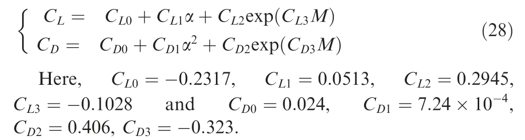
The CAV is the conceptual vehicle that follows the gliding flight during the reentry in the Earth atmosphere.The concept of CAV is to survive the atmospheric entry by reducing its Mach number to the lower value and dispense the payload into the atmosphere.2There are two types of CAV vehicles from which CAV-H is used for analysis. The vehicle has a mass of 907.2 kg, and its reference area is 0.4839 m2. The maximumL/Dratio of the vehicle is about 3.5. The aerodynamic coefficients of lift and drag for the CAV-H are calculated from the angle of attack by the following fitting equation36:
Simulations are performed based on the initial and final conditions, as shown in Table 1. The initial conditions are based on the dispersion in the reentry parameters,31whereas the terminal conditions are values of the state parameters at the TAEM interface.
The values used for the simulation purpose of the tuning parameters are as follows:
The population sizeN=20, the maximum number of iterations itermax=20, the value of the cognitive coefficientc1=0.5, social coefficientc2=1.5, and coefficientb=0.5,respectively.
The purpose of the reentry trajectory optimization is to calculate the control profiles. For the computation of the profile,the problem is converted into the search of the three design variables. These three variables are the initial bank angle σ0which is used in the calculation of the bank angle profile, the critical values of the angle of attack αopt,and the critical value of the Mach numberMoptwhich is used to calculate the angle of the attack profile. The bounds used for these design variables are 0 to 90 degree,12 to 18 and 10 to 20 degree for initial bank angle σ0, critical Mach numberMopt, and the critical angle of attack αopt, respectively.
The results during the optimization process are generated with the aid of the 2016 version of the Matlab. The enhancement in computational efficiency is realized with the aid of software like C++. In the research, the optimization results are computed by using the Acer laptop with Intel® Core i3 CPU, having a processor speed of 2.53 GHz and RAM capability of 4.00 GB.
5.2. Simulation requirements
The requirement is to compute a flyable and smoother trajectory for the gliding reentry vehicle from the reentry interface to the TAEM point with prescribed accuracy in the state variables, to enforce the path constraints, and to force the flight vehicle within the prescribed cross-range error. The allowable errors in the final state, velocity, altitude, and downrange are ΔV≤±50 m/s, Δh≤±2 km, and Δsgo≤±10 km, respectively.37The corresponding path constraints, the aerodynamic load factor, heating rate, and the dynamic pressure are 1.65g,4 MW/m and 53 kPa,respectively.The final cross range error,ΔCRf, should be in accordance with Eq. (5).
5.3. Baseline method
Results based on the baseline method by using the proposed FPSOGSA method are analyzed in this section. The control profiles based on the proposed method are shown in Fig. 3.Fig. 3 describes that the value of the bank angle maintains as zero until a specific aerodynamic acceleration (5 ft/s2) and corresponding dynamic pressure are achieved.31The state parameters and path constraints are shown in Fig. 4. Fig.4(a)and(b)show that state parameters have oscillations,which is a trait of the higherL/Dflight vehicle. These oscillations, in turn, produce oscillations in the aerodynamic load, dynamic pressure, and the maximum heating rate path constraints, as seen in Figs.4(c)and(d).The baseline method has oscillations in the state parameters and in path constraints, causing the violation of the path constraints; however, the accuracy in the terminal state parameters is achieved by using the baseline trajectory planning method.
5.4. Computational analysis
The computational analysis compares the proposed FPSOGSA, standard versions of the PSO, and the GSA method to validate the computational efficiency of the FPSOGSA optimization algorithm. In the analysis, all of the methods calculate the control profiles from 100-independent runs of the simulations. Three design variables, along with the objective function, the number of iterations, and the computation time, are compared in Tables 2 and 3. The comparison results are presented based on the worst and the best objective functions.
The proposed FPSOGSA method is converged earlier with shorter computation time, as seen from Tables 2 and 3. The proposed method converged in 9-13 iteration as compared to 14-16 iteration for the standard PSO method and in 9-16 iteration for the standard GSA method, respectively.

Table 1 Initial/final conditions.
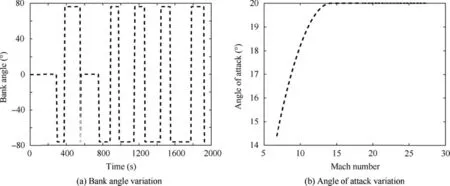
Fig. 3 Control profiles based on the proposed method.

Fig. 4 State parameters and path constraints.

Table 2 The best objective function, optimization results.
Tables 2 and 3 further show that the computation time for the optimization process by using the proposed FPSOGSA method is shorter than that of the PSO method. Although the GSA method converges earlier, it has a larger value of the objective function, which shows its inaccuracy and trapping in the local minima. Based on the analysis presented above,it is clear that the proposed FPSOGSA technique has better,earlier, and more accurate convergence property in comparison to the standard PSO and GSA algorithms.
The convergence analysis resultant to the best objective functions among the entire 100-run is shown in Fig.5 for comparison. The figure shows that the proposed FPSOGSA method converges earlier in the fewer number of the iterations in comparison to the PSO and GSA methods.
5.5. Statistical analysis
The statistical analysis in Table 4 is based on the parameters,including the number of iteration, computation time, and objective function for the entire 100-runs which are compared.The results of the table show that the proposed FPSOGSA method has superior mean values of iteration number for all the cases. It is also observed that the standard deviation of the FPSOGSA method is better due to the use of the four historical values used in the computation.The comparison of the objective function shows that the proposed FPSOGSA method has better mean and standard deviation for all the cases presented. In the case of the computation time, the mean value of the proposed method and standard deviation of the FPSOGSA method is better, which shows that the proposed approach converges earlier as compared to the other two techniques.
A statistical analysis based on the Mann-Whitney U test is performed on the three algorithms. Thep-value calculated from the methods approaches to zero for the significance level of 0.05. Based on the p-value, it is concluded that the null hypothesis may be rejected corresponding to a significance level of 5%, and there is a significant difference in the performance of the algorithms. The results based on statistical analysis show that the FPSOGSA method performs better as compared to the other methods.
Thus it is concluded based on the analysis of 100 runs of the simulations that the proposed FPSOGSA technique may be employed to compute the feasible and smoother reentry trajectory from the reentry interface to the TAEM point.This trajectory enforces the path constraints and achieves the terminal accuracy in state constraints.
5.6. Oscillation suppression scheme
A scheme is devised based on the QEG condition by scheduling the bank angle from Eq.(23)for oscillation suppression in the state parameters to achieve the smoothness in the trajectory. In this scheme, the proposed FPSOGSA method is used to calculate the control profiles by searching the initial bank angle, optimum values of the angle of attack, and the Mach number. By using these calculated control profiles as inputs,the reentry trajectory is generated from the initial to the final point. The results of the QEG method are compared with the baseline method for the mission in Table 1. The output results are shown and compared in Fig. 6. It is seen from the results in the figuresthat there are oscillations in the state parameters by using the basic method, which is removed by using the modified QEG scheme. There are also oscillations in the path constraints with several minima and maxima, as shown in Figs.6(d)-(f), which are also eliminated by using a modified QEG method.Although,after removal of the oscillations, the maximum value of the aerodynamic load path constraint is lowered, its strict enforcement is not achieved.Thus,it is concluded from this section that the oscillation suppression scheme based on the QEG condition effectively achieves the accuracy in state constraints and partially enforces the path constraints.

Fig. 5 Convergence comparison among FPSOGSA, PSO, and GSA.
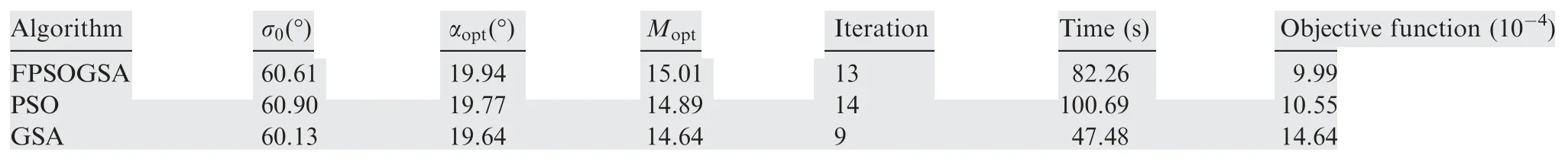
Table 3 The worst objective function, optimization results.
5.7. Aerodynamic load/dynamic pressure management
The maximum heating rate path constraint is enforced through the objective function by using the angle of the attack profile.The following section demonstrates the aerodynamic load factor and dynamic pressure management scheme.The criteria of the management scheme must be technically rigorous, practical,computationally efficient,precise,and robust.7The oscillation suppression scheme significantly improves load management. The management of aerodynamic load factors and the dynamic pressure is further enhanced by employing the load management scheme to calculate the optimal control profile based on the proposed FPSOGSA method.For the calculation of the control profile, the number of the design variables is three, termed as optimum initial bank angle, critical values of the angle of attack,and the critical value of the Mach number. By using the control profile computed from the best objective function, the variation of the state variables and the path constraints is shown in Fig.7.The results in the figure shows that the control variable bank angle is commanded at 0 degree until the total aerodynamic acceleration achieves a particular prescribed threshold value to aid the effectiveness of the aerodynamic control. Bank angle magnitude is suddenly decreased afterward due to an increase in the lift force. Its magnitude varies as a function of specific mechanical energy height afterward. Bank angle profile also reverses its direction whenever the cross-range touches its limit.The oscillations are efficiently eliminated by QEG condition, and the bank angle commanded according to this condition until the aerodynamic load, or dynamic pressure constraint violates. During the violation period of the path constraints, the bank angle is commanded according to the constraints enforcement scheme. It is observed from Fig.7(a) that there is a slight oscillation at the later part of trajectory due to the feedback gain. These oscillations become prominent if we use the higher values of the feedback gain, whereas lower value causes poor tracking of the path constraints.Therefore it should be selected in such a way that there should be a balance between oscillation and better tracking.

Table 4 Statistical analysis.

Fig. 6 The output results are shown and compared.
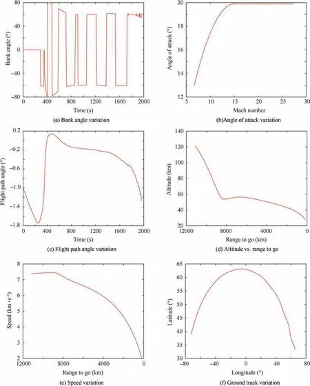
Fig. 7 The variation of the state variables and the path constraints.
Fig.7(b)shows that the angle of attack remains constant at its optimum value up to the optimum value of the Mach number, after which it falls monotonically. Fig.7(c) shows that there is an increase in the flight path angle whenever the aerodynamic load /dynamic pressure path constraint becomes active. Figs.7(c)-(f) show that the state parameters are smoothed after the elimination of the oscillations by using the QEG scheme. It is also seen from Figs.7(h)-(j) that the optimum trajectory based on the proposed FPSOGSA method effectively enforces the path constraints by using the constraint enforcement scheme,causing the flight vehicle to fly within the reentry corridor to ensure its structural integrity.
Thus, based on the analysis in the section, it is concluded that the path constraints management scheme efficiently achieves the enforcement of the path constraints.

Fig. 7 (continued)
5.8. Computational time impact
The impact of the computational time on the trajectory is analyzed in this section.As the flight vehicle is a flying body rather than a static object, it may be thought that the computational time may cause a delay in the trajectory of the flight vehicle.It is mentioned in the preceding section that the bank angle is commanded as a zero degree until the threshold dynamic pressure corresponding to the aerodynamic load of 5 ft/s is achieved.The optimal angle of attack is maintained at its maximum value during the trajectory up to around 1400 s. The commanded bank angle is maintained at zero degree up to 250-300 s, as shown in Figs.3(a),and 7(a). It means that, for the subject trajectory, the computation time will not cause any delay in the trajectory up to 250 s. From Tables 2-4, it is seen that the computational time to generate the control variables profiles varies from 55 to 82 s,with an average value of 66 s.As the worst computational time for the optimal trajectory by using the proposed method is approximately 82 s, it is concluded that the computational time will not cause any delay in the trajectory of the flight vehicle.
5.9. Terminal accuracy analysis
Terminal accuracy is accessed based on the requirement, as given in Section 5.2. Table 5 shows the state parameter errors corresponding to the best and the worst objective functions.The errors in the state parameters: altitude, speed, range to go, and the cross-range are as per the terminal constraints accuracy requirement at the TAEM interface.
Thus, based on the terminal accuracy analysis in the section, it is established that the proposed FPSOGSA method accomplishes the required accuracy in the terminal constraints.
5.10. Dispersions in entry interface
The performance of the proposed FPSOGSA algorithm is accessed for the dispersion case in the initial state parameters at the entry interface. The dispersion in the initial altitude,speed, and flight path angle is considered with the values of±2 km, ±30 m/s, and ±0.2º, respectively. The nominal angle of attack profile with the load factor of 1.65gand the dynamic pressure of 53 kPa is used for the missions described in Table 1.The optimization problem is to find the bank angle profile by optimizing the initial bank angle and by using the energy parameterization method afterward. The simulation results based on the proposed trajectory optimization method are shown in Figs.8(a)-(d). The Figs.8(b)-(d) show that all of the path constraints are enforced for the dispersion in the entry interface. The corresponding output errors in the terminal states which are shown in Table 6 are of the same quality of accuracy as in the case of the nominal mission.

Table 5 Output state errors from FPSOGSA method.

Fig. 8 The simulation results based on the dispersion in the entry interface.
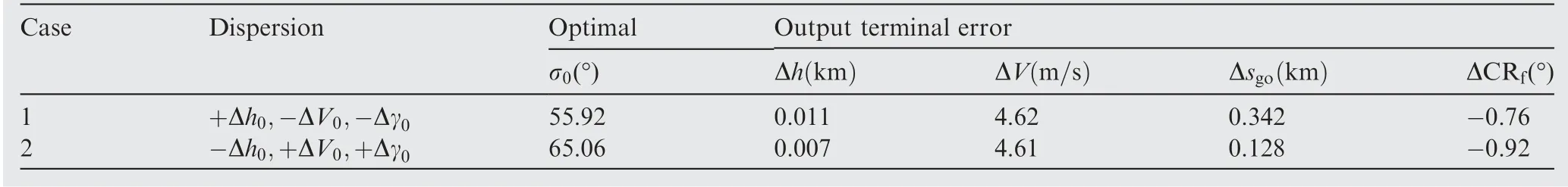
Table 6 Entry interface dispersions, optimal parameters, and output errors comparison
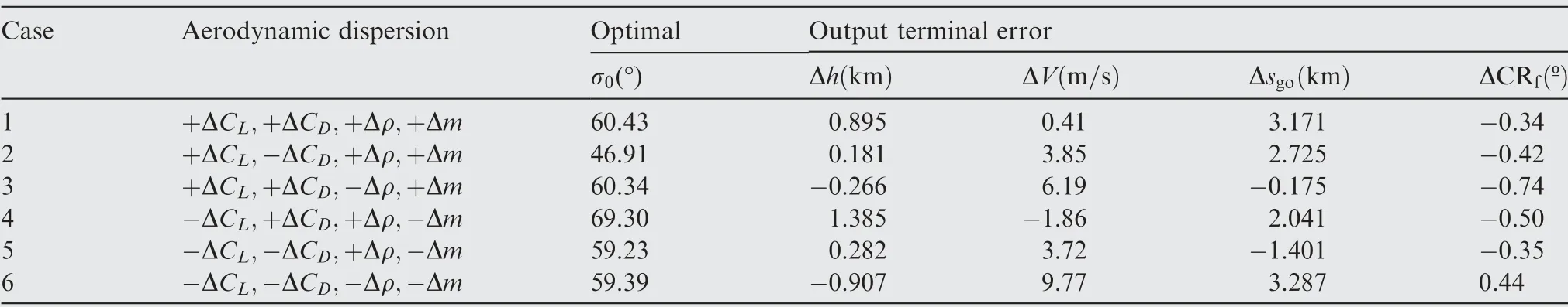
Table 7 Optimal/output results comparison of aerodynamic and atmosphere dispersions.
5.11. Dispersions in environmental conditions
The performance of the proposed FPSOGSA method is accessed for the dispersion in the environmental conditions.A dispersion value of ±10% is used for the analysis purpose in the atmosphere density, aerodynamic lift, and drag coefficient, whereas the dispersion of ±5% is considered for the vehicle mass. These dispersion values are maintained constant throughout the trajectory. The dispersion in the parameter, including the aerodynamic lift and drag coefficient, atmospheric density, and the vehicle mass, is used for the analysis whose different combinations are shown in Table 7. The angle of attack profile with the aerodynamic load value of 1.65gand the dynamic pressure value of 53 kPa is used as described in Table 1. The simulation results based on trajectory optimization using the proposed algorithm are shown in Fig. 9. It is seen from the figures that, by following the optimal bank angles and the nominal angle of attack profile, the path constraints are tracked efficiently. It is further seen that the constraint of the dynamic pressure remains lower than the maximum value for all the cases, except for the Case-2 (see Fig.9(b)), where this constraint is tracked efficiently by the proposed algorithm.Table 7 shows the errors in the output state parameters. It is seen from Table 7 that the errors in altitude, speed, and downrange for the dispersion case achieve the same level of accuracy requirement as in the nominal case.
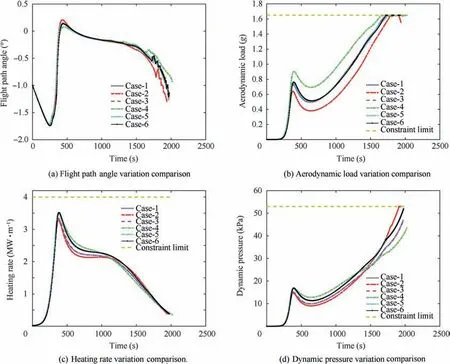
Fig. 9 The simulation results based on the dispersions in the environmental condition.
5.12. Robustness analysis
Different missions having different initial and final latitude/-longitude are considered to check the robustness of the proposed FPSOGSA algorithm. The simulation results are generated according to the inputs described in Table 8,and the outputs are shown in Fig. 10. Based on the control profiles as shown in Figs.10(a) and b), the state parameters show the smooth trajectory as shown in Figs.10(c)-(f).Fig.10(c) showed that the flight path angle increases slightly during the tracking of the constraint. It is further seen from Figs.10(g)-(j) that all the path constraints are enforced, thus ensuring the flight vehicle safety of the higherL/Dreentry vehicle.

Fig. 10 The simulation results based on the robustness analysis.
By using the control profile based on the trajectory optimization method from the proposed algorithm, the output results are shown in Table 9.It is seen that the proposed algorithm achieves the objectives of minimum errors in the terminal state constraints.
Thus,based on the results,it is concluded that,by using the optimal angle of attack profile and modulation of the bank,angle achieves the prescribed terminal errors in state parameters forallthecases andenforcesthepath constraintsfor allthecases.
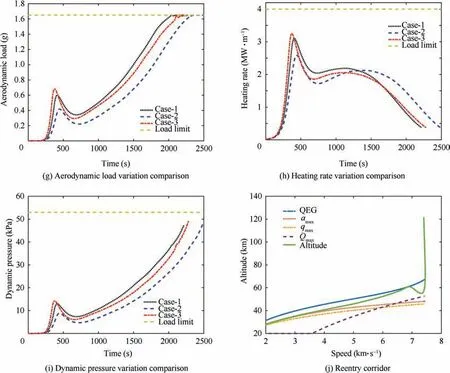
Fig. 10 (continued)
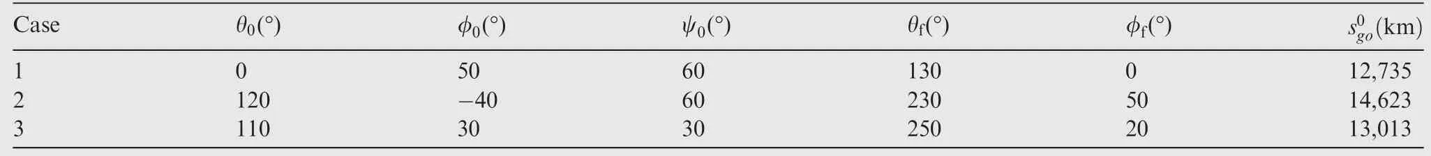
Table 8 Different latitude/longitude missions for robustness analysis.
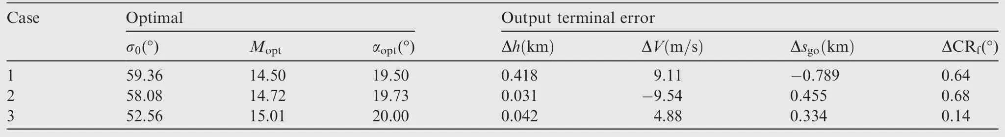
Table 9 Output parameter errors for robustness analysis.
6. Conclusions
Trajectory planning of the hypersonic reentry gliding flight vehicle is performed by proposing a hybrid heuristic optimization method known as the FPSOGSA method. FPSO method is used to achieve accuracy, whereas the GSA method is used for earlier convergence. By using the proposed method, the control variables profile is computed. Based on this control profile,a trajectory for the gliding reentry flight vehicle is generated from reentry point to TAEM interface to check two objectives. These objectives include the smoothness in the trajectory with prescribed terminal accuracy and the enforcement of the path constraints.
Simulation results are performed by considering the CAV-H flight vehicle.The results show that the terminal accuracy at the TAEM interface is satisfied by using the proposed baseline FPSOGSA method.However,the path constraints are not met due to the presence of the phugoid oscillations in state parameters, which are eliminated by using a modified QEG scheme.The simulation results by employing the QEG scheme show that thetrajectoryissmoothedwhilethepathconstraintsareenforced partially. The path constraint enforcement scheme is applied through the further modification of the proposed FPSOGSA method. The results show that the scheme efficiently enforces path constraints.Thus based on the results,it is concluded that the proposed method achieves its two objectives of smoothness of the trajectory and the enforcement of the path constraints.
The terminal accuracy and the computational efficiency from the proposed FPSOGSA method are calculated and compared with that of the standard PSO and the standard GSA method. The comparison results show that the proposed method has better accuracy via its objective function and earlier convergence via its computation time/iteration number. The proposed FPSOGSA method is also applied for certain dispersions and off-nominal conditions,which shows a similar quality of accuracy as in the nominal case. Different downranges are also tested for the robustness, which are also depicted with the same quality of results as in normal conditions.
Thus,trajectory planning by using an efficient optimization algorithm for hypersonic gliding reentry flight vehicle to ensure its structural and thermal safety is the outcome of this study.In the future,the proposed method may be improved by applying it for the low and mediumL/Dratio. The improvement in the atmosphere and the gravity models may also be made in the future.
Declaration of Competing Interest
The authors declare that they have no known competing financial interests or personal relationships that could have appeared to influence the work reported in this paper.
杂志排行

CHINESE JOURNAL OF AERONAUTICS的其它文章
- Tangling and instability effect analysis of initial in-plane/out-of-plane angles on electrodynamic tether deployment under gravity gradient
- Aerodynamic periodicity of transient aerodynamic forces of flexible plunging airfoils
- Effects of swirl brake axial arrangement on the leakage performance and rotor stability of labyrinth seals
- Experimental and computational investigation of hybrid formation flight for aerodynamic gain at transonic speed
- Tomography-like flow visualization of a hypersonic inward-turning inlet
- A theoretical and 1-D numerical investigation on a valve/valveless air-breathing pulse detonation engine