Aerodynamic periodicity of transient aerodynamic forces of flexible plunging airfoils
2021-03-16ZHOUChoZHANGYnliWUJingho
ZHOU Cho, ZHANG Ynli, WU Jingho,*
a School of Aeronautics Science and Engineering, Beihang University, Beijing 100083, China
b School of Transportation Science and Engineering, Beihang University, Beijing 100083, China
KEYWORDS Aerodynamic periodicity;Flapping wing;Flexibility;Micro-air vehicle;Vortex structure
Abstract For flapping micro-air vehicles, periodical aerodynamics in every plunging period is always desired in the design of aircraft controlling system.During the periodic plunges of rigid airfoil,either periodical or non-periodical aerodynamic forces can be generated.Real airfoils are usually flexible so that the effect of flexibility on unsteady characteristics of aerodynamic periodicity should be considered. In this study, a fluid structure interaction analysis is employed to systematically investigate the aerodynamic periodicity of a periodically plunging flexible airfoil. The influences of several dimensionless kinematic and structural parameters on aerodynamic periodicity are investigated.The results show that the aerodynamic periodicity of plunging flexible airfoil qualitatively resembles that of rigid airfoil as the mechanisms contributing to aerodynamic periodicity are kept for airfoil with various flexibilities. However, aerodynamic periodicity at small plunging amplitude and high Reynolds number can be improved as airfoil becomes medium flexible but worsened as airfoil is very flexible. The reason is that the deformation of the airfoil changes the strength and structure of the nearby vortices,thereby leading to weak vortex-vortex and vortex-airfoil interactions. The extent of improvement in aerodynamic periodicity is also found significantly influenced by incoming velocity.
1. Introduction
The aerodynamic of a flapping wing is a major research topic among biologists and aeronautical engineering technologists.Previous considerable literature1-3revealed the complex fluid mechanism and aerodynamic performance of a flapping wing system,thereby significantly enhancing people’s understanding on natural flyers and swimming fishes and effectively promoting the development of man-made flapping devices.Currently,the general aerodynamic performance of flapping wing, especially propulsive performance, varying with wing kinematic parameters has been roughly addressed.1-6With the deepening of research in this field,some interesting fluid phenomena have been discovered and gradually attracted researchers’ interests;one of these phenomena is the produced periodical and non-periodical aerodynamic forces during the periodic plunging of airfoil.7-9
Although a periodically plunging motion definitely leads to periodical aerodynamic force production in terms of a long time scale, plunging airfoil or flapping wing sometimes produces non-periodical aerodynamic forces in terms of short plunging periods (e.g. ten periods).10Many experimental and numerical studies confirmed the existence of this phenomenon with the variation in vortex topology.7-9Tay and Lim11excluded the possibility that this phenomenon is caused by factors such as numerical computational parameters.Natural flyers or man-made flapping devices(e.g.,micro-air vehicles)may have difficulty achieving robust control and smooth operation when non-periodical aerodynamic forces are produced in their flying or operation. Therefore, the non-periodical status of aerodynamic forces should be avoided and the mechanism behind such phenomenon should be determined.
Some researchers emphasized the effects of dimensionless variables on the periodicity of aerodynamic forces and proposed various periodical boundaries. Lewin and Haj-Hariri12examined an elliptic airfoil under prescribed periodical plunge motions at a zero angle of attack given differentkandkhvalues,wherekis the reduced frequency andkhis the dimensionless velocity. They found that non-periodical cases are usually observed in the region with a high value ofkandkh.An experimental study conducted by Lentink et al.9on a periodically pitched and plunged airfoil models illustrated another periodicity-and-non-periodicity boundary. Their study indicated that a periodical vortex wake is produced only when pitching amplitude and dimensionless plunging amplitude are adequately large. Ashraf et al.8investigated a flapping NACA0014 airfoil and reported that the flow can be transformed from periodical to non-periodical status if the Reynolds numberReincreases from 1100 to 20,000. Although the aforementioned work revealed several variables influencing aerodynamic periodicity, their study did not cover all the dimensionless parameters that determine the aerodynamic forces of a plunging airfoil. Therefore, a systematic investigation on the effect of dimensionless kinematic variables on the periodicity of aerodynamic forces is further conducted by Wu et al.10They found that the aerodynamic periodicity is significantly dependent onReand plunging amplitude,and a criterion parameter combining the two factors is proposed to judge whether a case is periodical.The transformation of aerodynamic periodicity, as presented in the aforementioned literature, is also accompanied with significant variations in the vortex topology around the airfoil. Several typical vortex patterns,7,13,14such as dissipated wake, anti-von Karman vortex street, deflected wake, and non-periodical wake, can be observed in case of different kinematic parameters.As the vortex becomes non-periodical,enhanced vortex-wake interaction causes the aerodynamic forces to be non-periodical.13
In reality, wings of natural flyers and man-made micro-air vehicles are usually of light weight and high flexibility; therefore, they deform significantly with the action of aerodynamic pressures and inertial forces during wing flapping.The passive deformation of wing in turn affects the production of aerodynamic forces. Therefore, in the last two decades, the role of wing flexibility on flapping aerodynamic has been discussed intensively. Heathcote et al.15investigated the effect of chordwise flexibility on the aerodynamic performance of a purely plunging airfoil under hovering conditions.The force measurements showed that the airfoil flexibility has a strong relation with its thrust. At high plunge frequencies, the highest airfoil thrust coefficient is achieved with intermediate stiffness, while the least stiff airfoil can generate large thrust at low frequencies. An optimum airfoil stiffness is found for a given plunge frequency and amplitude. Other works on 2D plunging airfoil and 3D flapping wing also verified this conclusion.16-18According to numerical or experimental results shown in considerable literature, flexibility also significantly influences the instantaneous aerodynamic forces apart from impacting time-averaged aerodynamic forces. In most cases, the amplitude of aerodynamic forces of flexible airfoil decreases compared with rigid airfoil.19Given that the production of aerodynamic forces is tightly related to vortex field, vortex field must undergo obvious changes simultaneously.Heathcote et al.15revealed that the amplitude and phase angle of motion of the trailing edge affect the strength and spacing of the vortices, as well as the time-averaged velocity of the induced jet.Lai and Platzer14and other authors7,13revealed that the wake produced by a purely pitching airfoil presents either symmetry breaking status or deflected breaking status. As the wing becomes flexible, flexibility can trigger20and inhibit20,21the symmetry breaking property of wake; the reason is mainly due to the different strengths of vortex circulation caused by wing flexibility.21Numerous studies3confirmed that flexible wing can effectively affect aerodynamic forces, but only a few works focused on its effect on aerodynamic periodicity.Although some work considered the changes in flow structure around a plunging airfoil due to wing flexibility,the flow structures in most cases are still periodical. Therefore, the mechanism of the change in aerodynamic periodicity with wing flexibility is unclear and requires further systematic study.
In our previous studies,we explored the periodicity of aerodynamic forces produced by a periodically plunging rigid airfoil10and also considered the influence of flexibility on aerodynamic performance using a Fluid-Structure Interaction(FSI)analysis.19To follow up these investigations,the aerodynamic periodicity of flexible airfoil was numerically analyzed in current study. Aerodynamic periodicity of three airfoils,that is rigid, flexible and very flexible airfoils, were computed first and the changes in aerodynamic periodicity as airfoil became flexible were addressed. The time courses of aerodynamic forces and vortex variation were also analyzed to further explain the mechanism of the change in airfoil aerodynamic periodicity with wing flexibility. The effect of advance ratioJon aerodynamic periodicity of flexible airfoil was discussed in the final.
2. Material and methods
2.1. Models
For simplification, a flat airfoil with half circles in Leading Edge(LE)and Trailing Edge(TE)was studied.Two rectangular coordinate systems,an inertial coordinate systemOXYand a body-fixed coordinate systemoxy, were introduced to describe the periodically plunging motion and passive deformation of airfoil, respectively (Fig. 1). The originOinOXYcoincides with the plunging position of airfoil in the middle position of an upstroke.AxesOXandOYare parallel and vertical to the horizontal direction, respectively. The bodyfixed coordinate systemoxymoves with airfoil. Its originocoincides with the plunging position of airfoil, and the axisoxis along the mean camber line when the airfoil is not deformed (the dotted line in Fig. 1).
Same as our previous studies,10,19airfoil plunged vertically in a time-harmonic function against a constant horizontal freestreamU∞at a constant angle of attack α0. The plunging motion inOYdirection described inOXYis given as

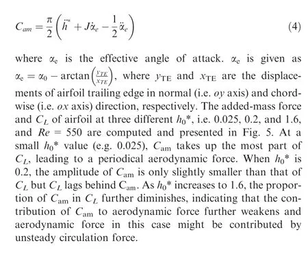
wherehdenotes the plunging displacement, which equals the displacement of LE (i.e.YLE);h0andfrepresent the plunging amplitude and frequency, respectively;tis the physical time.Passive deformation of the flexible airfoil is computed numerically. The effective angle of attack αeis changed as airfoil deforms. αeis given aswhereyTEandxTEare the displacements of airfoil trailing edge in normal(i.e.oyaxis)and chordwise(i.e.oxaxis)direction,respectively.
Airfoil kinematic is non-dimensionalized following our previous work. The mean velocity of plunging motionUref(=4h0f) and chord lengthcare used as the reference velocity and the reference length, respectively. The reference timeTrefis then computed asc/Uref. Accordingly, plunging amplitude,deformation displacement, and freestream velocity can be non-dimensionalized ash0* =h0/c,y* =y/c, and advance ratioJ=U∞/Uref,respectively.Aerodynamic forces of a periodically plunging flexible airfoil are influenced by four kinematic parameters (i.e.,Re,h0*, α0, andJ). The scales of four kinematic non-dimensional parameters are the same as those of a previous work.10Reranges from 70 to 5000,h0* ranges from 0.05 to 1.6, andJranges from 0 to 1.0. Given that α0slightly affects airfoil aerodynamic periodicity,10its value is set as 20° in this study.
2.2. Methods
2.2.1. Fluid-structure interaction solving procedure
A loose coupling FSI solver, which has been widely and successfully applied in solving numerous FSI problems, is performed to compute airfoil flexible deformation. The loose coupling method allows the use of existing mature Computational Fluid Dynamic (CFD) and Computational Solid Dynamics (CSD) solvers and only needs to develop an FSI interface for exchanging aerodynamic pressures and deforming displacements of the airfoil surface between the two solvers.In this paper, the FSI solver was built based on a home-made CFD solver with the ANSYS finite element program. A detailed introduction of the algorithm how the solver conducted can be referred to in our previous work.19In this FSI method, an implicit scheme is used and in each physical time step, CFD and CSD solvers are called one after another until the solution converges. Given that implicit scheme requires high time and computational costs, two measures are taken to accelerate the convergence in a physical time. The first is to predict deforming displacement at the beginning of a subiteration,22thereby ensuring the initial deforming displacement approach of the final solution. In addition, Aiken Δ2method23,24for computing ωmis introduced to accelerate the convergence of sub-iteration.
The equations governing the flow around the airfoil are the 2D incompressible unsteady Navier-Stokes equations, which are written in the inertial coordinate systems in the following dimensionless form:


Fig. 1 Coordinate systems and airfoil kinematics.
where u is the velocity vectors, andpis the static pressure.StandReare defined asc/(UrefTref) andUrefc/υ, respectively,where ρ is the fluid density and υ is the kinematic viscosity coefficient. BecauseTrefis taken asc/Uref,Stalways equals 1. The artificial compressibility method developed by Rogers et al.25,26is employed to derive the velocity and the pressure in the flow field around the airfoil using a deformedOgrid.Details of the flow solver and grid were provided in a previous study.10,19After each physical time converges, aerodynamic forces (i.e., dragDand liftL) can be computed by integrating pressure and the viscous forces over the airfoil. Drag and lift coefficients can be computed asrespectively.
The deforming displacement of airfoil is computed by a transient analysis using the commercial software ANSYS in the body-fixed coordinate system. When airfoil becomes very flexible, its transverse deforming displacement is so large that the effect of non-linear deformation should be considered.Therefore, large displacement and non-linear effect are always considered in the transient analysis for all the cases in this study. The airfoil is simplified using a cantilever beam with forced displacement in LE and modeled by a beam element (i.e. beam 3). The implicit time integration algorithm in ANSYS called the Newmark method is used to ensure numerical stability in the structural non-linear analysis.CSD grid is considered the same as CFD grid on airfoil surface to reduce numerical error during the transfer of aerodynamic pressure and structural displacements between the CFD and CSD solvers. Key parameters determining the deforming displacement of airfoil and consequently influencing the aerodynamic forces of airfoil are beam relative thicknessb*, density ratio between structural and fluid densities ρ*and effective stiffness Π.Π is defined using Young’s modulus of the materialEasEb*3/(12ρU2refc3). From the study of Heathcote et al.,15,27three airfoils with different flexibility,that is very flexible, flexible and rigid airfoils, are considered,whose Π is 0.45, 4.5 and ∞(rigid airfoil), respectively. MAV wing moves in the air and the density ratio between wing structure and air is almosto(103),19and therefore we set the high density ratio a constant value, i.e. ρ*=1000. All of the non-dimensional parameters and their scale of values are summarized and listed in Table 1.

Table 1 Non-dimensional parameters and their scale of values.
2.2.2. Criterion evaluating aerodynamic periodicity
The normalized root mean square (rms) criterion, which was used in a previous work,10is still introduced in this study to quantitatively determine whether a case is periodical or nonperiodical. rms is defined as

whereAiis half of the difference between the maximum and minimum of the aerodynamic force (CLorCD) within theith plunging period,nis the number of observed plunging motions,andis the average value ofA1,A2,...,An.rms evaluates the fluctuation ofCLandCD. A large value of rms indicates a high fluctuation and poor periodicity of aerodynamic force. The aerodynamic forces for each case are computed in 40 flapping periods to obtain a fully developed flow. rms ofCLandCDare computed based on the result of the last 10 successive periods. If the rms values ofCLandCDare smaller than 0.01, then the case can be considered periodical; otherwise, the case can be considered non-periodical.
2.3. Method validation
2.3.1. Grid test
The computational code and the grid models are validated to ensure the rationality of the simulation. Grid density, computational domain size,and time step are verified. In our last literature,10grid used to emulate a plunging rigid airfoil is tested.To further verify grid-independence of the FSI simulations,we performed grid test on the basis of our previous work.10Parameters in test case are selected asRe=350,h0* = 0.1,α0=20°,J=0, Π=4.5, and ρ* = 1000.
The time courses ofCLandCDcomputed using three grids with different densities in a flapping cycle are plotted in Fig.2.The nodes of the three grids are 100×161 (in the normal and chordwise directions, respectively, for grid 1), 151×241 (for grid 2), and 200×325 (for grid 3). The outer boundary is located 40caway from the airfoil surface. The grid distances near the airfoil are 10-4, 10-4and 5×10⁻⁵. A time step of 400 in a flapping cycle is used in the computation. Nondimensional timeis defined to describe the time courses of airfoil motion during one flapping cycleclearly.=0 and=1 indicate the start of the downstroke and the end of the upstroke, respectively. Fig. 2 shows that the time courses of the force coefficients for grids 2 and 3 are similar and the computational results for grid 1 deviate slightly from those for the two other grids. In order to capture the subtle structure in the flow field, the mesh density of grid 3 is selected and the computational domain size and time step are further validated based on grid 3.The computational domain size and time step are proposed to be 40cand 400, respectively, in one flapping cycle in this study.In summary,the preceding analyses indicate that grid 3 with 400 time steps in one flapping cycle is appropriate and therefore selected for all the cases in this study.

Fig. 2 Computed results in one plunging period by different grids.
2.3.2. Comparison of simulation and experimental results
The computational code is validated to ensure the rationality of the simulation. In previous study,10code validation for a plunging rigid airfoil has been verified. An experimental case study conducted by Heathcote and Gursul27is considered the validation case to test whether the code can simulate flexible airfoil aerodynamics. This case has been widely accepted for code testing of various FSI problems. In this experiment,the effect of chordwise flexibility on thrust propulsion at lowRenumber (Re=9000) is investigated using a plunging teardrop/plate airfoil(Fig.3(a))with uniform flow.This airfoil has a rigid teardrop element(chord length=30 mm)with various flexible plates attached(c=60 mm,E=2.05×10¹¹Pa).The LE plunges in a sinusoidal function withh0=0.194 m andSt=0.34.In this experiment,Stis not equal to 1 because it is defined as 2fh0/U∞based on the flapping amplitude and incoming flow velocity rather than the chord length and averaged plunging velocity.The deforming displacement ofyTE-h*of the ‘‘very flexible” airfoil with relative thickness ofb/c=0.56×10-3is computed and compared with the experimental results(Fig.3(b)).As plotted in Fig.3(b),the computed displacement is similar to the experimental result. These slight variations are mainly attributed to the difference in the airfoil shape and the lack of information about the airfoil spanwise flow in a 2D simulation.It also should note that,as the density of airfoil TE is about 7200 kg/m3which is only 7.2 times larger than that of fluid (i.e.water, 1000 kg/m3), airfoil TE deformation is determined by both aerodynamic force and inertia forces. Slight difference in deformation displacement from our study and literature also indicates the accuracy of our FSI method in force computing. In summary, the code used is suitable for the present study.
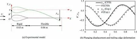
Fig. 3 Code validation with experimental results of Heathcote and Gursul.27
3. Results and discussion
3.1. Periodical and non-periodical aerodynamic forces in typical cases
According to previous studies8,10on the transient forces of rigid airfoil,Reandh0* are found the two key parameters influencing the aerodynamic periodicity in terms of a short plunging period (i.e. 10 plunging periods). Following the previous studies,8,10the aerodynamic periodicity of flexible airfoils is further explored firstly based on the typical cases atJ=0.5, α0=20° and ρ* = 103. Three airfoils, that is rigid(i.e. Π = ∞), flexible (i.e. Π=4.5) and very flexible (i.e.Π=0.45) airfoils, are considered. Their transient aerodynamic forces under differentReandh0* are computed and then those cases are further divided into periodical(rms<0.01) or non-periodical (rms>0.01) based on the criterion of rms.
Fig.4 shows that aerodynamic periodicity of flexible airfoil is qualitatively similar to that of rigid airfoil. Periodical and non-periodical cases also exist for both flexible and very flexible airfoils,and the regime can still be divided into three zones(i.e. zones I, II, and III). Zones I and III only contain periodical and non-periodical cases, respectively, and zone II is a transition zone containing periodical and non-periodical cases.Furthermore, with the increase inh0* but fixedRe, aerodynamic forces(i.e.,CLandCD)gradually transit from periodical(i.e.zone I)to non-periodical(i.e.zone III)regardless of airfoil flexibility.In previous study,10two iso-lines of plunging amplitudeRenumberReh0(defined as 4h02f/ν), are introduced to describe the boundaries between zones I - III of rigid airfoil.Following this approach, we still use this criterion to divide the three zones. Please note that in our previous study on the aerodynamic periodicity of rigid plunging airfoil, it was revealed that when rigid airfoil is in hovering or moves in a fast velocity (e.g.J=1), the aerodynamic force may be periodical for highh0*cases(h0*>0.4)even though their Re are greater than the predicted values obtained by the criterion in lowh0*.As similar phenomenon is also seen in flexible airfoils,we draw these two boundaries based on the cases withh0* < 0.4. All the cases below the lower boundary are all periodical while all the cases above the upper boundary ath0* < 0.4 are all non-periodical.
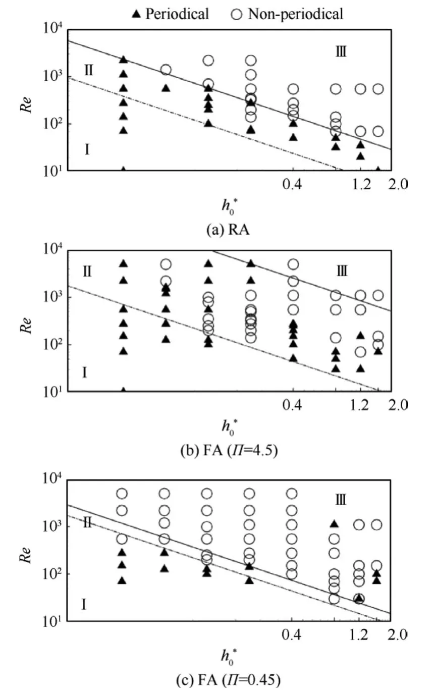
Fig. 4 Aerodynamic periodicity given different Π values with J=0.5.
As wing flexibility enhances, significant changes in aerodynamic periodicity can be observed.As the airfoil becomes flexible, i.e. Π decreases from ∞∞to 4.5, the upper boundary significantly moves upward while the lower boundary slightly moves upward. Although, compared with the aerodynamic periodicity of Rigid Airfoil (RA) and Flexible Airfoil (FA)(Π=4.5)in Fig.4,more non-periodic state points are appearing in region Ⅱas region II is enlarged. In reality, an enlarged region II is mainly generated due to the upward moving of the upper boundary and caused by much more non-periodical cases for rigid airfoil becoming periodical as airfoil is of medium flexibility. So it is indicated that medium flexibility enhances aerodynamic periodicity in typical cases. However,as airfoil flexibility continues to increase (e.g. Π decreases to 0.45),except for a few points ath0*>0.4 where aerodynamic periodicity changes from non-periodical to periodical, the upper boundary withh0*<0.4 greatly drops.It is further suggested that very flexibility only worsen the aerodynamic periodicity.
3.2. Effect of h0* and Re on aerodynamic periodicity

For flexible airfoil plunging at fixed angle of attack, the added-mass forceCamis caused by the linear acceleration of plunging motion as well as the passive pitching motion.Camcan be approximately computed as
To address the periodicity of circulation force,vortex fields in the 35th plunging period for these threeh0* cases are also plotted in Fig. 5. The flow structure is much complicated at mediumh0*= 0.2 than that ath0*= 0.025 and 1.6 as shown in Fig. 5(b). Ath0* = 0.2, the anti-clockwise and clockwise LEVs successively form in upstroke and downstroke.A vortex dipole is then formed and shed from airfoil at the middle of downstroke. The vortex dipole first migrates forward with the action of reduced flow due to airfoil plunging and after a chord length migration distance, it converts downstream. A concentrated strong TEV is observed to be generated above airfoil upper surface near the TE.As TE deforms in the opposite direction as airfoil plunging, only low intensity TEV is generated and develops slowly. Afterwards, these TEVs gradually merge into the concentrated vortex.This concentrated vortex occupies a large zone above airfoil upper surface,leading to a slow pressure area as well as suction acting on airfoil.The concentrated vortex is unstable and its location,scale and shape vary significantly.At the middle of the downstroke in subsequent plunging periods(Fig.6(a)),this vortex even approaches the LE and merges with LEV. Thus, there are severe airfoil-vortex and TEV-LEV interactions in this case.The changes in vortex structure definitely result in aerodynamic non-periodicity.
Finally,the cases at the sameRe=550 but differenth0*=0.025 and 1.6 are analyzed.At a smallh0*=0.025(Fig.5(a)),both LEV and TEV of flexible airfoil undergo a slow formation and development process in a plunging period and both of them evolve in a finite space due to a high plunging frequency. A series of LEVs merge with the previous formed low-intensity LEVs and a large,nearly stationary vortex is generated near the LE after the formation rate and dissipation rate of LEV balances with each other. Besides, only a weak shear layer is found attached to the airfoil surface near the TE. As the vortex is nearly stationary in a complete plunging period,periodical aerodynamic forces are produced. Compared to the cases ofh0*=0.025 and 0.2, a larger plunging magnitude ath0*=1.6 guarantees airfoil a long distance for its LEV and TEV to fully develop (see Fig. 5(c)). In this case, LEV and TEV are of high intensity and the vortex cores are far from airfoil surface but close to each other. Besides, LEV and TEV approximately develop in the vertical direction, i.e. the plunging direction.Therefore,both the LEV-TEV and airfoil-vortex interactions might be enhanced. As a result, the vortex structure in different plunging periods varies (Fig. 6(b)), directly causing non-periodical aerodynamic forces production.
The increase inReweakens the effect of viscosity and decreases vortex dissipation, and thereby it may be harmful for periodical aerodynamic forces generation. Fluid structures around flexible airfoils taken from cases where theRevalues are 50, 550, and 2200 buth0* = 0.4 are further analyzed to determine the effect ofRe. Aerodynamic forces produced by the case withRe=50 are periodical (rms=0.0023) while those by the other two cases are non-periodical based on the criterion of rms (rms=0.0300 and 0.0508 atRe=550 and 2200, respectively). Their vortex fields at the middle of the downstroke obtained from four successive plunging periods are plotted in Fig.7.Fig.7 shows that,at the sameh0*,similar vortex fields of flexible airfoils are observed atRe<550. At lowRe=50, there is a strong vortex dissipation effect on the flow and thus the vortex generation and dissipation can maintain a balance.As a result,periodical aerodynamic forces are produced. AsReincreases to 550,the vortex dissipation is weakened and the balance is broken.Consequently,stable vortex structure cannot be kept and non-periodical aerodynamic forces are produced.With the increment ofRe,vortex dissipation becomes weaker than vortex generation. Besides, due to the effect of airfoil TE deformation,the vortex structure is also significantly changed. A complicated flow pattern is observed,especially in the zone near TE,causing non-periodical aerodynamic forces production.As a much weak effect of vortex dissipation atRe=2200, a periodical shedding vortex pair is generated instead of the concentrated vortex found atRe<550. This vortex pair sheds from airfoil TE; therefore there are no severe airfoil-TEV and LEV-TEV interactions.Consequently, the flow structure is stable and aerodynamic forces become periodical.
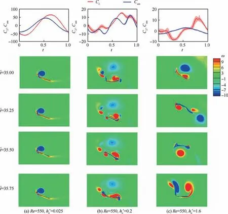
Fig. 5 Mean value and standard deviation of CL,Cam in the 30th - 40th plunging periods, and vorticity contours in the 35th plunging period produced by flexible airfoil with Π=4.5 at Re=550 but different h0* values.

Fig. 6 Vorticity contours of flexible airfoil at the middle of downstroke for subsequent plunging periods in cases of Re=550 and J=0.5 but different h0*.
3.3. Effect of flexibility on aerodynamic periodicity
3.3.1. Aerodynamic difference between rigid and flexible airfoils
Compared to rigid airfoil, aerodynamic periodicity is greatly enhanced by medium flexibility but deteriorated as airfoil becomes very flexible. To address the reason for this phenomenon, we concentrate our interests in the difference of aerodynamic forces and vortex structure between rigid,flexible and very flexible airfoils. Firstly, we address the difference on aerodynamics between rigid airfoil and flexible airfoil by reconsidering the cases withh0* = 0.025, 0.2 and 1.6 butRe=550 (Fig. 8). The three cases are of the same periodicity between rigid and flexible airfoils.
We presented the averaged and standard deviation ofCLandCDamong the 30th - 40th periods in Fig. 8. The Power Spectral Densities (PSDs) of the time courses ofCLandCDvia Fourier analysis. As can be seen from Fig. 8, the aerodynamic forces produced by rigid airfoil and flexible airfoil have the same periodicity but distinct differences in flow patterns.At= 0.2, the power spectrum contains the fundamental oscillating frequencyfn/f=1 and its harmonic frequenciesfn/f=2,fn/f=3 andfn/f=4. Thus, the time course ofCLandCDin this case is non-periodical. At= 0.2, obvious differences in vortex structure, especially in TEVs, are observed between rigid airfoil and flexible airfoil. For flexible airfoil, a concentrated vortex accumulated by TEVs is the distinguished feather of vortex structure near TE. However, when airfoil becomes rigid, a downward migrating vortex street is formed instead.This is mainly because a series of high-intensity TEVs are generated without airfoil deformation. Despite similar LEV structure, the vortex street near the LE of rigid airfoil is of high intensity and therefore its upstream migration distance before altering its migration direction is much farther than that of flexible airfoil.Although the flow pattern changes,significant interaction between LEV and TEV is also clearly found in rigid airfoil. For example, as rigid airfoil plunges downward (e.g. ^t=35.75), the TEV formed in previous upstroke is driven to migrate forward by the induced velocity with the formation of new TEV; then, the forward migrating TEV merges into the LEVs. The interaction between LEV and TEV enhances the complexity of fluid structure and thus enhances the aerodynamic non-periodicity. Therefore, though the aerodynamic forces of rigid and flexible airfoils are both non-periodical, the transient aerodynamic forces and flow structure evolutions are very different.

Fig. 7 Vorticity contours of flexible airfoils at the middle of downstroke for subsequent plunging periods in the case of h0* = 0.4,J=0.5 but different Re.
When rigid airfoil and flexible airfoil plunge at smallh0*=0.025, there is only fundamental oscillating frequencyfn/f=1 seen in the power spectrum ofCLandCD, corresponding to a periodical case. Weak LEV and TEV are both observed and they slowly accumulate due to a fast plunging frequency and small plunging amplitude. The accumulating and dissipation rate of LEV and TEV of two airfoils can be balanced,making their aerodynamic forces periodical. Differently,LEV and TEV structures of rigid airfoil are significantly more complex than flexible airfoil. As airfoil plunges, the highintensity LEVs of rigid airfoil are shed from airfoil in the form of vortex pair rather than accumulating near airfoil LE as flexible airfoil. Without airfoil deformation, vortex street is alternately generated, sheds from TE of rigid airfoil and finally forms two vortex ropes.Differently,there are only weak shear layers attached to TE for the flexible wing.Whenh0*increases to 1.6, the flow structure of rigid airfoil is similar to that of flexible airfoil,which indicates that the role of airfoil deformation on aerodynamic periodicity at highh0*is not as important as that at the medium and lowh0*.
In summary, despite the same aerodynamic periodicity at the sameh0*,the vortex structures and flow patterns have been significantly changed due to airfoil deformation.The intensityreduced LEV and TEV of flexible airfoil due to airfoil deformation mainly account for the difference in flow patterns.
3.3.2. Changes in aerodynamic periodicity due to airfoil flexibility
As can be clearly seen from Fig. 4, aerodynamic periodicity improvement caused by medium flexibility mainly occurs in those cases with moderateh0* and highRe. Hence, we choose the cases withRe=2200 andh0* = 0.2 for analysis. In this case, the maximum rms of aerodynamic forces, includingCLandCD, decreases from 0.0300 (i.e. non-periodical) for rigid airfoil to 0.0032 (i.e. periodical) for flexible airfoil.
Fig. 9 presents the transient aerodynamic forces and the vertical displacement of airfoil trailing edge in the inertia system. It can be clearly found that the peak values ofCLandCDproduced by rigid airfoil in ten plunging periods both fluctuate and the fluctuation ofCLis almost 15% of the peak value.In contrast,the peak values ofCLandCDof flexible airfoil are kept the same values. Besides, the transient forces of flexible airfoil decrease compared to that of rigid airfoil,especially in upstroke. It is suggested that airfoil aerodynamic load is reduced with airfoil deformation. As shown in Fig. 9(b), the vertical motion of the TE of the flexible wing lags behind the active plunging motion by about 80°. In upstroke(e.g.=44.0-44.5), the flexible wing’s TE first moves downwards and then changes its direction. In the middle upstroke,both the plunging velocity and trailing edge displacement reach their peak values. At this time, the absolute velocity of airfoil TE approaches zero and the plunging effect is greatly weakened due to airfoil deformation, which accounts for the phenomenon of aerodynamic uploading. A weak plunging effect is also reflected in vortex evolution. Fig. 9(c) and 9(d)present vorticity contours of flexible and rigid airfoils for subsequent four plunging periods. The vortex structure of rigid airfoil atRe=2200 andh0* = 0.2 is similar to that atRe=550 andh0* = 0.2 while that of flexible airfoil is somewhat different. In the case ofRe=2200 andh0* = 0.2, TEV of flexible airfoil formed is no longer accumulated near TE due to weak dissipation effect at highReand it migrates downstream instead. As the intensity of TEV is greatly reduced,TEV completely sheds from TE and it does not interact with LEV.Therefore,a stationary vortex structure of flexible airfoil as well as periodical aerodynamics is generated atRe=2200 andh0* = 0.2.
Attentions are then concentrated on the question why aerodynamic becomes much more non-periodical when airfoil becomes very flexible.The changes in aerodynamic periodicity mainly focused in those cases at small and mediumh0*,i.e.h0*< 0.4 (Fig. 4). Thus, we choose the cases atRe=275, 550,and 2200 but the sameh0*=0.2 for analysis due to their severe aerodynamic non-periodicity.Fig.10 plots the mean values and standard deviation of transient aerodynamic forces averaged between the 30th and 40th plunging periods. AsReincreases from 275 to 2200 ath0*=0.2,the standard deviation of transient forces greatly increases, i.e. the aerodynamic nonperiodicity is enhanced. PSD analysis is also conducted. It shows that atRe=275, PSD is concentrated at several frequencies which is times of plunging frequency while the PSD is dispersed along a wide frequency at highRe. As airfoil becomes very flexible, a sever deformation is also produced and a similar complex deformation is also found from our previous investigation.19With the action of non-periodical aerodynamic forces, non-periodical deformation is also generated, which in turn deteriorates the aerodynamic periodicity.

Fig. 8 Mean values and standard deviation of transient aerodynamic forces in the 30th-40th plunging periods as well as vorticity contours in the 35th plunging period produced by flexible and rigid airfoils in the case of Re=550 but different h0*.
3.4. Effect of J
To determine the effect of variableJon aerodynamic periodicity,the periodicity of numerous cases with differentReandh0*values are finally analyzed atJ=0 andJ=1.0. As the aerodynamic periodicity of plunging airfoil can be greatly enhanced by medium flexibility, e.g.Π=4.5; therefore a flexible airfoil case with Π=4.5 is chosen as a typical case in this part. The boundaries under the criterion rms ≤0.01 with differentJvalues are illustrated in Fig. 11. The aerodynamic periodicity of flexible airfoil at differentJvalues is qualitatively the same as that of rigid airfoil and the flow regime can still be divided into periodical, transitional, and nonperiodical regions atJ=0 andJ=1.0. AtJ=0 andJ=1.0, periodical cases of flexible airfoil withh0* > 0.4 can be observed above the extended upper boundary of the transitional region withh0* ≤0.4 while periodical cases withh0* > 0.4 atJ=0.5 can be observed under the extended upper boundary whenh0* ≤0.4. A larger transitional area due to significant upward of upper boundary atJ=0.5 is obtained compared to cases atJ=0 andJ=1.0.

Fig. 9 Transient aerodynamic forces, trailing edge deformation displacement as well as vorticity contours of flexible and rigid airfoils at the middle of downstroke for successive plunging periods in the case of Re=2200 and h0* = 0.2.
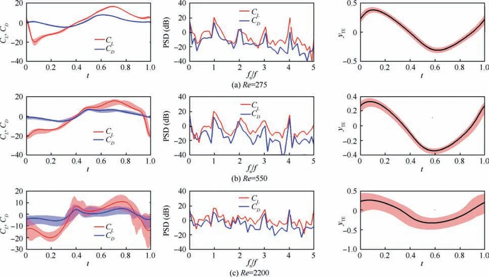
Fig.10 Mean values and standard deviation of transient aerodynamic forces as well as trailing edge deformation displacement at h0*=0.2 but different Re.
The reasons why the transitional area atJ=0.5 is larger than that atJ=0 andJ=1.0 are discussed based on the case atRe=2200 andh0*=0.2,of which the aerodynamic forces are periodical atJ=0.5 but non-periodical atJ=0 andJ=1.0. Fig. 12 shows the vortex contours at the middle of the downstroke of three successive plunging periods forJ=0, 0.5, and 1.0. WhenJ=0, the formation and development of fluid field are contributed by airfoil plunging motion and influenced by airfoil deformation as no incoming free stream exists. Although most of the previously formed LEVs and TEVs migrate forward and backward,respectively, a proportion of the LEVs and TEVs remain around the airfoil and interact with the newly formed vortices.The strong interaction between these vortices leads to various vortex structures at different plunging periods, thereby resulting in non-periodical aerodynamic forces. AtJ=1.0, LEVs and TEVs move backward directly after forming because of the fast incoming free stream.However,the fast incoming free stream also messes up the backward-moving LEVs and TEVs and causes the locations and intensities of these vortices to vary in different periods. Therefore, aerodynamic force atJ=1.0 is nonperiodical. Comparatively, the influence of incoming free stream atJ=0.5 on vortex evolution is not as significant as that atJ=1.0 but is greater than that atJ=0. Fig. 12(b)shows that the medium incoming flow induces the previously formed LEVs to move backward after undergoing a short forward migration,carries the TEVs to the rear,and ensures that the TEVs migrate regularly. Consequently, the complex vortex-vortex and vortex-airfoil interactions occurring atJ=0 are avoided. Moreover, when the incoming flow is low, the migration of vortices can still be regular. The two factors are beneficial for the formation of a periodical vortex field,thereby contributing to the aerodynamic periodicity atJ=0.5.

Fig. 11 Aerodynamic periodicity of flexible airfoil given different J values.
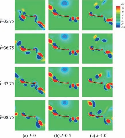
Fig. 12 Vorticity contours of flexible airfoils at the middle of downstroke in three successive plunging cycles given Re=2200,h0* = 0.2.
4. Conclusions
(1) Qualitatively, the aerodynamic periodicity of flexible and very flexible airfoil varying withReandh0* is consistent with that of rigid airfoil. With the increase inReandh0*, aerodynamic forces produced are transformed from periodical to non-periodical.Both rapid vortex dissipation at lowReand high contribution of added mass force to aerodynamic forces at lowh0* still account for the periodical aerodynamic forces production of flexible airfoil.
(2) Compared to rigid airfoil, aerodynamic periodicity is greatly enhanced by applying medium flexibility. This finding can be attributed to the passive deformation of flexible airfoil. This is because trailing edge deformation reduces the effect of airfoil plunging on the fluid field around the airfoil to some extent, and therefore strength and structure of LEV and TEV are significantly changed and vortex-vortex and vortex-airfoil interactions greatly weakened. As airfoil becomes very flexible, aerodynamic periodicity is greatly deteriorated,especially in those cases of small and mediumh0*, i.e.h0* < 0.4.
(3) Aerodynamic periodicity is initially improved asJincreases to a medium non-zero value and is then weakened asJcontinuously increases. At mediumJvalue,previously formed LEVs and TEVs during airfoil plunging move away from the airfoil and periodically shed.Consequently, non-periodical cases with low and high values ofJtransform to periodical cases.
(4) In summary, flexibility can, to some extent, improve the aerodynamic periodicity of a plunging airfoil.Moreover, flexibility can significantly decrease the amplitude and fluctuation of transient aerodynamic forces in a plunging period, which may be also beneficial for the flight control design of flapping micro-air vehicle.
Declaration of Competing Interest
The authors declare that they have no known competing financial interests or personal relationships that could have appeared to influence the work reported in this paper.
Acknowledgements
This study was co-supported by the National Natural Science Foundation of China (Nos. 11902017 and 11672022) and the China Postdoctoral Science Foundation (No. 2019M650418).
杂志排行

CHINESE JOURNAL OF AERONAUTICS的其它文章
- Tangling and instability effect analysis of initial in-plane/out-of-plane angles on electrodynamic tether deployment under gravity gradient
- Effects of swirl brake axial arrangement on the leakage performance and rotor stability of labyrinth seals
- Experimental and computational investigation of hybrid formation flight for aerodynamic gain at transonic speed
- Tomography-like flow visualization of a hypersonic inward-turning inlet
- Hypersonic reentry trajectory planning by using hybrid fractional-order particle swarm optimization and gravitational search algorithm
- A theoretical and 1-D numerical investigation on a valve/valveless air-breathing pulse detonation engine