Dynamic analysis of the composite laminated repaired perforated plates by using multi-patch IGA method
2021-03-16JamshidFAZILATIVahidKHALAFI
Jamshid FAZILATI, Vahid KHALAFI
a Aeronautical Science and Technology Department, Aerospace Research Institute, Tehran 14657-74111, Iran
b Aerospace Engineering Department, Shahid Sattari Aeronautical University of Science and Technology, Tehran, Iran
KEYWORDS Composite laminate;Perforated plate;Bonded repair;Isogeometric analysis (IGA);Multi-patch model
Abstract The bonded repair techniques seem to be the most frequent procedures in the aviation maintenance. The achieved composite repaired perforated thin-walled plate is a complex geometry with high numerical analysis cost.The NURBS-based Isogeometric Analysis(IGA)proposes a sensible and affordable tool to carry out such geometry analysis. In this context, a well-known technique is to divide the original geometry assembly into number of simple neighbors connected geometries. In the present study the free vibration analysis of the perforated plates repaired on one side with an external bonded composite laminated patch is investigated. A multi-patch geometry modeling approach is implemented in line with the first order shear deformation theory of plates. In order to hold the geometry integrity and uniformity, all the degrees of freedom between adjacent geometry patches are completely tied through implementing a Nitsche method. To show the effectiveness and accuracy of the developed formulation, some representative results are extracted and compared with those from literature. The effects of geometrical as well as material parameters including boundary condition,cutout shape,and repair layup on the dynamic response of the repaired perforated plates are then investigated.
1. Introduction
The Structural elements especially in case of aeronautical vehicles are at the risk of being damaged during operations. A common solution to these cases is to remove the damage area or material by cutting out procedures and then to do a subsequent fix using proper repair patches on the cutout area. A most practical and easy to apply repair approach is the adhesively bonded external patches which eliminates the riveting procedures. The use of the adhesively bonded composite patches as a repair approach has many advantages compared to the conventional mechanically fastened repair ones.1Unlike bonded ones, the repaired structural elements containing riveted, bolted or welded joints are subjected to important stress concentrations as well as distortion of material properties.Regarding to their special characteristics including corrosion resistance, ease of application, providing high strength to weight ratios and relatively low costs, the composite repair patches are the widespread and preferred decisions. Using the advanced tow steered variable stiffness composite laminates can further improve the performance and life span of the repaired elements. Accordingly, it is of great importance that the mechanical characteristics of the resulting repaired geometry must be reconsidered and evaluated.
Baker and Jones2summarized the most of the work done on the development of the adhesively bonded repair before 1988. Chue and Liu3studied the elastic stress state on the bonded composite patches for a plate with an inclined central through crack under biaxial loading by using threedimensional finite element method.Pai et al.4investigated static strength and dynamic response of the cracked aluminum plates repaired with composite laminated patch using twodimensional finite element method. Wang and Pidaparti5presented experimental results and analytical predictions based on Rose’s analytical solution and Paris’ power law to investigate the static and fatigue response of the cracked aluminum specimens with and without bonded composite patches.Naboulsi and Mall6analyzed the repair of a cracked metallic structure with laminated composite patch using a three-layer two-dimensional finite element model.Engels and Becker7presented closed-form solution for the laminated plate with an elliptical cutout which externally repaired by elliptical composite laminated patch. Guo8numerically and experimentally investigated the buckling behavior of perforated composite laminated plate with reinforced cutouts including bonded metal and composite patches. Rezaeepazhand and Sabouri9,10studied the free vibration and buckling behavior of the perforated metallic plates with single-sided and double-sided composite laminate patch repairs.
The Isogeometric Analysis(IGA)has been originally implemented by Hughes et al.11.The IGA was aimed to make a shortest connection between the initial geometry by the Computer Aided Design(CAD)and the numerical Finite Element Analysis(FEA)model.The main idea of IGA is to adapt the basis functions of the CAD geometry approximation (i.e. the NURBS functions)to elemental shape functions of the FEA.These basis functions simultaneously fitted to field variables approximation as well as to the geometry representation.As a result,the IGA approach can guaranty the exact geometry modeling even at the coarse discretization level and therefore may reduce the computational costs while maintaining the accuracy level.
Shojaee et al.12investigated the free vibration and buckling analysis of the classical isotropic and composite laminated thin flat plates using NURBS-based isogeometric analysis method.Valizadeh et al.13analyzed static, free vibration, buckling and flutter behavior of functionally graded plates based on the Reissner-Mindlin theory by using IGA. Nguyen et al.14developed a Nitsche method to couple non-conforming two and three dimensional NURBS patches in the context of IGA.Dornisch et al.15developed a mortar-type method for coupling of non-conforming patchs in NURBS-based isogeometric analysis. Du et al.16studied the free vibration of Reissner-Mindlin plates using IGA while Nitsche method was implemented to encompass non-conforming multi-patches in the numerical model. Yu et al.17presented isogeometric formulation based on First-order Shear deformation plate Theory(FST) and performed the free vibration and buckling analysis of composite laminated plates.Zhang and Wang18proposed a meshfree formulation for the B-spline and Non-Uniform Rational B-Spline (NURBS) basis functions in isogeometric analysis. They showed that after properly introducing meshfree nodes,support size and consistency conditions,the reproducing kernel meshfree shape functions are capable of exactly representing the isogeometric B-spline and NURBS basis functions.Zhang et al.19presented an isogeometric analysis discontinuous Galerkin method to solve problems on the union of the overlapped patches.Xue et al.20investigated the free vibration of functionally graded plates considering in-plane material inhomogeneity by using NURBS-based IGA in conjunction with a refined plate theory. The analysis of skew and elliptical plates was performed and the effects of the geometry plan,boundary condition and material inhomogeneity on its dynamic characteristics were discussed. Gu et al.21developed a multi-patch isogeometric formulation where the Nitsche method was applied to connect adjacent model patches. In their study,the locally refined B-splines was used and an adaptive scheme for two-dimensional elasticity problems was proposed. Hao et al.22,23performed buckling analysis and layup optimization of the variable-stiffness laminated plates containing circular cutouts by using an isogeometric formulation based on the Reissner-Mindlin plate theory. The Level Set Method (LSM) technique was utilized to analyze the effects of multiple or free-shape cutouts using a single-patch approach. Do and Lee24analyzed the free vibration of functionally graded plates with complex cutout shape by using a higher order IGA method. Pham et al.25implemented a coupled FEM-BIEM technique to analyze 3D cracked components repaired by adhesively bonded patches. Devarajan and Kapania26presented a NURBS based isogeometric FEA to analyze the thermal buckling of stiffened laminated composite plates with cutouts.
Recently, the authors of the present manuscript, investigated the supersonic panel flutter as well as dynamic parametric instability of tow-steered variable stiffness composite laminated quadrilateral plates using a developed NURBS IGA formulation based on FST.27,28The free vibration analysis of VSCL plate containing embedded perforations of various layouts and positions was also reported using the FST-IGA formulation with implemented Nitsche technique.29
In the present paper, the free vibration analysis of the perforated plates with repair patch is performed. A one-sided bonded composite laminated repair patch is assumed.In order to analyze the aforementioned geometry, a multi-patch geometry modeling approach is utilized.In this approach the geometry is divided to number of adjacent planar IGA elemental patches which are completely interconnected by applying the Nitsche method. A NURBS based IGA formulation is developed and a Nitsche technique which satisfies full coupling of the degrees of freedom of the adjacent conforming IGA geometrical patches is implemented in the context of the first order shear deformation theory. In order to show the quality of the developed formulation some representative problems are provided and some investigations on the structure behavior are addressed.
2. Computation scheme
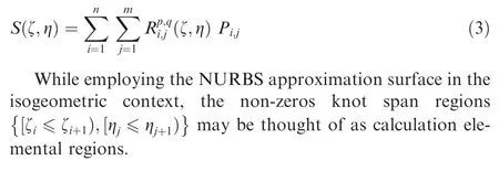
In the context of IGA method,the NURBS basis functions are utilized as the geometry as well as displacement field approximation functions. The bivariate NURBS basis approximation function corresponding to a NURBS surfacecould be defined by using the weighted average of number of (nandmbase functions in two main orthogonal directions of ζ and η) B-spline basis functions of the same order as follows29:

wherepandqare the orders of the constructive B-spline functions,Ni,pandMj,q, in two orthogonal directions andwi,jare the weight coefficients.

The NURBS approximation bidirectional function is defined using a set of knot vectors,[ζ1=0,... ζi..., ζn+p+1=1],[η1=0,... ηj..., ηm+q+1=1], along with a set of control points coordination(Pi,j{i=1,..,n,j=1,..,m}).The NURBS surface,S,of orderpin ζ direction and orderqin η direction is defined as:
2.1. Single-patch free vibration formulation
Based on the first order shear deformation plate theory, the displacement of an arbitrary point on the plate,, may be approximated as:

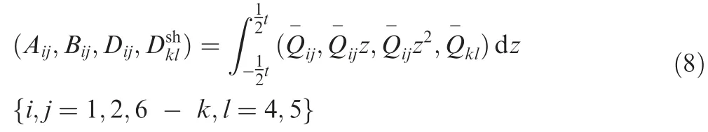
whereu0,v0andw0are displacements of the corresponding point on the plate reference surface. βxandβyare the midplane rotations about coordination axis.The linear strain vector is defined as,

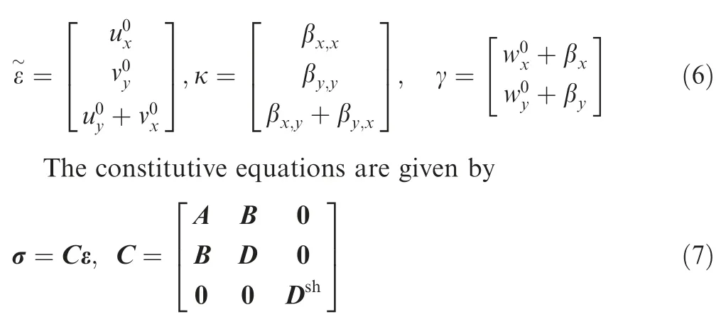
Here, A, B, D and Dshare the general matrices of extensional, bending-extensional coupling, bending, and transverse shearing stiffnesses, respectively and are calculated through integration over plate thickness,t, as,
By considering the NURBS basis functions as function approximations, the displacement field on the geometrical patch, u0, is interpolated as,

wherencpdenotes the total number of control points corresponding to the geometrical element. The expression may be organized in a matrix form as,

By the substitution of Eq.(11)into Eq.(5)and(7),the following relationships are obtained,

The solution of the free vibration problem is sought through the principle of virtual work. The total energy in the geometry is determined by its kinetic (T) and internal strain(U) energy components,

The total internal elastic strain energy and the total kinetic energy of the laminated geometry while taking into account the effects of inplane as well as rotational inertia effects,could be approximated after some simplifications as,

By substituting the strain and stress vectors of Eq.(12)into the Eq.(14),followed by minimization of the total energy term with respect to the vector of degrees of freedom and assembling the elemental matrices throughout the whole geometry of a single patch, the governing equation of the free vibration problem is obtained and expressed in standard matrix form as,

where
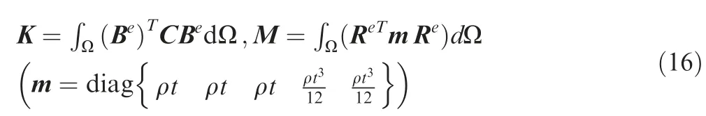
The obtained equation dominates the free vibration problem of a single IGA geometrical element which may be treated by using a standard Eigenvalue procedure.
2.2. multi-patch geometry modeling approach
An analysis on a flat plate containing an embedded cutout may be carried out through using a multi-patch geometrical approach. In this context, a series of adjacent nonoverlapping sub-geometries (i.e. patches) are interconnected through their shared boundaries to form the perforated geometry.Fig.1 typically depicts a geometry which is structured by using two geometry sub-domains Ω1and Ω2.The sub-domains(each sub-domain denotes a NURBS patch) have ties along their meeting edges.
Since the problem governing Eq. (15) is just valid within a single patch, some interface equations must be also applied in order to take into consideration of the whole integrated body while maintaining the continuity and unity of the model. The Nitsche method is applied to implement ties between adjacent patch geometries. The governing equations along with the boundary and initial conditions are presented in Eq. (17a-d).The conforming equations on the shared boundary are expressed as in Eq. (17d).


Fig.1 Perforated panel multi-patch computational domain with internal interfaces between patches and boundary conditions.
In the absence of acting of either external tractions or volume forces, the Nitsche method looks for the displacement unknownssuch that the following equality is established between patches [16],

whereware the trial functions those are set to zero onSu*and α is a free parameter for Nitsche method. A similar relationship may be released for other probable adjacent patch pairs.The outward shared boundary normal matrix, n, taking into account the in-plane as well as out of plane displacement degrees of freedom, is arranged as,

wherenx,nyandnzare the components of the outward unit normal boundary vectors in three main directions. The resulting governing equation of free vibration for the whole body consisted of multi-patch geometry and by implementing of the Nitsche method is expressed as,

In this equation, (q1,...,qN) are the exact displacement functions ofNgeometry patches. The multi-patch mass matrix,are defined as,

here Kbdenotes the bulk stiffness matrix; Knand Ksare the interfacial stiffness matrices or the multi-patch coupling matrices and are introduced as,

Assuming a simple time harmonic motion with introducing unknown coefficients Q and ω(i.e.the natural frequency of the geometry), the global vector of displacement function is approximated as,

Substituting Eq. (23) into Eq. (20) gives the eigenvalue equation of the free vibration of the multi-patch geometry as,

The natural frequencies along with their corresponding mode shapes may be extracted by applying a standard eigenvalue procedure.
2.3. Generalized multi-patch modeling for repaired perforated plate
The multi-patch isogeometric formulation is adopted to the free vibration problem of perforated plate with repair patch.In this regard, the following assumptions are made,
●A single one-sided patch repair plate of arbitrary shape is applied.
●The repair patch is completely bonded to the perforated plate by using an isotropic adhesive layer.
●Ideal ties are assumed between the perforated base plate,adhesive layer and repair patch laminate.
●Any probable mechanical contact is overlooked.
●A global coordination system is located on the mid-surface of the base plate.
●The whole geometry is modeled as a multi-patched single laminate.
A typical rectangular repaired perforated plate geometry is illustrated in details in Fig. 2. The origin of the coordination axis is located at the center of the mid-surface of the base plate andWs,Wp,Ls,Lpandcare the width of the base plate,width of the repair patch, the length of the base plate, the length of the repair patch and the cutout size parameter, respectively.The thickness parameters corresponding to the plate laminate,adhesive layer and laminated patch arets,taandtp.
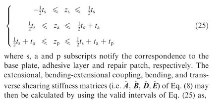
Regarding to the location where the coordination axis positioned as shown in Fig. 2, the height positions corresponding to the integration in the thickness direction on base plate,the adhesive layer, and the repair patch are according to the followingzranges,
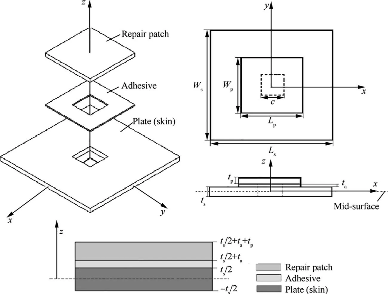
Fig. 2 Geometry details of typical rectangular perforated plate with external bonded patch repair.

The repaired perforated plate is then divided into number of geometrical sub-domains called geometrical patches. The IGA formulation is implemented through every single geometrical patch.The global multi-patch governing equations of the problem are obtained after meeting the coupling conditions at the sub-domain interfaces through applying the Nitsche method. The layout and arrangements of cutout, repair patch and the base plate mainly influence the partitioning pattern of the geometry into geometrical patches.A probable mesh structure consisted of nine sub-domain patches is shown in Fig. 3 for a typical regular geometry with rectangular base plate,cutout and repair. The geometrical patches appeared in the domain may be categorized in to three general sub-domain layup types.The First type are those located on the base plate outside the repaired area(type I:patches 1 to 4 in Fig.3).The second are those patches located on the base plate where the repair is bonded on (type II: patches 5 to 8 in Fig. 3). The layup of the patches of the second type involves all of the base plate, the adhesive layer and the composite repair. The third are those patches located inside the perforated region which includes the composite repair layers only (type III: patch 9 in Fig. 3).
The stiffness and mass sub-matrices corresponding to each type of IGA patch types may be extracted as follows,

For a repaired perforated plate geometry discrete to number of geometry subdomains, the governing equations of all the subdomain types are extracted by using Eq. (24). The patch-coupling constraints of Eq. (17) are also taken into account to obtain the global equations.

Fig. 3 Multi-patch modeling of a rectangular repaired perforated plate geometry.
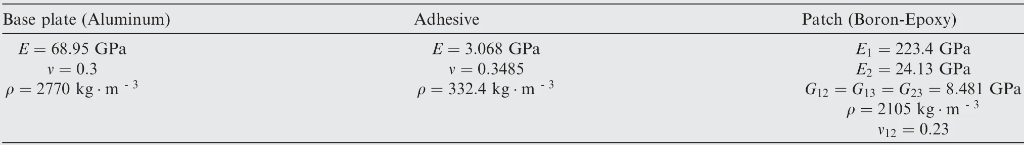
Table 1 Material properties of base plate, adhesive and composite patches.
3. Results
Some numerical case studies on the repaired perforated plates are investigated in order to show the quality of the presented IGA approach. The isogeometric results are also compared with available ones from other numerical and FEM predictions. Finite element models involving the S8R shell elements(with eight nodes with six degrees of freedom at each node)are used to model the perforated plates, adhesive layer, and repaired patches, separately. The repaired patch elements are geometrically tied to the corresponding neighbor adhesive elements and the adhesive elements are ideally tied to their corresponding patch layer elements in case of coincidence.
In all the following examples, the IGA formulation based on the cubic NURBS basis approximation functions are utilized. The integrations are numerically approximated by using of 16 Gaussian quadrature points (a 4×4 integration point array)inside the NURBS elements.Unless otherwise specified,a typical geometry with the squared base plate of length 508 mm (Ls,Ws), the base plate and repair patch thickness of 5.08 mm (ts,tp) and the adhesive layer thickness of 0.1016 mm (ta) is presumed. The material properties are given in Table 1. The patch layer is assumed from multi-ply laminated composite materials. The fiber orientations angle in every ply is measured from the modelx-direction as shown in Fig. 4.
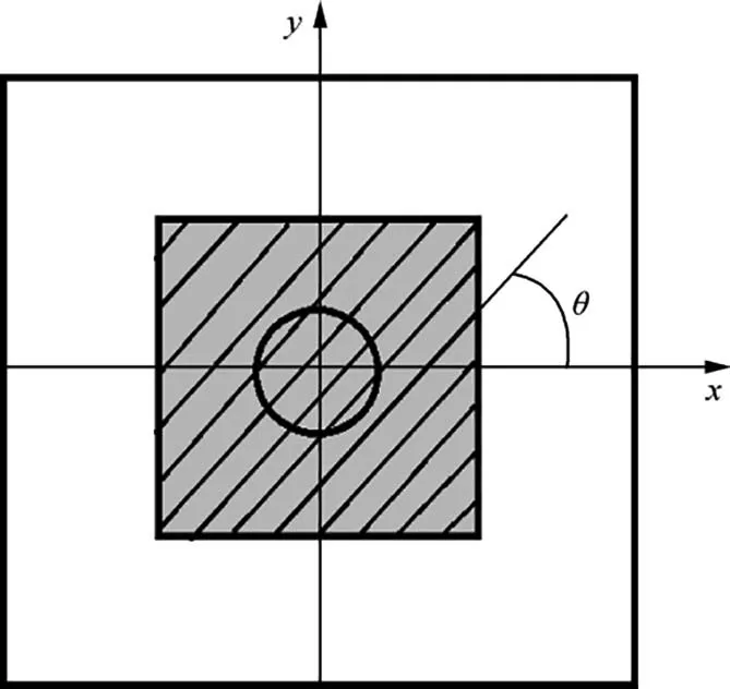
Fig. 4 Repair laminate fiber orientation angle (θ) description.

Fig. 5 Geometry, control mesh (10×10 control point per patch) and physical mesh (7×7 NURBS elements per patch) of the plate stiffened with bonded rectangular patch.
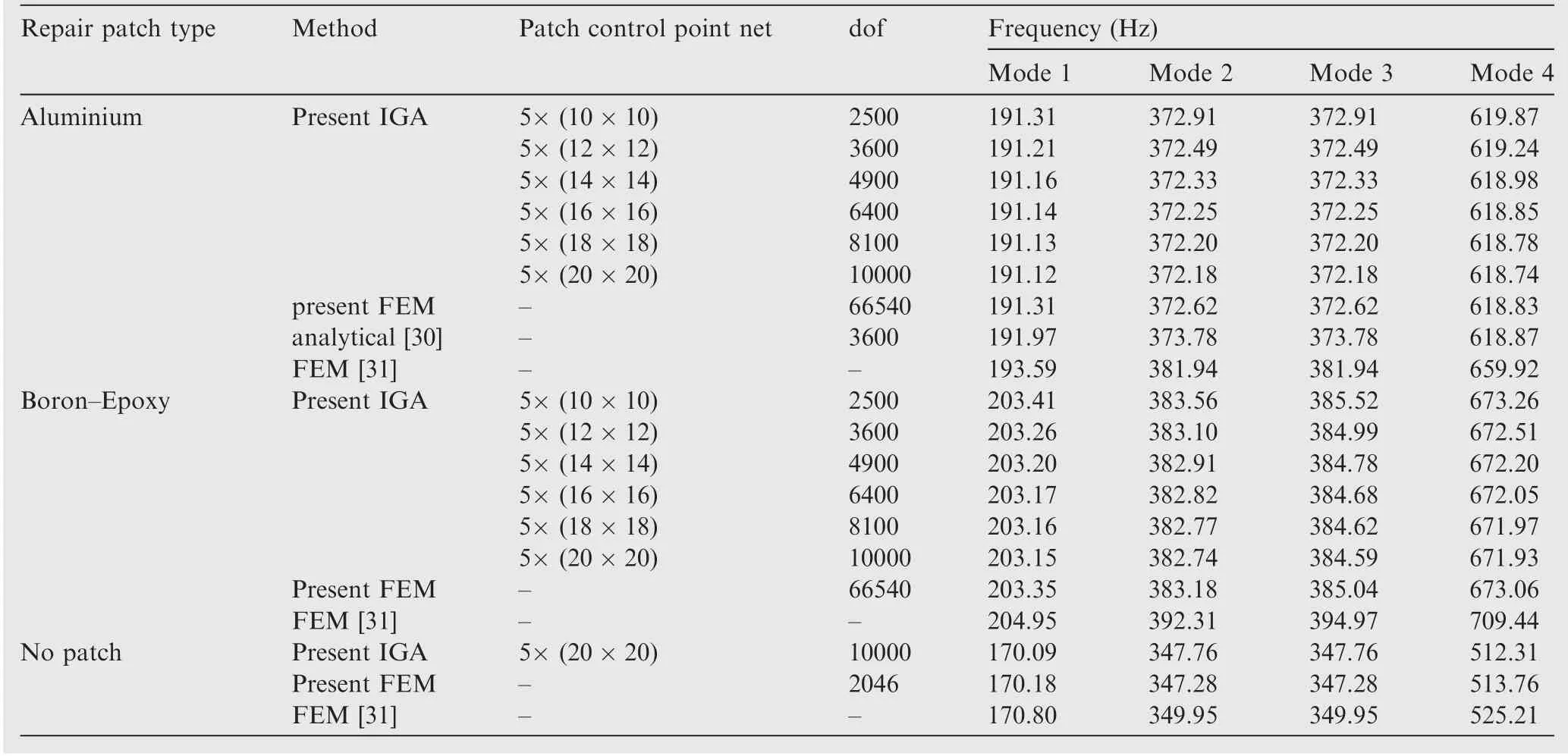
Table 2 Natural frequency of clamped square intact plate with a central patch.
A clamped (CCCC) perfect square aluminum plate with center bonded patch of the same thickness of two different patch material (e.g. Aluminum and three-layer Boron-Epoxy laminate) is considered. The natural frequencies of the plate with side patch are extracted and compared with the predictions using other theories. The geometrical characteristics of the bonded patch areLp=Wp=3Ls/7. The geometry is divided into 5 NURBS patches as shown in Fig.5.This figure also illustrates the overall geometry assembly and the IGA control mesh projected on all patches.
Table 2 presents the first four natural frequencies of the patched intact plate. The IGA results are provided for models consisting of 5 geometrical patches of different NURBS element densities.A good monotonic convergence behavior could be observed. The model with patches of 16×16 control point net(totally 6400 degrees of freedom)is found to provide sufficiently converged natural frequencies. The same predictions are provided through using the present FEM,the PVW analytical solution by Ahmad and Kapania30, and finite element method predictions by Lin and Ko31.The present FEM results are extracted by the authors using a model consisting of 3569 eight-node shell elements of S8R with a total of 66540 degrees of freedom (dof). The comparison shows a very good agreement between the predictions of the present IGA and the referenced ones.The frequencies of the unrepaired plate(without repair patch)is also provided that shows very good consistency of the IGA results with those predicted using FEM and from literature.
A square aluminum plate with square central cutout repaired with bonded four layer(θ,-θ)sBoron-Epoxy laminate is considered. The geometrical parameters are set toLp=Wp=Ls/2 andc=127 mm.The IGA numerical model is consisted of 9 NURBS geometry patches as in Fig. 6.

Fig. 7 Convergence behavior of fundamental natural frequency of 9-patch repaired perforated plate with increase in the model degrees of freedom.

Fig.6 Geometry,control mesh(9×9 control point per patch)and physical mesh(6×6 NURBS elements per patch)of the perforated plate repaired with bonded rectangular patch.

Table 3 Natural frequencies of clamped perforated plate repaired by a bonded four layer (45, -45)s laminate.
The first five natural frequencies of a clamped perforated plate with a central square cutout which is repaired using a bonded (45,-45)scomposite square laminate is extracted and the results are shown in Table 3.An IGA nine-patch geometry modeling approach is implemented and the impact of increase in the control net density in geometry patches is investigated.The problem is also solved by the authors using the FEM. A good convergency behavior could be observed. It seems that a model consisted of patches with 10×10 control nets provides the converged results.Fig.7 illustrates the faster convergence behavior of IGA calculations in case of the fundamental frequency in comparison with FEM ones extracted by the authors. The predictions of IGA are also in very good agreement with those from the finite element predictions while the number of degrees of freedom in FEM model exceeds 4.5 times that of IGA model.

Table 4 Natural frequencies of clamped perforated plate repaired by a bonded four layer (θ,-θ)s laminate.
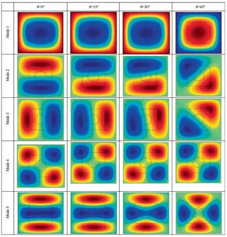
Fig. 9 Natural mode shapes of simply supported holed plate repaired by a bonded four layer laminate of layup (θ,-θ)s.
The first five natural frequencies of perforated plate repaired with a bonded laminate patch are extracted. various four layer patch angleply layups of (θ,-θ)sare considered while the base plate edges are fully constrained either simply supported or clamped. The resulting repaired panel frequencies are extracted in Table 4. Nine adjacent patches with IGA control net of 14×14 are used which totally offer a numerical model with 8820 degrees of freedom. Patch layup angles of 0 to 45 degrees are considered and the FEM predictions using a model consisting of 4352 eight node shell elements of S8R with totally 80,262 degrees of freedom are also provided. The comparison shows very good consistency between IGA and FEM predictions.
A square aluminum plate with central hole repaired with a bonded four layer(θ,-θ)sBoron-Epoxy composite laminate is considered. The geometrical properties of model are set toLp=Wp=Ls/2 andc=127 mm.In Fig.8 the NURBS control net and physical discretization of the geometry are depicted.An IGA model consisted of 9 connected constructive patches is set up with utilizing of a 9×9 array of control points (i.e. a 6×6 mesh of cubic NURBS elements) in every patch.In Table 5 the natural frequencies of the repaired holed plate are presented from IGA as well as FEM. The FEM model is consisted of 4000 eight-node shell elements of S8R with totally 74,406 degrees of freedom while the IGA model employed nine connecting patches of 14×14 control point net each with a total of 8820 degrees of freedom. Despite the significant difference in calculation costs,less than 0.5%difference may be observed which notifies the multi-patch IGA approach effectiveness. The natural mode shapes corresponding to the repaired models under consideration are shown in Fig. 9 where it shows the step-by-step variations of the mode shapes as the repair layup changes.
A clamped square aluminum plate with a complicated central cutout repaired by bonded four layer (θ,-θ)ssquare Boron-Epoxy composite laminate is considered.The geometry parameters areLp=Wp=Ls/2 anda=101.6 mm. In Fig. 10 the control points net and the physical NURBS elements of the IGA model using 15 geometry patches are presented. Each patch is approximated by using a 9×9 control points net(i.e.6×6 mesh of cubic NURBS elements).Table 6 gives the first five natural frequency of the repaired panel for repair patch layup variants where the FEM predictions of a model consisted of 1783 eight-node S8R shell elements with totally 33,900 degrees of freedom are also provided. The IGA results are obtained from a 15-patch model with employing an array of 12×12 control points over each patch(a total of 10,800 degrees of freedom).Less than 1 percent of difference could be observed between multi-patch IGA and FEM predictions in spite of one third ratio in computational effort (one third dof of IGA model regarding to FEM one).
A square aluminum plate with a central tapered straight slot repaired with bonded four layer (θ,-θ)sBoron-Epoxy composite laminate is considered. The geometric parameters are defined according to Fig.11.Four boundary condition sets of clamped (CCCC), simply supported (SSSS), CSCS and CCSS (where S and C denote simply supported and clamped edges, respectively) starting from one longitudinal edge are taken into account and the effects of different repair patch layups, boundary condition and geometrical parameters on the free vibration behavior of the geometry is investigated.
In Fig. 11 the constructing patch distribution, the control points net on the patches, the NURBS integral elements and the geometrical characteristics are depicted. The IGA computational model is consisted of 14 geometrical patches where 10×10 control points net are adopted on each one and a total number of 7000 degrees of freedom are utilized on the whole 14-patch model.Fig.11 depicts the multi-patch geometry with typical patch meshes.d1,d2andlcare end wider and tighter diameters, and length of the cutout, respectively.
The extracted natural frequencies with change in layup and boundary conditions are presented in Table 7 for the typical repaired geometry ofd1/Ls=0.20,d2/Ls=0.15,lc/Ls=0.4 andLp/Ls=Wp/Ls=0.5. The results for unrepaired intact and perforated base plates are also provided.

Fig.10 Geometry, control mesh (9×9 control point per patch) and physical mesh (6×6 NURBS elements per patch) of plate with complicated cutout repaired with square patch divided into 15 IGA patches.

Table 6 Natural frequencies of clamped aluminum plate with complicated cutout and bonded composite patch repair.
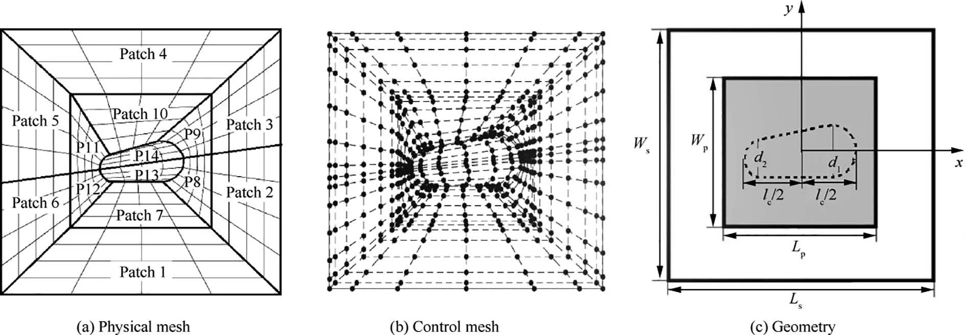
Fig.11 Geometry,control mesh(typical 7×7 control point per patch)and physical mesh(typical 4×4 NURBS elements per patch)of plate with complicated cutout repaired with square patch divided into 14 IGA patches.
The best repair stiffening (in terms of the fundamental frequency)may be obtained while using a 60(and above)degrees repair layup in CSCS edge condition which offers about 45 percent higher frequency. The minimum stiffening effect is found in CCSS boundary set model repaired using a 90 degrees patch layup which is just 16 percent. This behavior is almost reversed in case of the second and fifth natural frequencies.Except for CSCS set, the best repair layup angle is found to be 45 degrees in case of the fundamental frequency.The repair patch also majorly boosts up the first natural mode frequency of all perforated base plates except for CCSS boundary condition where the changes in the fifth frequency are more substantial.
The natural frequencies in case of clamped and simply supported constraint sets are the highest and the lowest achieved ones,respectively.From the results shown in the table,it could also be noted that in the cases of CCCC and CCSS boundary sets, the fundamental frequency of the unrepaired perforated panel is higher than that of the intact one. This means that in these cases the possibility of no repair decision may be investigated.
The variations of the repaired panel fundamental natural frequency with change in the diameters of the perforation (d1andd2), the repair layup angle (θ,-θ)sare extracted and presented in Fig. 12. Two boundary constraint sets of clamped and simply supported are considered along with the geometry characteristics oflc/Ls=0.4 andLp/Ls=Wp/Ls=0.5. The results show the increasing behavior of frequencies as the diameter ratio (d1/d2) reduces from 1.5 to 1.25. The boosting effect is more significant in case of the clamped panel, but no noticeable dependency to the repair patch layup could be mentioned in any boundary set.
The effects of change in the perforation size parameter and the repair layup is investigated on the fundamental frequency of the repaired panel. As is depicted in diagrams of Fig. 13,since the repair patch area is kept unchanged,no major impact could be found in the result of change in perforation length parameter (lc/Lp) from 0.6 to 0.8. A maximum of 6 percent of variation is observed for patch layup alternatives. Simply supported and clamped conditions on a geometry ofd1/Ls=0.15,d2/Ls=0.10 andLp/Ls=Wp/Ls=0.5.

Fig. 12 Natural frequencies of repaired plate with different central tapered straight slots and repair layups. (lc/Ls=0.4, Lp/Ls=0.5).

Fig.13 Natural frequencies of repaired plate with different central tapered straight slots and repair layups.(d1/Ls=0.15,d2/Ls=0.10,Lp/Ls=0.5).
For an unchanged perforated plate geometry,the impact of using different sizes of repair patch along with the patch layup on the resulting natural frequency of the repaired panel is studied. The repair length ratios (Lp/Ls) of 0.5,0.6, and 0.7 are assumed while the layup angle and boundary conditions are altered. The geometry parameters are set asd1/Ls=0.20,d2/Ls=0.15 andlc/Ls=0.4.Fig.14 presents the resulting fundamental frequencies where shows more notable influences in case of simply supported ends. In case of clamped conditions,the patch size effects are independent from patch layup and a uniform increase of about 9 percent is obtained for all cases.In all boundary sets, the effects of patch layup on the dynamic behavior is below 10 percent and a layup of angle 45 degrees provides the highest frequency. The impact of the boundary conditions on the dynamic response is reduced when the repair size increases. This means that for wider repair patches, the change rate of natural frequencies in case of simply supported constraints grows.

Fig.14 Natural frequencies of repaired plate with different central tapered straight slots and repair layups.(d1/Ls=0.20,d2/Ls=0.15,lc/Ls=0.4).
4. Conclusions
An IGA formulation based on the first order shear deformation theory along with a multi-patch geometry modeling approach is implemented for the free vibration analysis of the repaired perforated plates. In the context of IGA multipatch modeling, the complicated geometry is divided to number of constructive adjacent and connecting sub-geometries named as geometrical patches.The standard IGA formulation applied on all geometrical patches beside the coupling equations of Nitsche form the global governing equations of the problem. The Nitsche formulation ties all degrees of freedom between adjacent geometry patches and holds the geometry integrity and uniformity. Very good convergence behavior is found and a total agreement is obtained in comparison with the referenced ones. The results demonstrate the quality of the proposed formulation in predicting the free vibration characteristics of the bonded repaired perforated plates.The effects of geometrical as well as material parameters including boundary condition,cutout profile,and repair layup on the dynamic response of the repaired perforated plates are then addressed.It is shown that in the most boundary conditions, the layup(45/-45)sgives the highest frequency strengthening. Furthermore, when the slot taper ratio (ends’ diameter ratio) is increased, its boosting effect is more significant in case of the clamped panel.No major impact is found as a result of change in perforation length parameter while using a larger repair patch area results in higher frequencies especially in case of simply supported end conditions.
Declaration of Competing Interest
The authors declare that they have no known competing financial interests or personal relationships that could have appeared to influence the work reported in this paper.
杂志排行

CHINESE JOURNAL OF AERONAUTICS的其它文章
- Tangling and instability effect analysis of initial in-plane/out-of-plane angles on electrodynamic tether deployment under gravity gradient
- Aerodynamic periodicity of transient aerodynamic forces of flexible plunging airfoils
- Effects of swirl brake axial arrangement on the leakage performance and rotor stability of labyrinth seals
- Experimental and computational investigation of hybrid formation flight for aerodynamic gain at transonic speed
- Tomography-like flow visualization of a hypersonic inward-turning inlet
- Hypersonic reentry trajectory planning by using hybrid fractional-order particle swarm optimization and gravitational search algorithm