Release rate kinetics of corrosion inhibitor loaded halloysite nanotube-based anticorrosion coatings on magnesium alloy AZ91D
2021-03-10SwapnilAdsulUdayBagaleShirishSonawaneSuasri
Swapnil H.Adsul,Uday D.Bagale,Shirish H.Sonawane,R.Suasri
a Centre for Sol-Gel Coatings,International Advanced Research Centre for Powder Metallurgy and New Materials(ARCI),Balapur,Hyderabad 500005,Telangana State,India
bDepartment of Food and Biotechnology,South Ural State University,Chelyabinsk 454080,Russia
c Department of Chemical Engineering,National Institute of Technology,Warangal 506004,Telangana State,India
Received 20 March 2020;received in revised form 15 May 2020;accepted 8 June 2020
Available online 8 August 2020
Abstract Halloysite nanotubes were used as nanocontainers to hold corrosion inhibitors such as Ce3+-Zr4+,2-mercaptobenzothiazole and 8-hydroxyquinoline in their lumen.An acid assisted etching of the nanotubes was carried out with a view to increase the lumen diameter and thereby,increase the amount of loading of the corrosion inhibitor.The morphology of as-received and etched halloysite nanotubes was observed using TEM analysis.The loading of corrosion inhibitors was confirmed using SEM-EDS and BET analysis.Polymeric microcapsules were used as capping agents for the ends of the loaded HNTs following which,they were dispersed into a hybrid sol-gel silica matrix.Dip coating method was used to generate coatings on AZ91D substrates followed by heat treatment at 130°C for 1h.The release rate kinetics of corrosion inhibitors from as-received and etched nanotubes was investigated in buffer solutions of 3.5wt% NaCl at different pH.The release mechanism of corrosion inhibitors from the HNT lumen was validated using various semi-empirical models.Coatings were also evaluated for their corrosion protection ability using electrochemical techniques after exposure to 3.5wt% NaCl solution for 120 h.Coatings generated using Ce3+-Zr4+loaded into as-received halloysite nanotubes have shown more effective corrosion protection when compared to other corrosion inhibitors after 120 h exposure to the corrosive medium.© 2020 Published by Elsevier B.V.on behalf of Chongqing University.This is an open access article under the CC BY-NC-ND license.(http://creativecommons.org/licenses/by-nc-nd/4.0/)Peer review under responsibility of Chongqing University
Keywords:Sol-gel coating;Halloysite nanotubes;Corrosion inhibitors;Release rate;Magnesium alloy AZ91D.
1.Introduction
Magnesium(Mg)alloys are considered as ideal materials for the production of weight-sensitive components such as gear boxes,air-bag channels,engine blocks,steering wheels,suspension arms etc.,in aircraft,automobile and electronics industries due to their lightweight characteristics(35% lighter than aluminum and 78% lighter than steel),better strengthto-weight ratio,high conductivity,good machining ability and wide availability.However,high reactivity(standard electrode potential of−2.37V)and limited surface stability are major drawbacks in expanded use of Mg alloys in the abovementioned applications.Mg alloys show low resistance to corrosion mainly due to easily depleting thin film of oxides and formation of galvanic couples[1-3].A variety of coating and surface treatment techniques such as chemical conversion coatings,gas phase deposition processes,electrochemical plating,anodized coatings,organic/polymeric coatings,laser surface alloying/cladding etc.,have been implemented to improve the corrosion resistance of Mg alloys[4].
Sol-gel coatings are well-known to be an eco-friendly alternative for providing better barrier protection ability and adhesion to both substrates and top coats.They come with many advantages such as crack-free coatings with variable thickness,cost effective,environment friendly,ease of application and low curing temperatures[5].Sol-gel coatings are more advantageous over other coating methods as they offer versatility to generate effective coatings according to the requirement of applications[6].However,once a damage occurs on the coated surface,these coatings cannot prevent the ingress of corrosive medium onto the substrate.In order to circumvent this,corrosion inhibitors were included in the coating matrix.However,it was observed that the above-mentioned approach could not yield better corrosion protection for longer durations[7-9],since the barrier properties were deteriorated due to direct inclusion of corrosion inhibitors into the matrix.Hence,a strategy like encapsulating the corrosion inhibitors in micro/nanocontainers has been adopted where the inhibitors are released only on demand(self-healing effect),and was found to be one of the best alternatives to provide prolonged corrosion protection to metal/alloy substrates[10-12].
Halloysite nanotubes(HNT)has been widely considered as an eco-friendly nanocontainer for encapsulating corrosion inhibitors,due to its wide availability,low cost and capability of providing a loading capacity of up to 20%[13].Further,selective etching of inner lumen of HNT using H2SO4can result in increase of the lumen diameter,which can enhance the inhibitor loading by up to 60%[14].
Various corrosion inhibitors have been evaluated for their corrosion protection ability on Mg alloy by dispersing them into coating matrix or encapsulated in microcapsules[15-20].Lamaka et al.[21]have carried out screening of different corrosion inhibitors for various Mg alloys.Guo et al.[22]have summarized case studies on inhibitor selection and inhibitor efficiency evaluation for Mg alloys.Umoren et al.[23]have evaluated and compared the corrosion inhibition efficiencies of seven different natural polymers on Mg alloy AZ31 in 3.5wt% NaCl.Lamaka et al.[24]have generated an anodic oxide layer on Mg alloy ZK30 followed by sealing with corrosion inhibitor solutions of Ce(NO3)3and 8-hydroxyquinoline(HQ)along with a hybrid sol-gel layer on the top.As far as coatings based on corrosion inhibitors loaded in HNT deposited on Mg alloys are concerned,both organic and inorganic corrosion inhibitors have been investigated so far.Sun et al.[25]have reported that benzotriazole(BTA)loaded HNT based plasma electrolytic coatings on Mg alloy AM50 exhibited better self-healing effect along with prevention of pitting corrosion.Adsul et al.[26,27]have evaluated the self-healing corrosion protection ability of sol-gel silica matrix containing cationic inhibitor loaded HNT on Mg alloy AZ91D and these coatings have been found to be promising for use on Mg alloys.However,it would be appropriate to investigate the release properties of these corrosion inhibitors from HNTs in order to understand the conditions under which the optimum release occurs to render the self-healing effect.Few studies have been reported on the release rate of corrosion inhibitors such as 2-mercaptobenzothiazole(MBT),BTA and L-valine from HNTs[28-30].The release kinetics of corrosion inhibitor from nanocontainers can be further described by theoretical models such as zero order,first order,Higuchi,Hixson-Crowell and Korsmeyer-Peppas models[31].These models can correlate corrosion inhibitor release with respect to time.More information regarding diffusion mechanism and matrix degradation can be evaluated by using kinetic study of corrosion inhibitor release.Bhanvase et al.[32]and Tyagi et al.[33]have reported the kinetic property evaluation of corrosion inhibitor release from cerium zinc molybdate nanocontainers and silica nanocontainers,respectively.
Since encapsulation of cationic corrosion inhibitors into the lumen of HNTs have been reported for the first time by us[26,27],it would be useful to study the release rate kinetics also for these inhibitors and compare these results with those of other commonly used organic corrosion inhibitors such as HQ and MBT.Hence,this work focuses on the evaluation of release rate of different corrosion inhibitors loaded in HNTs and etched HNTs(EHNT)and fitting the release data with various kinetic models.Further,corrosion protection ability of inhibitor loaded clay dispersed sol-gel coatings have been studied using electrochemical studies and results obtained for different corrosion inhibitors have been compared.
2.Experimental
2.1.Materials
Hybrid matrix silica sol was synthesized by using precursors such as 3-Glycidoxypropyltrimethoxysilane(GPTMS,Gelest Inc.,USA,98%)and tetraethoxysilane(TEOS,Sigma Aldrich,USA).HNT(Sigma Aldrich,USA)were used as the nanocontainer for corrosion inhibitor encapsulation.Cerium nitrate(Ce(NO3)3·6H2O,Ce3+,SRL,India)and zirconiumn-propoxide(Zr4+,Gelest Inc.,USA)were used as the source of cationic corrosion inhibitors whereas,HQ(SRL,India)and MBT(Alfa Aesar,USA)were used directly as the organic corrosion inhibitors.Methacrylic acid(MAA,ABCR GmbH& Co.,Germany)was used as a complexing agent with Zrn-propoxide.AZ91D substrates with major alloying elements(wt%)such as Al-9.14;Zn-0.86;Mn-0.30 and of 5 cm2area,were used for the corrosion testing.1M H2SO4(SD Fine Chemicals,India,98%)was used for increasing lumen diameter of HNTs by etching.
2.2.Etching of halloysite lumen
5g of HNTs with lumen diameter of 10–15 nm were dispersed in 500 ml of H2SO4of 1M concentration and heat treated at 50°C for 72 h under constant stirring conditions as mentioned in[14].Centrifugation was carried out at 5000 rpm for 10 min to separate EHNTs from acid solution and they were washed multiple times with de-ionized water until pH reached the range of 6–7.The separated EHNTs were then dried overnight in hot air oven at 50°C.
2.3.Sol synthesis and coating generation on AZ91D substrates

Fig.1.TEM images of(a)HNTs,(b)inhibitor loaded HNTs,(c)EHNTs and(d)inhibitor loaded EHNTs.
Synthesis of hybrid matrix sol,synthesis of polymeric microcapsules and loading of corrosion inhibitors(Ce3+-Zr4+,HQ and MBT)in HNT and EHNT were carried out as mentioned in our earlier studies[26].The polymeric microcapsules and 2 wt% of inhibitor loaded HNTs and EHNTs were dispersed in hybrid matrix sol to prepare the self-healing sol.Dip coating technique was used to deposit the coatings on AZ91D substrates with 1mm/s withdrawal speed followed by heat treatment at 130°C for 1 h.The thickness of coatings was measured using thickness gauge PosiTectorR○6000(DelFelsko Corporation,USA)and by cross sectional analysis using scanning electron microscope(SEM-Hitachi S3400N).
2.4.Characterization
The surface morphology and elemental analysis of HNTs and EHNT was analysed using transmission electron microscope(TEM,Tecnai 200 G2,Netherlands).BET surface area and pore volume measurements were carried out for loaded and unloaded HNTs and EHNT using Micromeritics ASAP 2020 analyser.X-ray diffraction(XRD)analysis was carried out for HNTs and EHNT using Bruker AXS D8 Advance.
To evaluate the pH responsive release property,inhibitor loaded HNT and EHNT were dispersed in 100ml of 3.5wt%NaCl solution of pH values 3,7,8.5 and 10.2.The solution was kept under constant stirring conditions to provide the external trigger for release of the corrosion inhibitor.At specified time intervals(every 10 min duration for first hour and thereafter,60 min duration up to 420 min and then at 1440 min),10 ml aliquots of the supernatant was withdrawn for measuring absorbance and same amount of fresh NaCl solution was added to make up the constant volume.The absorbance of the solution was measured over the wavelength range of 200–900 nm using UV–VIS-NIR spectrophotometer(Shimadzu UV-3600 Plus).The release behaviour of Ce3+-Zr4+and HQ loaded in HNT and EHNT was investigated by measuring absorbance at 209 nm(for Ce3+-Zr4+)and at 249 nm(for HQ).Absorbance as a function of concentration data and corresponding equations for fitting the data were obtained for pure corrosion inhibitor solutions as control for calculation of release data.The detailed procedure for obtaining standard concentration-absorbance curves and release rate has been reported by Yu et al.[28].
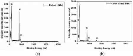
Fig.2.EDS analysis of(a)EHNT and(b)inhibitor loaded EHNT.
Electrochemical analyser,CH Instruments(Model 600E Series)was used to carry out electrochemical impedance spectroscopy(EIS)and potentiodynamic polarization studies.The three-electrode configured system consisted of platinum electrode as counter electrode,saturated calomel electrode(SCE)as reference electrode and coated substrates as working electrode with 1 cm2area of exposure.3.5wt % NaCl solution was used as exposure medium for measuring open circuit potential(OCP).A 10mV amplitude AC signal was used in the frequency range of 0.01Hz to 1MHz for the electrochemical impedance spectroscopic measurements.ZViewR○software was used to fit the experimental data obtained from EIS measurements.±0.3V of potentials were applied corresponding to OCP with 0.8mV/s scan rate for polarization measurements.EIS and potentiodynamic polarization measurements for the uncoated and coated AZ91D substrates were carried out in 3.5wt % NaCl solution for 120 h.
3.Results and discussion
3.1.Morphological and BET(pore volume and surface area)analysis of HNTs
The morphological analysis of inhibitor loaded and unloaded HNTs and EHNT was carried out using TEM.The morphology of HNTs was observed to be of tubular structure and it retained the same even after etching as shown in Fig.1.The lumen diameter of HNT was found to be in the range of 10–15nm,whereas that of EHNTs was found to be in the range of 35–45nm.
The elemental composition of inhibitor loaded and unloaded EHNT as shown in Fig.2 confirmed presence of alumina and silica and the appearance of Zr4+,which was loaded into the lumen.
Though Ce3+was also loaded into the lumen,peaks of Ce3+did not show up in EDAX analysis,since it was present in an amount lower than the detection limit of the instrument.Further,the loading of corrosion inhibitors was confirmed by BET surface area and pore volume analysis as shown in Fig.3.
The enhanced surface area and pore volume after etching confirmed dealumination of HNT.Further,the decreased surface area of inhibitor loaded HNT and EHNT indicated that the inhibitor may have either got loaded in the lumen and/or adsorbed on the surface.It could be observed that the pore volume of inhibitor loaded HNT and EHNT has decreased,which confirmed the inhibitor loading into the lumen.
3.2.XRD analysis
XRD patterns of HNTs and EHNTs are shown in Fig.4.HNT has shown d001peak at 7.3A° corresponding to multilayer tubular structure of alumino silicate.d001peak did not show any shift to lower angles,which indicated that etching of HNT has started from innermost layer and there is no intercalation of H2SO4into the interlayer spacing.This also showed that,only alumina layer has been removed without affecting the crystal structure of HNT.
3.3.Electrochemical measurements of bare and coated AZ91D substrates
The hybrid sol-gel coating layer was found to be quite dense as seen from the SEM image of the surface and cross section shown in Fig 5.The coatings that were generated by dip coating technique were found to have thickness in the range of 3–5μm as measured using the thickness gauge PosiTectorR○6000.This was also confirmed from the crosssectional analysis,as shown in Fig.5b.
EIS and potentiodynamic polarization measurements of bare and coated AZ91D substrates were performed with exposure to 3.5wt% NaCl solution for 120h.The EIS results were fitted with equivalent electric circuit for uncoated and coated substrates as shown in Fig.6,where charge transfer resistance(Rct)and electrical double layer capacitance(CPEedl)were connected in parallel.Coating resistance(Rcoat)and coating capacitance(CPEcoat)represent coating properties.Deviation from ideal behaviour of Nyquist plots was indicated by replacing pure capacitor with a constant phase element.The pseudo capacitance can be correlated to phase element from following expression:

Fig.3.BET(a)surface area and(b)pore volume analysis of inhibitor loaded and unloaded,HNTs and EHNTs.
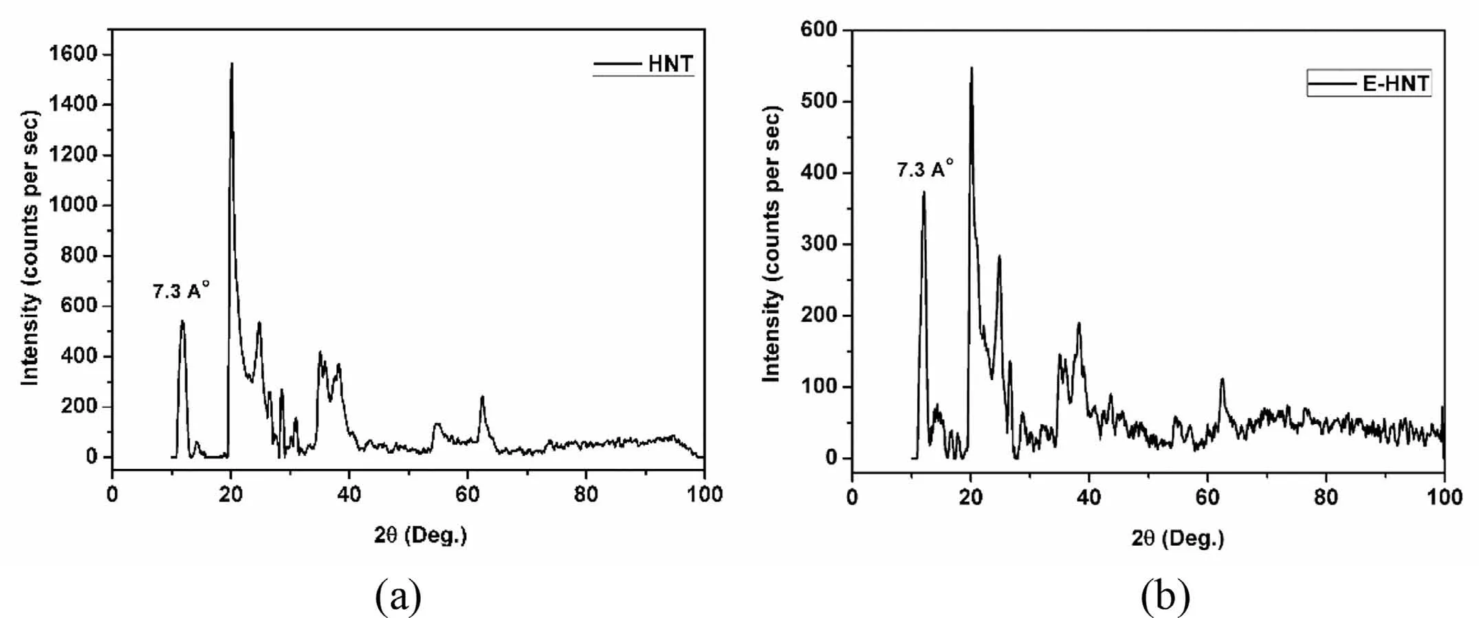
Fig.4.XRD patterns of(a)HNTs and(b)EHNTs.

where,C is pseudo capacitance in F/cm2;Q0is Constant Phase Element in S-secn/cm2;n is frequency factor and R is resistance inΩ.
The Nyquist plots for bare AZ91D and AZ91D coated with sols based on different corrosion inhibitors loaded in HNT are as shown in Fig.7.The EIS fitting parameters were obtained using appropriate equivalent electric circuit as shown in Table 1.Oxides/hydroxides of Mg are considered as unstable at lower pH and dissolves to form Mg2+whereas,at higher pH they are more stable and forms passive film.The electrochemical measurements being carried out in 3.5wt% NaCl(pH-7.2),bare Mg substrates have shown more corrosion resistance after 120h.After prolonged exposure of 120h,the coatings based on HQ loaded in EHNT have shown higher corrosion resistance and lower capacitance as compared to HQ loaded in HNT.It could indicate that,higher concentration of HQ will give effective corrosion protection to AZ91D after longer durations of exposure due to thick film of chelate complexes formed as availability of free Mg2+cations will be more.
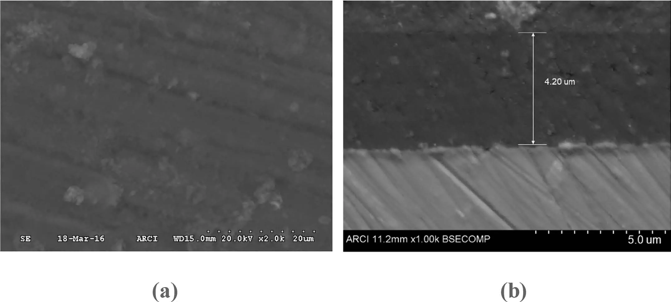
Fig.5.SEM images showing(a)surface morphology and(b)cross sectional view of coated AZ91D.

Fig.6.Equivalent circuit used for fitting impedance data for(a)bare and(b)coated AZ91D substrates.

Table 1EIS fit data for bare and coated with different corrosion inhibitor loaded HNT and EHNT based sols on AZ91D substrates after 120h.
Ce3+-Zr4+-HNT based coatings have shown higher corrosion resistance with lower capacitance,which could be attributed to formation of stable passive films of cerium oxide.However,there could be the possibility that,with higher release of cationic inhibitor,the oxide film formed became more porous,allowing diffusion of corrosive medium thereby showing higher capacitance for Ce3+-Zr4+-EHNT coatings.Similar case was observed with MBT based coatings,where inhibitory action of O,S and N results in adsorption of inhibitor on the surface by displacing molecules of corrosive medium.However,the higher release of inhibitor from EHNT might have resulted in weak adsorption and resulted in higher capacitance.
Potentiodynamic polarization measurements of bare and coated AZ91D substrates were carried out with exposure to 3.5wt% NaCl solution(pH–7.2)for a duration of 120h and the results are shown in Fig.8.Corrosion current,corrosion potentials,corrosion rates and cathodic/anodic slopes obtained using Tafel extrapolation method are compared in Table 2.
Potentiodynamic polarization results are in consistence with the results obtained from EIS studies where,loading higher amount of Ce3+-Zr4+and MBT in EHNT has accelerated the corrosion rate whereas,HQ was found to give better corrosion protection when loaded in higher amount.
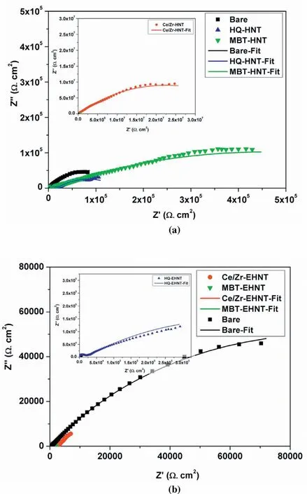
Fig.7.Nyquist plots for bare and coated with different corrosion inhibitor loaded(a)HNT and(b)EHNT based sols on AZ91D substrates after 120h.

Table 2Tafel fit parameters from polarization data obtained for bare and different corrosion inhibitor loaded HNT and EHNT based sol coated AZ91D substrates after 120h exposure to 3.5% NaCl.
It is expected that the etched HNTs should accommodate more inhibitors and their release also should be high giving rise to higher corrosion protection during coating damage.However,after 120h of exposure,the corrosion current was high(lower corrosion protection)for coatings based on Ce3+-Zr4+loaded in EHNT,when compared to that of coated samples with Ce3+-Zr4+loaded in HNT.On the other hand,HQ loaded HNT based coatings have shown highest corrosion current(lowest corrosion protection),whereas HQ loaded EHNT has shown lowest corrosion current.In case of MBT,loaded in both the HNT as well as the EHNT,the corrosion currents were not always the lowest among the corrosion inhibitors studied.Hence,it was concluded that MBT was not so effective in providing corrosion inhibition on Mg alloy AZ91D and so,not considered for further studies on release rate kinetics.
The corrosion inhibition of HQ based coatings could be attributed to formation of a complex of chelate of HQ on the surface of Mg such as,bis(8-hydroxyquinoline)magnesium(MgQ2),which may inhibit the active sites and prevent the permeability of the corrosive species[34].Hence,due to lower amount of HQ loaded in HNT,the chelate film that has formed after its release from the HNT might have depleted easily with longer durations of exposure.Alternately,the minimum amount required to form the chelate film could be higher in case of HQ and since the amount of inhibitor loaded inside the HNT is less in case of as-received HNT,the active corrosion protection may not be effective.However,in the case of HQ loaded inside EHNT,the required amount of HQ could have been released and hence,the corrosion protection is higher,when compared to coatings based on HQ loaded in as-received HNT.
Since the expected self-healing effect for the corrosion inhibitors are pH dependent,in order to explain the results from EIS and potentiodynamic polarization measurements for HNT and EHNT in case of Ce3+-Zr4+and HQ,release rate experiments were carried out under different pH conditions of 3.5%NaCl solution.
3.4.Release rate of corrosion inhibitors Ce3+-Zr4+and HQ along with kinetics of Ce3+-Zr4+release
The release rate profiles of Ce3+-Zr4+,HQ loaded in HNT and EHNT at different pH values are depicted in Figs.9 and 10,respectively.The objective of this experiment was to investigate the effect of pH of aqueous NaCl solution(pH 3,7,8.5 and 10.2)on the percentage release of the corrosion inhibitors as a function of time.The percentage release of the corrosion inhibitors was found to increase as a function of time initially and then attained steady state.It can be seen that the release for HQ and Ce3+-Zr4+at any particular pH are higher for EHNT when compared to HNT.The higher release for inhibitors loaded in EHNT could be due to the higher amount of inhibitor loaded inside lumen as expected,which was already confirmed with BET surface area and pore volume analysis.It can also be seen that there was a drastic increase in release rate during the first one hour of stirring(that simulated the conditions of an external damage),after which time,the values attained a steady state.
Further,it was found that,percentage release of Ce3+-Zr4+(Fig.9)was highest at pH 7 followed by pH 8.5,pH 10.2 and pH 3.In case of HQ(Fig.10),the percentage release was highest at pH 3,followed by 10.2,8.5 and 7.The reason for very low release of Ce3+-Zr4+in pH 3 could be due to the presence of complex of MAA that hinders the release of loaded compound in HNT,according to Yendluri et al.[35].At higher pH values,the MAA complex is not stable and hence,releases the cationic corrosion inhibitors.In this case,Ce3+-Zr4+were loaded in HNT and EHNT along with MAA as the complex forming stabilizing agent for Ce3+and Zr4+.Hence,release of Ce3+-Zr4+could be lower due to presence of MAA.Fig.11 shows release profiles of Ce3+-Zr4+and HQ loaded in HNT and EHNT at pH-7.
Since the percentage release rates for the initial one hour was the maximum,the kinetics of the release was further studied using the data obtained for the first one hour duration,only for the Ce3+-Zr4+inhibitor.Various kinetic models were analysed for release of corrosion inhibitor Ce3+-Zr4+from HNT and EHNT to correlate the data and increased understanding of the release mechanism.The models used are the ones that have been reported to understand the release of drugs from controlled drug delivery systems[31].Assuming that the self-healing mechanism is similar to the controlled release of drugs from drug delivery systems,these models were used to study the release data.The Korsmeyer-Peppas model assumes release for cylindrical shaped matrices.Since here the HNTs had a cylindrical shape,this model was also included for analysing the release data.Accordingly,the Ce3+-Zr4+release data from HNT and EHNT at various pH values as a function of time was fitted to zero-order(Eq.(1)),firstorder(Eq.(2)),Higuchi(Eq.(3)),Hixson-Crowell(Eq.(4))and Korsmeyer-Peppas(Eq.(5))models.

Fig.8.Polarization curves for bare and different corrosion inhibitor loaded(a)HNT and(b)EHNT based sol coated AZ91D substrates after 120h exposure.

Qt=amount of Ce3+-Zr4+released after time t,Q0=Initial amount of Ce3+-Zr4+in the solution(in this case Q0=0),k0=Zero order release constant(concentration/time)

Mt=Concentration of Ce3+-Zr4+present in HNT at time t,M∞=Initial concentration of Ce3+-Zr4+in HNT,k=First order rate constant(time−1)

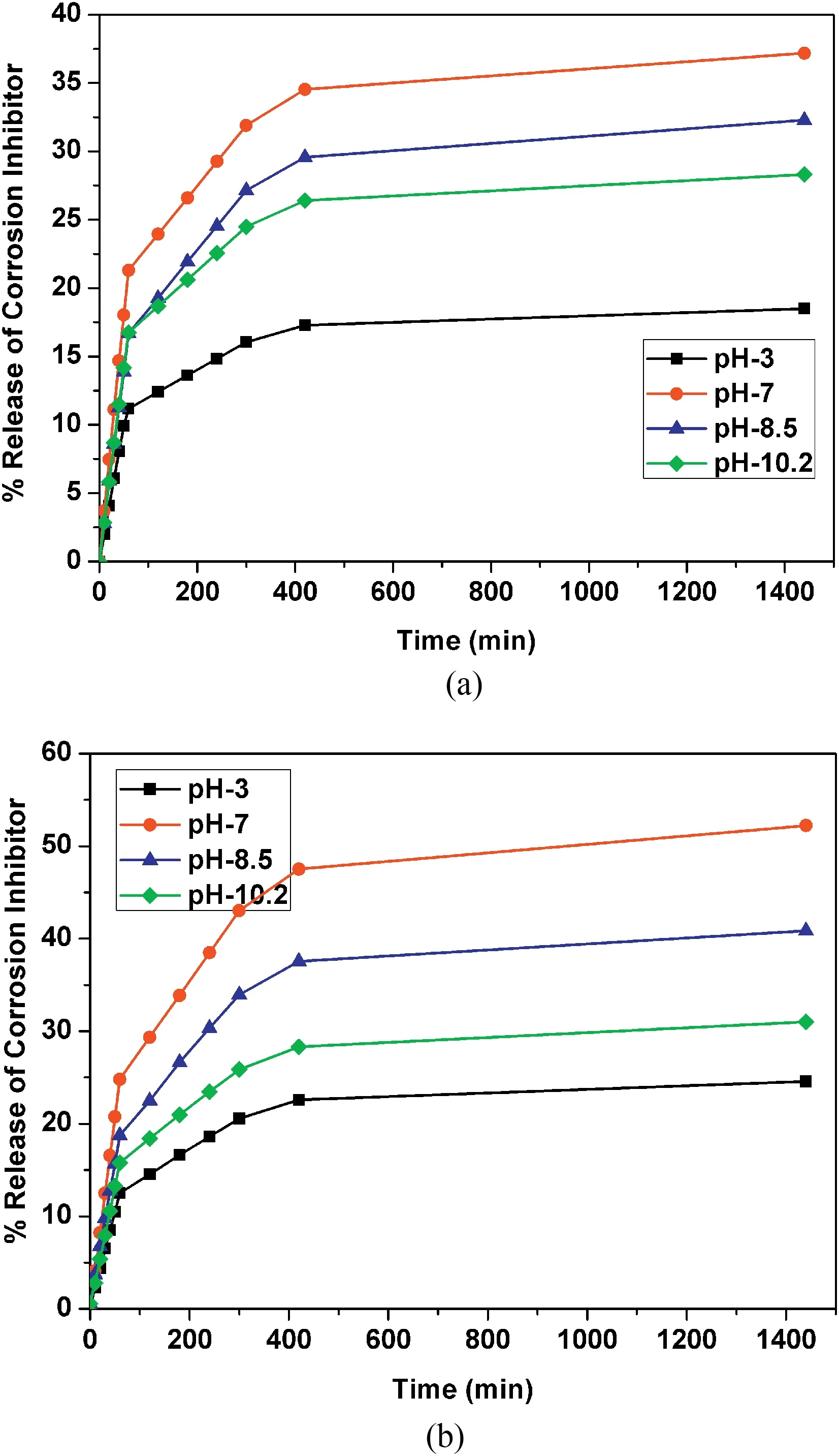
Fig.9.Release profiles of Ce3+-Zr4+loaded in(a)HNT and(b)EHNT.
Qt=amount of Ce3+-Zr4+released after time t,KH=Higuchi dissolution constant

Wt=Remaining amount of Ce3+-Zr4+in HNT at time t,W0=Initial amount of Ce3+-Zr4+in HNT,Ks=Constant incorporating the surface-volume relation

Qt=amount of Ce3+-Zr4+released after time t,Q0=Initial amount of Ce3+-Zr4+in the solution,
kt=Release rate constant,n=Release exponent
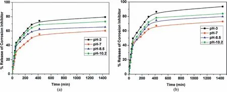
Fig.10.Release profiles of HQ loaded in(a)HNT and(b)EHNT.

Fig.11.Release profiles of Ce3+-Zr4+and HQ loaded in HNT and EHNT at pH-7.
Figs.12 and 13 depicted the use of zero-order,first-order,Higuchi,Korsmeyer-Peppas and Hixson-Crowell model for fitting Ce3+-Zr4+release profile from HNT and EHNT up to 1h,respectively.The respective rate constants and R2values are mentioned in Tables 3 and 4.The rate constant values have shown the rate of diffusivity of corrosion inhibitor which could be correlated with corrosion inhibition ability of coatings.The preferred mechanism of release of the inhibitor is a zero-order one,since it is time-independent release.It could be observed from Tables 3 and 4 that zero order and Korsmeyer-Peppas models have shown better fit as compared to other models and of the two,the Korsmeyer-Peppas model was seen to be the best fit for the data obtained.Korsmeppas model gave information about diffusion mechaf corrosion inhibitors in NaCl solution.As mentioneyer-nismed in Tables 3 and 4,diffusional release coefficient,n≈1,whichndicated that the diffusion mechanism followed zero order P o i time independent release.The release profile was also fitted for the duration from 2h to 24h.It was observed that,all the models fitted the release profile in the similar manner for both durations.Hence,it could be concluded that there is no change in reaction order after the release rate attained the steady state.
It is always desirable that for a self-healing release based coating,the release of the inhibitor is slow and steady which persists over a long time.In case of EIS and potentiodynamic polarization measurements,the pH of the 3.5% NaCl solution is 7.2 and since in case of Ce3+-Zr4+,the percentage release as well as the release rate is highest at pH 7,the inhibitors are also released at a very fast rate at pH 7.Though the amount of inhibitor available in the EHNT is high(also confirmed from BET surface area and pore volume analysis),they are all released very fast during the first hour itself and hence,the self-healing effect is not lasting in case of EHNT for long time.This is seen from the high Icorrvalues for coatings from Ce/Zr-EHNT.On the contrary,in the case of HQ,the lowest release happens at pH 7.Since,EHNT has more inhibitor loading in it,the HQ in EHNT gets released very slowlybut in higher quantities compared to HQ in HNT and hence,has shown the least corrosion current confirming better selfhealing effect for HQ in EHNT.

Table 3Comparison of parameters of various models for release of corrosion inhibitor from HNT.
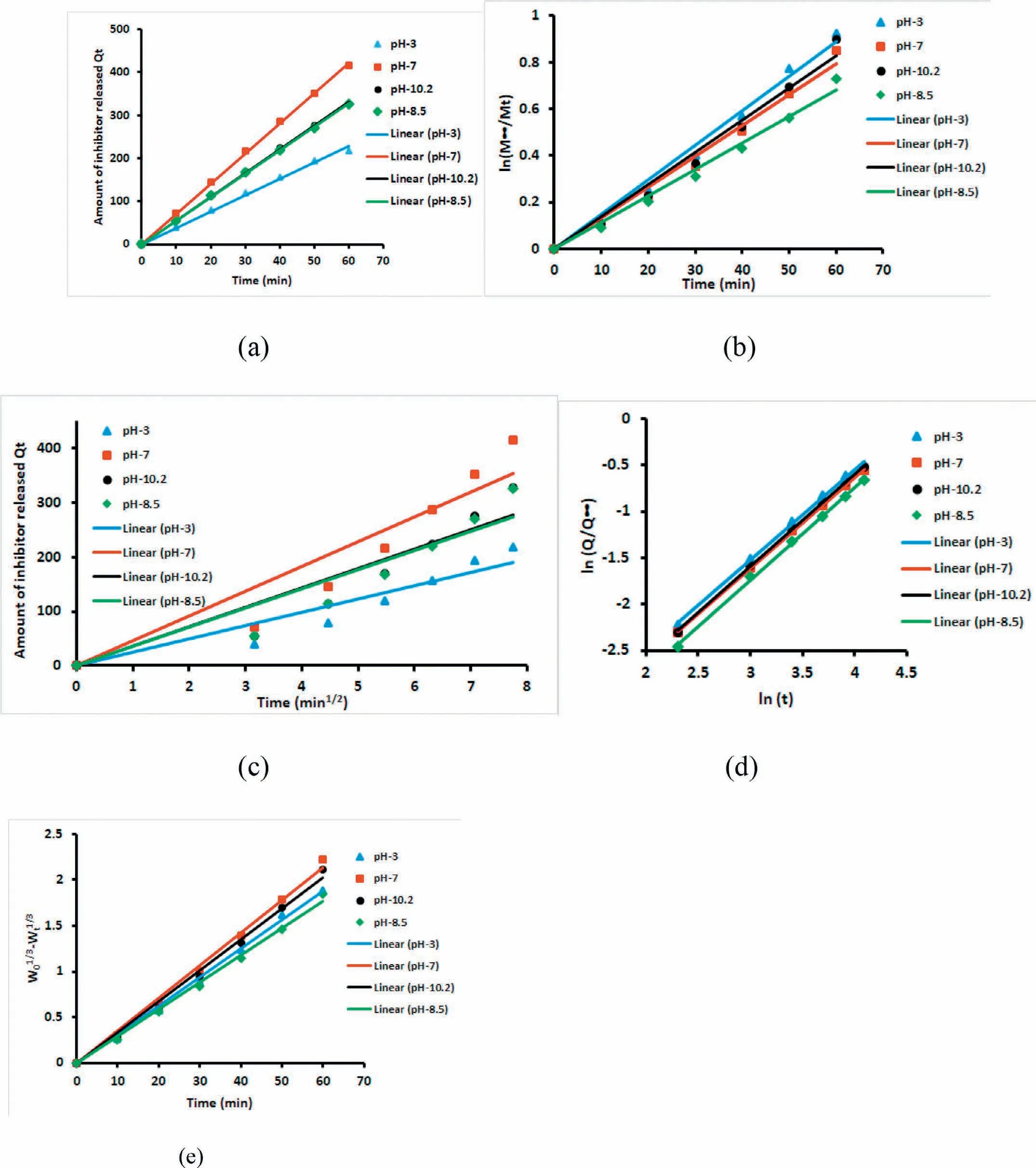
Fig.12.Release rate models for Ce3+-Zr4+release from HNT at different pH,(a)Zero order,(b)first order,(c)Higuchi model,(d)Korsmeyer-Peppas model and(e)Hixson-Crowell model.

Fig.13.Release rate models for Ce3+-Zr4+release from EHNT at different pH,(a)Zero order,(b)first order,(c)Higuchi model,(d)Korsmeyer-Peppas model and(e)Hixson-Crowell model.

Table 4Comparison of parameters of various models for release of corrosion inhibitor from EHNT.
Hence,on the basis of EIS and potentiodynamic polarization studies and release study,it can be concluded that Ce3+-Zr4+could work as best corrosion inhibitor for the HNT based self-healing coatings under the conditions of neutral and basic pH for application on AZ91D and HQ could work very well for the EHNT based coatings under similar pH conditions.
4.Conclusion
Different corrosion inhibitors such as cationic Ce3+-Zr4+,HQ and MBT were successfully loaded into as-received and etched HNTs as confirmed from morphology,SEM-EDS and BET analysis.The acid treatment for etching the lumen of HNTs enhanced the inhibitor loading capacity without affecting the crystal structure of HNTs.Ce3+-Zr4+has shown higher release under neutral and basic pH conditions,but percentage release was observed to be less as compared to other inhibitors.The quantitative analysis of release of corrosion inhibitor from HNT and EHNT was carried out using various semi-empirical kinetic models and the Korsmeyer-Peppas model was confirmed to be the best fit.Under conditions of neutral pH,after prolonged duration of exposure,Ce3+-Zr4+based coatings have revealed better corrosion protection ability when loaded in HNT,whereas HQ shown better corrosion protection properties when loaded in EHNT owing to higher amount of loading.The present investigations have compared for the first time in literature,the kinetics of release of inhibitor loading in HNT and EHNT for different corrosion inhibitors.
Declaration of Competing Interest
None.
Acknowledgement
The authors are thankful to Director,ARCI,Hyderabad for the constant support and motivation throughout the entire duration of work.The authors would like to thank Dr.N.Rajalakshmi,Dr.K.Suresh,M.Ramakrishna,K.R.C.Soma Raju and G.V.R.Reddy for the data acquisition of BET,XRD,TEM,FESEM and SEM-EDS analysis,respectively.
杂志排行
Journal of Magnesium and Alloys的其它文章
- Recent developments and applications on high-performance cast magnesium rare-earth alloys
- Surface characterization and corrosion behavior of calcium phosphate(Ca-P)base composite layer on Mg and its alloys using plasma electrolytic oxidation(PEO):A review
- Towards developing Mg alloys with simultaneously improved strength and corrosion resistance via RE alloying
- Magnesium matrix composite reinforced by nanoparticles–A review
- The design of Co3S4@MXene heterostructure as sulfur host to promote the electrochemical kinetics for reversible magnesium-sulfur batteries
- A new die-cast magnesium alloy for applications at higher elevated temperatures of 200–300°C
