Four Wheel Independent Drive Electric Vehicle Lateral Stability Control Strategy
2020-11-05YantaoTianXuanhaoCaoXiaoyuWangandYanboZhao
Yantao Tian, Xuanhao Cao, Xiaoyu Wang, and Yanbo Zhao
Abstract—In this paper, a kind of lateral stability control strategy is put forward about the four wheel independent drive electric vehicle. The design of control system adopts hierarchical structure. Unlike the previous control strategy, this paper introduces a method which is the combination of sliding mode control and optimal allocation algorithm. According to the driver’s operation commands (steering angle and speed), the steady state responses of the sideslip angle and yaw rate are obtained. Based on this, the reference model is built. Upper controller adopts the sliding mode control principle to obtain the desired yawing moment demand. Lower controller is designed to satisfy the desired yawing moment demand by optimal allocation of the tire longitudinal forces. Firstly, the optimization goal is built to minimize the actuator cost. Secondly, the weighted least-square method is used to design the tire longitudinal forces optimization distribution strategy under the constraint conditions of actuator and the friction oval. Beyond that, when the optimal allocation algorithm is not applied, a method of axial load ratio distribution is adopted. Finally, CarSim associated with Simulink simulation experiments are designed under the conditions of different velocities and different pavements. The simulation results show that the control strategy designed in this paper has a good following effect comparing with the reference model and the sideslip angle β is controlled within a small rang at the same time.Beyond that, based on the optimal distribution mode, the electromagnetic torque phase of each wheel can follow the trend of the vertical force of the tire, which shows the effectiveness of the optimal distribution algorithm.
I. Introduction
THE road traffic accidents occur frequently in recent years,much attention has been paid on the vehicle active safety studies [1]–[3]. Electric vehicle lateral stability, as an important part of vehicle active safety, has obtained the extensive and in-depth research by domestic and foreign scholars [4]–[8].
Tabtiet al. put forward a new control method for the independent drive electric vehicle stability system, which described the vehicle dynamics as a linear hybrid system, and designed mixed model predictive controller. The experiment verifies that the controller makes the yaw angular velocity well follow the reference, ensures the vehicle driving safety and improves the vehicle stability [9]. Oharaet al. put forward a strategy of stability control based on the estimated information, the model reference control method is used for the composition of the controller, and this controller is able to make the yaw rate follow the reference yaw rate robustly.Numerical simulation is implemented with the consideration of a gust of wind and vehicle modeling error. Also, a vehicle experiment on the road is conducted [10]. Canaleet al.designed a reference generator to improve vehicle handling and provide the desired yaw rate value. After that, a closed loop controller was designed using the second-order sliding mode (SOSM) methodology to guarantee robust stability in front of disturbances and model uncertainties [11]. Peeie proposed a direct yaw moment control (DYC) using the front tire steer angle to increase the stability of the small electric vehicle with HMBS, and a kind of state feedback controller was presented. But several conditions must be met in the simulation to increase the stability of the vehicle: 1) The velocity of the vehicle must be constant; 2) The changes of the lateral velocity must be small [12]. Nasriet al.demonstrated the possibility of an improved four wheel vehicle stability which uses four independent drive wheels for motion by using the sliding mode control [13]. Namet al. put forward a method to estimate vehicle side-slip angle based on the lateral tire force sensor and improve the wheel motor drive electric vehicle stability. The extended Kalman filter (EKF) state observer is designed to estimate vehicle side-slip angle. In addition, a vehicle stability controller was designed, and a simulation experiment was implemented to verify the effectiveness [14]. Nahidiet al. proposed a modular control structure for optimal integrated vehicle longitudinal and lateral stability control. The optimal torque distribution adopted the HCC strategy, which minimizes these CG discrepancies by considering the errors between the target and actual vehicle CG forces and yaw moment [15]. Zhanget al.proposed a kind of hierarchical framework to reduce the complexity for design and analysis. A high-level controller was designed to generate the desired longitudinal dynamics,and at the lower level, an adaptive sliding-mode controller was designed. Numerical simulations demonstrated the robustness of the controller [16]. Xiaet al.presented a tracking control method for the lateral motion of an autonomous land vehicle (ALV), which is based on active disturbance rejection control (ADRC) scheme and differential flatness theory [17]. Khosravaniet al. proposed a new torque distribution method which can contain multi-objective functions such as force tracking at CG, minimum actuator adjustments, etc. And several physical constraints such as constraint for avoiding wheel overspin/lock were incorporated into the allocation task. Numerical simulations demonstrated that it could improve the vehicle stability [18]. Rafailaet al.proposed a nonlinear model based predictive control strategy for the autonomous control of the steering system for ground vehicles. According to the simulation results, this approach could provide good performances in practical use [19].
To sum up, the study of stability control system of the vehicle mainly concentrates on the upper controller development and design at present. The allocation algorithm of the lower controller is widely used by axial load distribution ratio method, but the utilization rate of each wheel is not high, which affects the vehicle’s stability and safety.Therefore, in this paper, firstly, the control allocation algorithm is studied as the research key, which is used to distribute longitudinal force of each tire reasonably. The weighted least-square method is adopted to design the tire longitudinal forces optimization distribution strategy. Beyond that, when the optimal allocation algorithm does not apply, the method of axial load ratio distribution is adopted. Secondly, a new hierarchical structure of lateral stability controller is designed which adopts the method of sliding mode control combined with optimal allocation algorithm.
The purpose of this paper is to design a kind of lateral stability control strategy and improve the vehicle stability in more critical conditions. And the control strategy is double layered system. Upper controller adopts the sliding mode control principle to obtain the desired yawing moment demand. Lower controller is designed to follow the desired yawing moment demand by optimal allocation of the tire longitudinal forces. Finally,CarSimassociated withSimulinksimulation experiments are designed under the conditions of different velocities and different pavements.
The main contributions of this paper can be described as two points: 1) A kind of vehicle tire longitudinal forces optimization distribution strategy is designed, and the optimization goal is built to minimize the actuators cost.According to this approach, the utilization rate of each wheel can be increased, and vehicle stability and safety can be improved. 2) The optimal allocation algorithm will not apply when the vehicle is travelling on the low adhesion pavement,because when the coefficient of friction is very low, the longitudinal force constraint may appear empty set. So, in this case, the distribution mode contains the switch of the optimal allocation and the axle load distribution. According to this approach, the effectiveness of actuator can be guaranteed.
This paper is organized as follows. In Section II, a lateral dynamics model is designed based on the vehicle yawing plane model which is used to the design of upper controller. In Section III, firstly, the lateral stability system control strategy and basic frame are described. Secondly, a kind of vehicle reference model is calculated. After that, the sliding mode controller is designed to control the vehicle tracking vehicle reference model. In Section IV, two different control distribution methods are designed, the first one uses the quadratic programming method, and the other one is the axle load proportional allocation algorithm. In Section V,Carsim/Simulinksimulation experiments are conducted under the condition of different velocities and different pavements.According to the lateral stability control system simulation experiments, the validity of the control strategy and the distribution algorithm designed are demonstrated.
II. Vehicle Dynamics Modeling
The vehicle system is a kind of high degree of freedom and strong nonlinear system which are difficult for control design.Therefore, in order to simplify the vehicle model, it is necessary to make the following assumptions [20]: 1) the vehicle runs on a horizontal road; 2) the impact of vehicle vertical load transfer is not considered; 3) the two front wheel angles are equal and the front and rear axle wheelbases are approximately equal; 4) the vehicle tire and suspension remain relatively vertical state to the ground.
A. Lateral Dynamics Model
Lateral dynamics model of this paper is designed based on the vehicle yawing plane model. The main difference from the traditional vehicle dynamic model is that this paper takes the direct yaw moment as an additional input variable, which is based on the independent output torque of each wheel [21].The vehicle’s yawing plane is shown in Fig. 1, and the parameters of vehicle dynamics are given in Table I. The vehicle lateral dynamics model and the yawing moment balance equation at the barycenter position are established as follows:

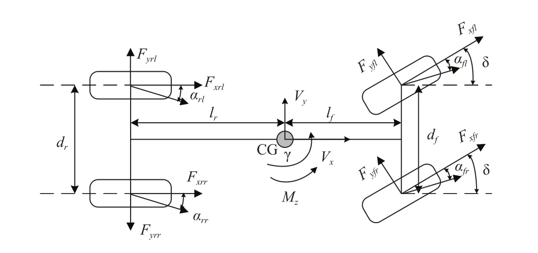
Fig. 1. Vehicle yaw plane four wheel model.
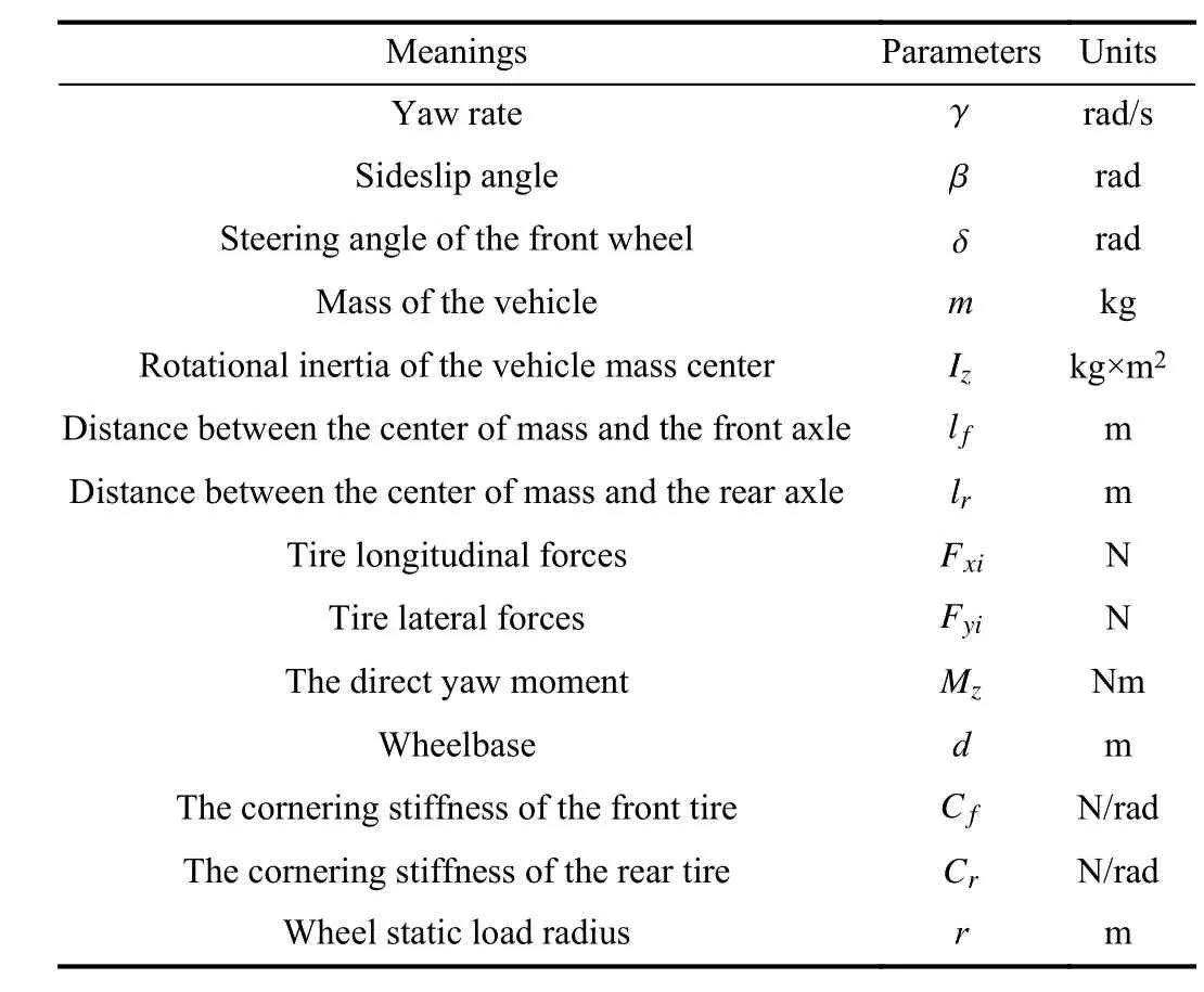
TABLE I Parameters of Vehicle Dynam ics
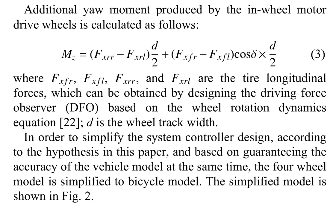
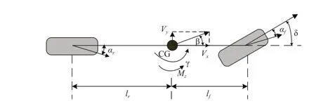
Fig.2.Vehicle linear bicycle dynamicmodel.
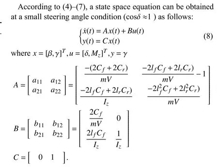
According to the above vehicle linear bicycle dynam ic model,the simplified vehicle lateral and the yaw dynam ics equation are described as follows:


B.Wheel Dynamics Model
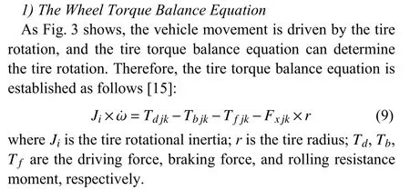
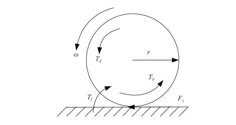
Fig.3.Thewheel torque balance diagram.
2)The Wheel Vertical Load
Ignoring the vehicle suspension system,the vehicle can be taken as a rigid body.According to the model vehicle dynam ic model and the rigid mechanics principles,the calculation formulas of wheel vertical load are shown as follows[20]:
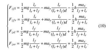

Fig.4.Theelectric vehicle lateral stability control system structure diagram.
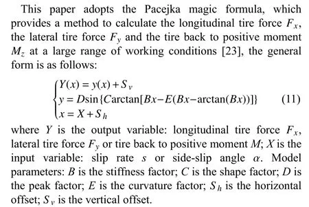
C.Tire Model
III.Direct ly Yaw ing Moment Con t rol ler
A.The Lateral Stability System Control Strategy
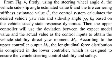
Lateral stability control goal is to enhance the vehicle steering stability and ensure the vehicle to track the expected trajectory at the same time.Thewhole system isdivided into a two-layer structure, the upper controller is designed for the yaw rate and side-slip angle tracking control.Based on the yaw moment requirement and considering constraints at the same time,a lower controller is designed to optimize the motor torque distribution and ensure the electric vehicle stability.Fig.4 is the lateral stability control system structure adopted in thisarticle.
B. Reference Model
According to the sideslip angleand the yaw rate steady-state response,which are produced by the driver demands(the steering angle and speed), the vehicle reference model can be built. Normally,the vehicle steady state responseβ˙=γ˙=0 is used as the referencemodel.According to(4),(5)and the tire cornering stiffness values,the desired vehicle sideslip angle and yaw rateare defined as follows:
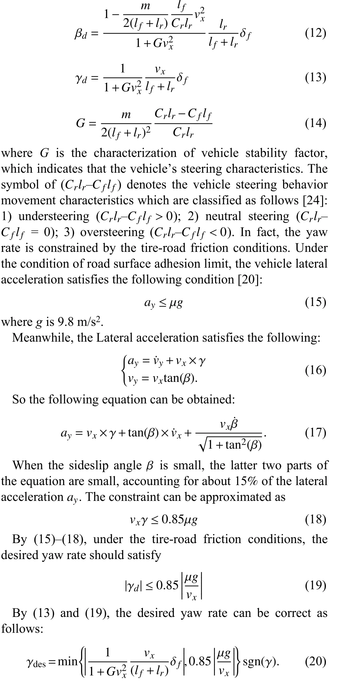
Generally speaking,the maximum value of the stability vehicle sideslip angle changes w ith the road adhesion conditions.On the good road condition,the sideslip angle stability value is greater than thaton theworse road adhesion conditions[25].According to this experience,this article selects road adhesion coefficient to lim it the valueof

To sum up,the desired vehicle sideslip angle is revised as follows:

C.Sliding Mode Controller
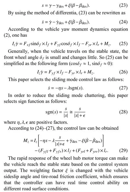
For the vehicle stability control system, the controleffectof general linear controllers usually can not satisfy the requirementof improving the vehicle steering control stability and safety.According to this,this paper chooses the sliding mode controller to control the vehicle to track the desired yaw rate and side-slip angle,and the sliding mode surface[26]is chosen as follows:
IV.Con t rol Torque A l loca tion A lgor ithm
The controlof electric vehicles has been conducted inmany research reports,such as using linear quadratic regulator or state feedback controller to maintain the vehicle driving stability.However,in order to make full use of the vehicle’s performance potential,a well-designed control distribution method is required.
A.Optimization Goal
The vehicle total tire longitudinal force and total yaw moment equationsareas follows:
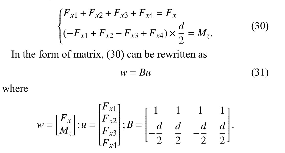
The equation can use the quadratic programmingmethod to solve.Based on the quadratic programm ing theory,firstly,the optimal objective function and the constraint conditions should be determined.In this paper,we choose the sum of squaresof four wheel longitudinal forcesand lateral forcesdivided by the square of the product of the vertical loadand the friction coefficient as the optimization objective function,which can be used to express the vehicle stability margin.Generally, the higher of the tire utilization,the lower the vehicle stabilitymargin When the objective function value is close to 1, the adhesion between tire and road w illbe close to its lim it,and the vehicle is in a critical state of losing stability at this time.So in this paper,the optimization goal is to minimize the objective function and ensure the maximization of the vehicle stability margin[27].The objective function isexpressed as[28]
As(34)shows,in this paper, the optim ization objective function is the variantof theminimum sum of squares of the tire utilization.The lateral force is ignored,and the tire utilization minimum is produced by the selection of the longitudinal forcewhich is used in the objective function.To be clear,in the actual situation, the longitudinal and lateral forces cannot be completely independent.We can think about it in a different way,the optimization objective function adopted in this paper can minim ize the actuator control cost,and ensure the vehicle driving stability.The optim ization goal is to distribute the longitudinal force and torque,which makes the motor to retain a bigger margin[29]in sudden unstable situation and makes the vehicle havegreater ability to own the initiative to maintain or change the vehicle state and enhance the vehicle safety and stability.Italso has certain significance for thestability of control systems.
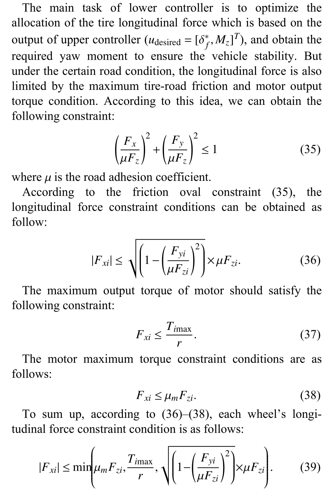
B.Constraint Conditions
C.The Optimization Allocation Algorithm
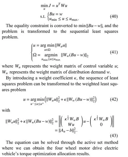
According to(31),(34),and(36), the follow ing quadratic programm ing standard isobtained:
D.The Axle Load Proportional Allocation Algorithm
The optimal allocation algorithm w ill be no longer applicablewhen the vehicle is running on the pavement w ith poor adhesion,because the coefficient of friction is very low,the longitudinal force constraint(39) may result in an empty set.In this case,for the vehicle stability control system,the vehicle tire longitudinal force distribution adopts themethod of axial load ratio distribution.The total driving force and the total yaw ing moment have been distributed according to the proportion of front and rear axle load,axle load valuesas
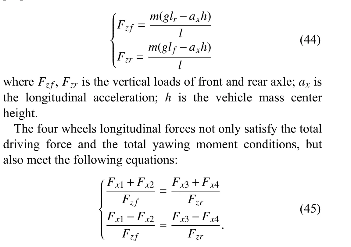
So each wheel longitudinal force by axial load proportion distribution can be obtained as follows:
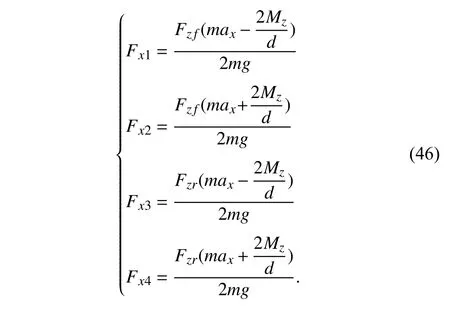
V.La tera l Stabil ity Con t rol System Simu la tion Resu l ts
This section is the study and analysis of the lateral stability control system simulation experiments.Compared w ith the open-loop experiment,the closed-loop driver model can better reflect the driver’s real driving process.In this simulation experiment, weadopt double line conditions in different speed and road surface conditions, respectively.The parameters of theCarsimvehiclemodel are shown in Table II.
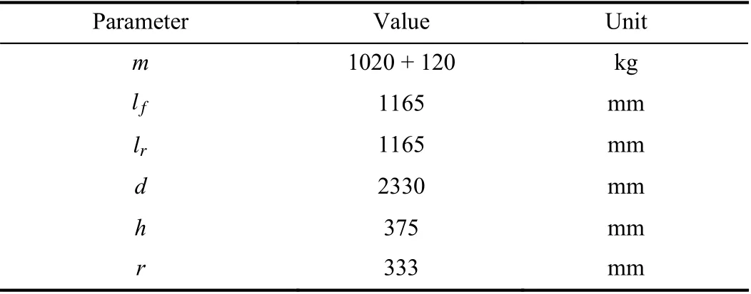
TABLE II Vehic le Pa rameters
A.The Simulation Results With Initial Speed 60 km/h Under High Adhesion and Low Adhesion Road Surface Condition
Figs.5 and 6 show the simulation results w ith the vehicle initialspeed 60 km/h when the road friction coefficient is 0.9.Fig.6 shows the vehicle yaw rate and sideslip angle tracking errors.And according to Fig.6,the tracking errors based on the optimal distribution mode is smaller than the tracking errors based on the average distribution mode.Figs.5(a),5(b),and Fig.6 show that the valuesof the vehicle yaw rate and the vehicle sideslip angle have good follow ing performances for the reference values,which demonstrates that the designed controller has good control results.Fig.5(c)shows the simulation result of the vehicle four wheel vertical force;Fig.5(d)shows the simulation results of the yaw ing moment under the optim ization distribution mode,the average distribution mode and the PI controller,respectively.Figs.5(e)and 5(f)show the electromagnetic torques under the optimization distribution mode and the average distribution mode,respectively.According to Figs.5(e)and 5(f),it can be seen that the optim ization distribution mode and the average distribution mode both have good torque output results.However,according to contrast Figs.5(e)and 5(f)w ith 5(c),it can be seen that in the optimal distribution mode,the electromagnetic torque phase of each wheel can follow the trend of the vertical force of the tiremore than in the average distribution mode.Generally,under the same road surface condition,the larger the vertical force of the wheel is,the greater longitudinal driving force can be produced,so the larger longitudinal force output isalso assigned in the optimal distributionmode.This results also show the effectiveness of theoptimal distribution algorithm and itsgood performance.
Figs.7 and 8 show the simulation results w ith the vehicle initial speed 60 km/hwhen the road friction coefficient is0.4.According to Figs.7(a),7(b),and Fig.8,the designed control system has good follow ing effect for the desired yaw rate and sideslip angle.Fig.7(c)is the vehicle four wheel vertical force;From Fig.7(d),we can see that the yaw moment has sudden changes in neighborhood of 3 s to 4 s and 7 s to 8 s,and the optim ization distribution mode needs smaller yaw moment,so the vehicle has more ability to deal w ith the sudden unstable situation,which enhances the vehicle stability to a certain extent.It shows that the yaw moment control resultof the optimization distribution mode is superior to that of the average distribution mode.According to contrast Figs.7(e)and 7(f)w ith Fig.7(c), the torque output of the optimal distribution mode can also follow the trend of the vertical force of the tire.In this respect,the optim ization distribution mode is still superior to the average distribution mode.Figs.7(e)and 7(f)show that, when the pavement condition is poor,the vehicle right front wheel electromagnetic torque suddenly drops to zero in the average distribution mode in the 2–4 s and the 6–8 s, which indicates that the right front wheel is locked,and it is harm ful to the stability of the vehicle and the com fort of driving.
From Figs.5–7,under the same speed,vehicle stability control system based on the optimization distribution mode can have good control effect no matter the tire-road friction condition is good or poor.So according to the simulation results,the control result based on the optim ization distribution mode is better than that of the average distribution mode,which improves the vehicle stability on the low adhesion road.
B.The Simulation Results With Initial Speed 120 km/h Under High Adhesion and Low Adhesion Road Surface Condition
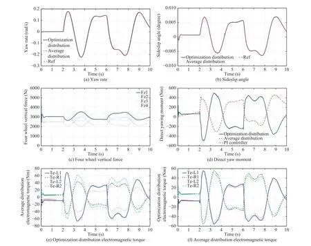
Fig.5.Resultsw ith initial velocity 60 and tire-road friction coefficient 0.9.

Fig.6.Yaw rate and sideslip angle tracking errors.
Figs.9 and 10 show the simulation results w ith the vehicle initial speed 120 km/h when the road friction coefficient is 0.9.Fig.10 shows the vehicle yaw rate and sideslip angle tracking errors.And according to Fig.10,the tracking errors based on the optimal distribution mode are smaller than the tracking errors based on the average distribution mode.Fig.9(c)denotes the vehicle four wheel vertical force;Fig.9(d)is the yaw moment figure of the optim ization distribution mode,average distribution mode and the PI control.From Fig.9(d), we can see that the required yaw ing moment based on the optimaldistribution algorithm isslightly less than thatof the average distributionmode no matterwhat controller isadopted (PIcontroller or sliding mode controller),which shows that the optimization distribution mode has better controleffectand helps to improve the vehicle stability.Figs.9(e)and 9(f)denote the electromagnetic torque inputs under the optim ization distribution mode and average distribution mode,respectively.The optimization distribution mode contains the sw itch of the optimal allocation and the axle load distribution,so there are some larger amplitude changes but it can still follow the trend of the vertical force of the tire and maintain the stability of the vehicle.
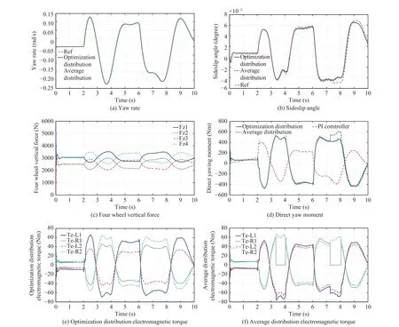
Fig.7.Resultsw ith initial velocity 60 and tire-road friction coefficient 0.4.

Fig.8.Yaw rate and sideslip angle tracking errors.
Figs.11 and 12 show the simulation resultsw ith the vehicle initial speed 120 km/h when the road friction coefficient is 0.4.From Figs.11(a)and 11(b), we can see that the vehicle control effect is inferior to the effect of the high tire-road friction coefficient but yaw rate and vehicle sideslip angle can still follow the changes of the references.Fig.11(c)is the vehicle four wheel vertical forces.Fig.11(d)denotes the vehicle yaw ing moment control result figure.From Fig.11(d),it can be seen that yaw ing moment provided by the wheel is smaller and the vehicle has better stability and security no matter what controller is adopted(PI controller or sliding mode controller).So the optim ization distribution has obvious advantages over the average distribution.According to contrast Figs.11(e)and 11(f)w ith 11(c)the torque output of the optimal distributionmode can also follow the trend of the vertical forceof the tire when the vehicle speed ishigh and the road friction coefficient is low.Finally,the optim ization distributionmode by sw itching the optimal allocation and the axle load distribution mode has better ability to maintain vehicle stability.
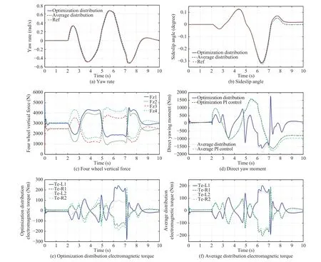
Fig.9.Resultsw ith initial velocity 120 and tire-road friction coefficient 0.9.

Fig.10. Yaw rateand sideslip angle tracking errors.
According to contrast Figs.5(b)w ith 11(b),the optimization control algorithm proposed in this paper can still have a good control effect when the sideslip angle is larger and vehicle speed is higher.Under the constraints of road conditions and motor torque, the vehicle stability and security are improved based on the reasonable distribution of the tire longitudinal force.Finally,the simulation experiments verify the effectiveness of the proposed control strategy and the distribution algorithm.
VI.Conc lusion
In this paper,a kind of electric vehicle lateral stability control strategy is put forward.It can be concluded as follows.
1)The hierarchical control structure is adopted,the upper controller and the lower controller are designed,respectively.
2)The upper controller is themotion controller.In order to guarantee the robustness and stability of the system,the sliding mode controller is applied.The vehicle sideslip angleand yaw rateare selected as control variables to calculate the yaw ing moment needed to stabilize thevehicle.
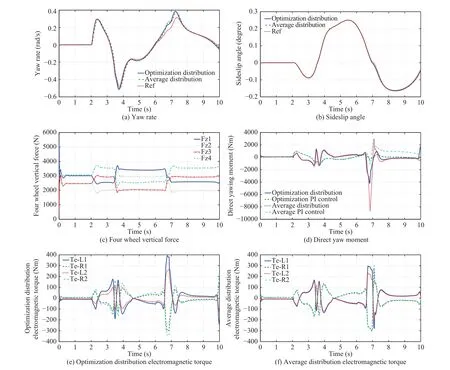
Fig.11.Resultsw ith initial velocity 120 and tire-road friction coefficient 0.4.

Fig.12. Yaw rateand sideslip angle tracking errors.
3)The lower controller adopts the sum of the squaresof tire utilization as the stability control target.Considering the road adhesion condition andmotor torque constraints,theweighted least squares method has been adopted to optim ize the tire longitudinal force distribution,which is used to guarantee the vehicle stability.
Finally,CarSimassociated w ithSimulinksimulation experiments are designed under the condition of different velocities and different pavements.The experimental results show the control strategy designed in this paper has a good follow effect in comparison w ith the referencemodel and the sideslip angleis controlled in a small range at the same time.In addition, based on the optimal distributionmode,the electromagnetic torque phase of each wheel can follow the trend of the vertical force of the tire.Generally,under the same road surface condition,the larger the vertical force of the wheel,the greater the longitudinal driving force can be produced,so the larger longitudinal force output is also assigned in the optimal distribution mode.The optimal distribution algorithm designed in this paper can also prevent wheels from locking under poor pavements and needs smaller yaw ing moments,which shows the effectiveness of the optimal distribution algorithm.Beyond that,when the optimal allocation algorithm is no longer applied,a method of axial load ratio distribution is adopted.Sometimes the optim ization distribution mode contains the sw itch of theoptimalallocation and the axle load distribution,although there are some larger amplitude changes,it can still maintain the stability of the vehicle.
In the next work, the further research and effort can be devoted to the follow ing two points:1)Online estimation of the road friction coefficient.In this paper,the road friction coefficient is a constant,and the effectivenessof the system is proved under different pavements whose road friction coefficients are fixed.But in order to carry out real vehicle experiments,it is necessary to estimate the road friction coefficient on line.2)Based on the online estimation of the road friction coefficient,some real vehicle experiments can be carried at the next work.And different experimental conditions can be considered,for example snake-like condition and double lane change test.
杂志排行
IEEE/CAA Journal of Automatica Sinica的其它文章
- Parallel Control for Optimal Tracking via Adaptive Dynamic Programming
- Sliding Mode Control for Nonlinear Markovian Jump SystemsUnder Denial-of-Service Attacks
- Neural-Network-Based Nonlinear Model Predictive Tracking Controlof a Pneumatic Muscle Actuator-Driven Exoskeleton
- Single Image Enhancement in Sandstorm Weather via Tensor Least Square
- Understanding Nonverbal Communication Cues of Human Personality Traits in Human-Robot Interaction
- A Behavioral Authentication Method for Mobile Based on Browsing Behaviors
