Consequence of reinforced SiC particles and post process artificial ageing on microstructure and mechanical properties of friction stir processed AA7075
2020-10-27DeoreBhrdwjRoMishrHiwrkr
H.A. Deore , A. Bhrdwj , A.G. Ro , J. Mishr , V.D. Hiwrkr ,*
a Department of Metallurgical and Materials Engineering, Defence Institute of Advanced Technology, Pune, 411025, India
b Naval Material Research Laboratory (NMRL), Defence Research Development Organization, Ministry of Defence, Ambarnath, 414006, India
Keywords:
ABSTRACT Friction stir processing and post process artificial ageing was successfully carried out on AA7075 with and without reinforcement of SiC particles producing defect free processed zone with uniform distribution of filler material. Effect of SiC particle reinforcement and artificial ageing times on the microstructural modifications was characterized using optical and electron microscopy,electron backscattered diffraction and X-Ray diffraction. Hardness, impact and wear tests were carried out to investigate mechanical behaviour before and after processing.Reinforcement of SiC particles during FSP and subsequent age hardening treatment brought about nearly twofold increase in hardness and impact toughness values by the combined effect of grain refinement, Zener pinning, dispersion strengthening and precipitation hardening.Significant improvement in wear resistance in terms of wear loss was also observed after processing compared to the reference material AA7075-T6. Fractured surface of post FSP age hardened AA7075 alloy exhibited features of ductile fracture during Charpy impact test.
1. Introduction
Of late, comprehensive requirement of good quality material,producing high performance at low cost has made the focus shift from unmixed to composite materials. Day by day utilization of Metal matrix composites (MMC) in different industries are expanding and it is undergoing continuous advancements,thereby gaining popularity as a potential candidate for advanced applications. Aluminium metal matrix composites (AMMCs) or simply Aluminium Matrix composites(AMC)are very much in demand for aerospace,defence and transportation applications pertaining to its high specific strength, better stiffness and improved wear resistance [1]. To accomplish further commercial escalation, a uncomplicated and cost effective method for fabrication of AMC is very crucial.Uniform distribution of filler particles(Reinforcements)and low processing cost are the two key challenges for the manufacturing of Discontinuously Reinforced Aluminum (DRA)matrix composites [2,3]. Numerous processing techniques have been instituted for the fabrication of AMCs and they are alienated in two categories like liquid state processes and solid state processes.Liquid metal processes like Stir Casting, Compocasting, Squeeze Casting, Spray Forming, Liquid Metal Infiltration and solid state processes like High Energy Ball Milling, Diffusion Bonding, and Powder Metallurgy are the techniques which are used to produce AMC [4]. Recently introduced, Friction Stir Processing (FSP) which works on the same principle of Friction Stir Welding (FSW) reported by Mishra et al. is a novel and imminent technique to fabricate AMC [5].
FSP is basically a tool to alter the microstructure and thereby tailor the properties of the metallic material [6]. A rotating, nonconsumable tool having shoulder and pin of various geometries is used for FSP. Role of shoulder and pin is to provide sufficient and local heat by interfacial friction and mechanical mixing of the material, required for the process, respectively. Rotating tool is plunged in the area to be processed and then traversed through.These actions produce mechanical mixing of the material accompanied with intense plastic deformation leading to extreme grain refinement[7,8].During FSP,microstructure alteration is caused by the sequence of preheating, extrusion, forging and cooling processes taking place on the substrate material [5,9]. Under the optimum processing conditions a defect free processed zone having very fine grained, recrystallized microstructure can be obtained.Final microstructure and properties of the FSPed nugget zone(NZ)depends on various factors like process parameters(Rotational and traverse speed of tool, tool tilt angle, plunge depth) [10,11], tool geometry [12], material property and cooling rate [13,14]. Along with fabrication of fine grained microstructure FSP can also be utilized to manufacture surface or bulk in-situ composites by incorporating metal [15] or ceramic filler particles [16] (reinforcement) into the metal matrix. Material flow and intense material mixing taking place during FSP is exploited by many researchers to achieve homogeneous dispersion of filler particles in the processed zone.
Precipitation hardenable AA 7075 was selected as the matrix for this study because of its heat treatability along with inimitable blend of properties like high specific strength and exceptional resistance to fatigue and stress corrosion cracking. Despite of all these good properties, low impact toughness of this alloy limit its applicability in many industries which requires toughness over and above strength and hardness.Material strengthening of this type of alloys takes place upon heat treatment(precipitation hardening or age hardening) owing to formation of uniformly distributed tiny precipitates within the Al matrix, which hinders the motion of dislocations [17,18]. At the peak aging condition, AA7075 attains highest hardness and strength but on the expense of toughness.Although,toughness of the alloy can be increased by overaging but one needs to compromise on strength in this case. Pertaining to this, numerous researchers are trying to explore diverse ways to enhance the toughness of 7XXX series precipitation hardenable aluminium alloys without compromising on strength and hardness.Few of them are considering FSP as a possible solution to this problem.M.Refat et al.studied combined effect of FSP,Al2O3nano filler particle dispersion and artificial ageing heat treatment(T6)on AA7075 and reported increase in hardness along with toughness[19].
A large variety of filler material powders like transition metal viz. copper [20], carbonaceous materials viz. graphene [21] and ceramics viz.B4C[22]have been incorporated in Al matrix to form in situ AMC by FSP. SiC as reinforcement has got a lot of potential owing to its high wear resistance, elastic modulus and low cost. It has excellent oxidation resistance along with good mechanical properties. SiC particles usually neither react with the matrix material nor create undesirable phases and play an important role in grain boundary pinning [23-25]. Numerous researchers have carried out SiC particle reinforcement in Al matrix to fabricate Al/SiC particles were incorporated in stir cast AA7075 to fabricate surface composite using FSP by Atul Kumar et al. and reported concurrent improvement of ductility, strength and corrosion resistance [28].Eman M. Zayed et al. fabricated hybrid surface composite (50%Al2O3and 50% SiC) using FSP reported superior wear resistance compared to base metal AA5083 [29].
It was observed that, though considerable research is being carried out to enhance toughness of 7XXX series aluminium alloys without compromising strength and hardness by exploring various techniques,FSP can be used as a tool to achieve this.Basic objective of this work is to improve hardness as well as toughness of AA7075 by combined action of FSP, dispersion of SiC filler and post FSP artificial ageing heat treatment. Effect of post FSP ageing time on microstructural evolution and mechanical property change is also investigated in this study.
2. Experimental description
In present investigation,a 6 mm thick 7075-T6 aluminum plate(chemical composition displayed in Table 1 was used.The plate was striped into 200 mm × 100 mm pieces using low speed cutting diamond saw. A tubular furnace was used for solution treatment which was carried out at 480°C for 2 h in argon atmosphere. As shown in Fig.1,an array of cylindrical holes having 2 mm diameter and 3 mm depth was machined on the surface of the plates as reservoir for the filler particles. SiC particles having average diameter of 30 μm were utilized as filler material. Particles were filled manually in the hole cavities and compacted using flat head punch. A fixture was employed for clamping the samples to eliminate misalignment during processing.
FSP was carried out on a CNC FSW machine with the capacity of producing 10 kN maximum download force and 3000 rpm. W-1%La2O(Tungsten-Lanthanum Oxide)alloy tool with taper cylindrical geometry having shoulder diameter of 20 mm and pin profile as shown in Fig. 2 was used for conducting tests. At the outset, for defect free processing, the preheating of the specimen was obtained by plunging the tool slowly into the material with higher rpm(1200 rpm)for 15 s.During actual processing,rotational speed of the tool was reduced to 800 rpm and it was traversed at a steady rate of 60 mm/min with tool tilt angle 3°. An overlapping ratio of 0.6(60%overlap)was used between two consecutive passes during FSP.Post FSP,artificial ageing was carried out at 120°C for 6 h,12 h,18 h,24 h and 30 h.The strategy behind the holes distribution and alignment was to accomplish uniform distribution of SiC particles throughout the processed zone keeping bottom pin (6 mm) and shoulder (20 mm) diameter in mind and considering 60% overlapping ratio between two successive passes.Volume percentage of filler material was approximately 5%with respect to AA7075 matrix composite layer using FSP and studied its consequences on microstructure and properties.A.Dolatkhah et al.incorporated SiC in Al5052 matrix by FSP to understand the consequence of process parameters on microstructure and mechanical properties and reported enhancement in hardness and wear properties [26]. M.Sarkari Khorrami et al.studied influence of ambient and cryogenic temperature on FSP with SiC nanoparticles and observed heavy grain refinement at cryogenic temperature[27].Micro and nano SiC calculated using following equation.

Metallographic specimens were taken out from the FSPed zone using abrasive cut off machine and polished with coarse and fine emery paper followed by diamond polishing to obtain mirror finish.Keller reagent(2 ml HF+3 ml HCl+5 ml HNO3+190 ml H2O)was used to etch the prepared specimens for microscopy.Optical(LiecaDMC4500)and scanning electron microscopy(ZEISS SIGMA FESEM operated at 15 keV in the secondary electron image mode)was used to study microstructural details like size,shape and distribution of SiC filler particles in aluminium matrix and grain size. Electron Backscattered Diffraction(EBSD)was carried out using Fei Quanta-200HV SEM. TSL-OIM EBSD package was used to analyze mean grain diameter, grain orientation spread (GOS) and grain average Misorientation (GAM) by scanning minimum area of 160 μm×160 μm with step size of 0.1 μm.Panalytical MRD system was utilized for carrying out XRD measurements.Lattice strains and residual stresses were calculated from the W-H (Williamson-hall)plots and Reusse’s model(standard sin2ψ method)respectively[30].

Table 1Chemical composition of as received AA7075-T6.
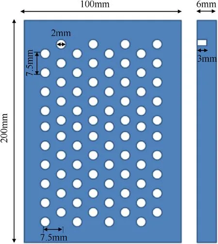
Fig. 1. Hole arrangement for incorporating filler material to manufacture surface composites.
Vickers hardness tester,operated at 100 g load for the dwell time of 10 s, was utilized to measure microhardness of the processed zones. Charpy impact test (ASTM E23) was carried out at room temperature to measure total absorbed energy to evaluate impact toughness of the specimens.The fractured surfaces of impact tests were observed using SEM operated in the secondary electron imaging mode.A pin on disc,DUCOM TR-20L,rotary tribometer was employed to investigate wear characteristics. A specimen holder was specially designed and fabricated to hold the specimen pin against the hardened steel disk(60 HRC).Polishing was carried out using 1200 grit emery paper and 3 μm diamond paste to prepare wear samples.All the tests were performed under 30 N nominal load at 1 m/s constant sliding speed for 600 m sliding distance. An electronic weighing scale having least count of 0.1 mg was utilized to measure mass difference which is used to calculate wear loss.
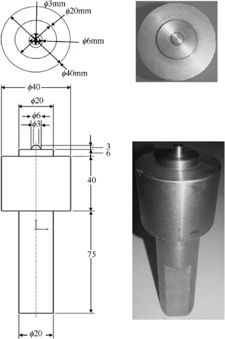
Fig. 2. W-La2O tool used in the experiment: Drawing and actual photograph.
3. Results and discussion
3.1. Microstructural analysis
Optical macrograph of the transverse cross section, revealing size of the SZ and TMAZ,for the FSPed sample is shown in Fig.3(a).The optical microstructure of base metal AA7075-T6,characterized by elongated grains in rolling direction along with irregular shaped second phase particles,is shown in Fig.3(b).FSP was conducted in the direction perpendicular to rolling direction.Fig.3(c) illustrates the basic microstructural feature of FSP showing three distinct microstructural regions viz. nugget zone (NZ), thermomechanically affected zone (TMAZ), and heat affected zone (HAZ).During FSP, both friction as well as plastic deformation is responsible for heat generation,which in turn causes microstructural and property changes. The nugget zone (NZ) undergoes dynamic recrystallization and very fine and equiaxed grains are observed in this zone. As a result of dynamic recrystallization amount of grain surface energy increases this in turn increase number of grain edges [31]. Owing to inadequate heat and plastic deformation,recrystallization does not take place in TMAZ. The general characteristic of this region is increased dislocation densities within the deformed and rotated grains. HAZ only experiences thermal cycle through diffusion heat transfer and a little grain growth and precipitate coarsening can be observed in this region[32].Dynamically recrystallized fine grained NZ of FSPed AA7075 without filler and with SiC filler is shown in Fig.3(d)and(e)respectively.Dynamically recrystallized,evenly distributed fine grains are evident in the NZ of specimen FSPed without filler material as shown in Fig. 3(d). It is said that,by increasing overlap ratio and no.of passes filler particles disperse more uniformly [33]. SiC particle rich and particle deficient areas in the form of partial and full onion ring pattern are clearly visible in the NZ (Fig. 3(e) and (f)) of specimen FSPed with SiC filler particles, when only single track FSP was performed without overlapping.Onion ring patterns having several concentric rings were observed in NZ of FSPed with SiC filler as shown in Fig. 3(f). No researcher has explained the particular cause of occurrence of these rings, although variation in grain size, particle density and texture has been suggested by few of them [31,32].Fig.3(g)shows the particle rich NZ of FSPed AA7075 with SiC filler reveling uniform dispersion of fragmented and non-fragmented SiC particles. Severe plastic strain generated by intense stirring action of pin and material flow during FSP resulted in fragmentation of most of the SiC particles and their homogeneous distribution into the Al matrix.
3.1.1. SiC particle distribution and precipitate evolution
With the intention of understanding the size and distribution of SiC particles in FSPed region and MgZn2precipitate evolution during post FSP ageing treatment the specimen were characterized using SEM and SEM micrographs are displayed in Fig.4.SEM image of as received AA7075-T6 is shown in Fig.4(a)reveals distribution of tiny MgZn2precipitates throughout the Al matrix.FSPed NZ SEM micrograph shown in Fig. 4(b) clearly depicts the fragmentation and uniform distribution of SiC reinforcement particles with good interfacial bonding with Al matrix.It was observed that precipitate dissolution has taken place during FSP which can be attributed to FSP induced annealing effect [34]. To recompense this softening effect post FSP artificial ageing was carried out at 120°C by varying time interval. SEM images shown in Fig. 4(c-e) illustrate the precipitate evolution during post FSP artificial ageing treatment. Precipitate evolution starts with formation of G-P zone which is metastable and coherent solute cluster of Mg, Zn and Cu. It then converts into semicoherent, discrete platelet particle called as η′(Mg(ZnCuAl)2). This further evolves into non-coherent, rod-like structure η(MgZn2)[19].After 18 h of ageing,tiny precipitates were observed in Al matrix along with very small fragmented SiC filler particles (confirmed by EDS) as shown in Fig. 4(c). It is also quite evident from Fig.4(c)that size of few fragmented SiC particles is in the nanometer range.With increase in ageing time(24 h)increase in the size of the precipitates was observed and with further ageing(30 h)coarsening of the precipitates took place as shown in Fig.4(d)and (e) respectively. High magnification SEM micrograph of BM AA7075 T6 illustrating size,shape and distribution of strengthening precipitates is shown in Fig. 4(f). Presence of second phase SiC particles changes the precipitation behaviour and kinetics of ageing[35]. Chuandong Wu et al. observed higher dislocation density in the vicinity of second phase particles, which in turn lead to heterogeneous nucleation process. Strain field associated with dislocations act as preferential nucleation sites and dislocation motion act as solute collector during precipitate evolution. It leads to formation of relatively smaller sized precipitates [36]. Small and coarse rod-like precipitates were observed in NZ as shown in Fig. 4(d-f). Their size, shape and distribution implies that they include fine Mg(ZnCuAl)2precipitates and Al7Cu2Fe coarse precipitates[19].Appearance of strong Al and C peaks in EDS analysis indicate that fragmented nano sized SiC particles attaches themselves to these precipitates.
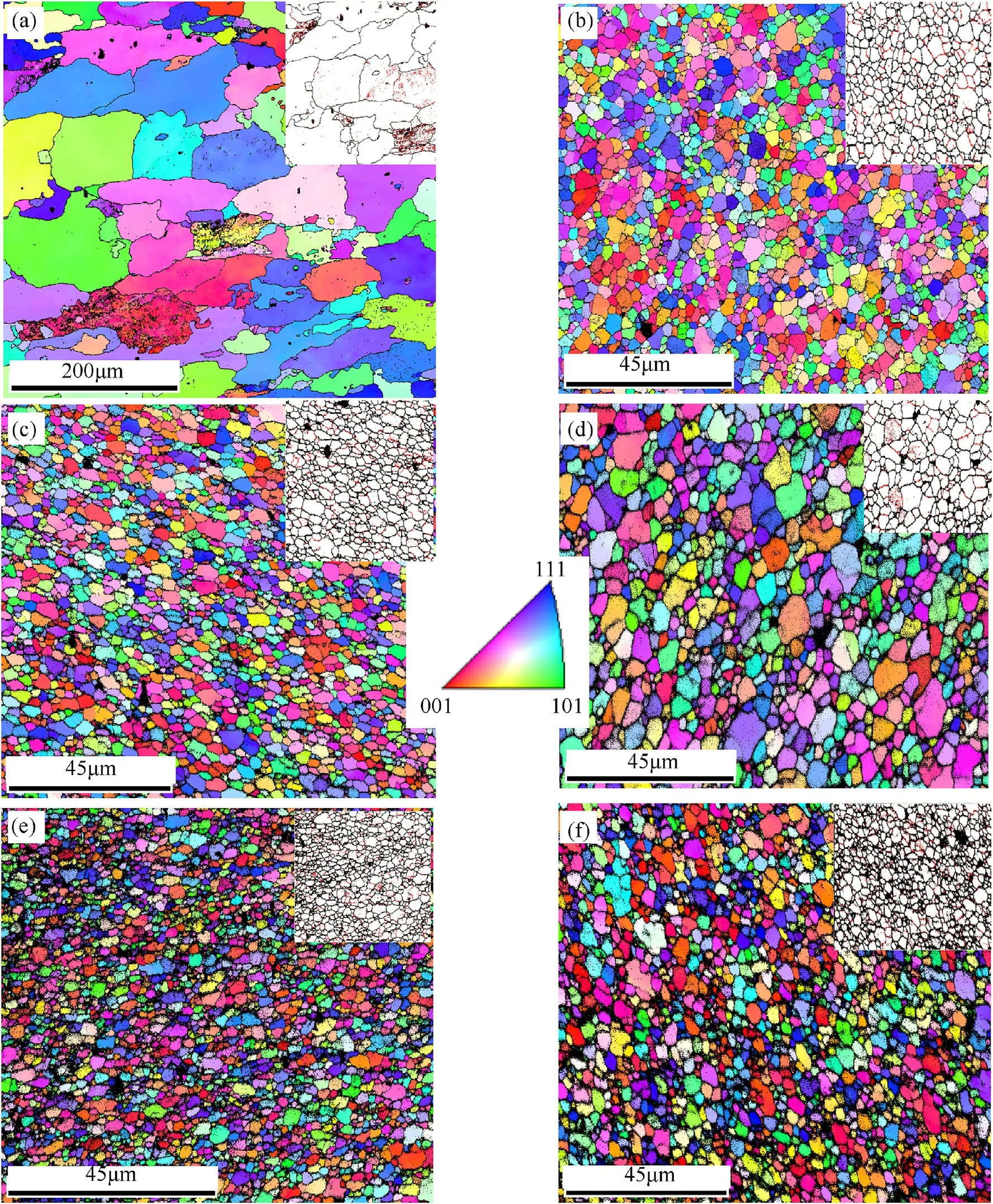
Fig.5. EBSD images(IPF maps)of(a)Base Metal AA7075-T6,NZ of FSPed AA 7075(b)without filler,(c)SiC filler,(d)NZ of post FSP without filler age hardened AA 7075 at 120 °C for 24 h, NZ of post FSP with SiC filler age hardened AA 7075 at 120 °C for (e) 12 h (f) 24 h.
3.1.2. Electron backscattered diffraction (EBSD)
Fig. 5 shows the Inverse Pole Figure (IPF) maps of before and after FSP AA7075. The high-angle grain boundaries (HAB) (>15°)and low-angle grain boundaries (LAB) (2-15°) are indicated using black and red colour in the maps, respectively (insight of Fig. 5(a-f)). In these maps, the black areas in the vicinity of grain boundaries are non index points, representing filler particles and complex intermetallic compounds.Fig.5(a),IPF map of base metal AA7075-T6,reveals microstructural heterogeneity in base material in the form of size and shape of the grains. Presence of LAB is also clearly visible in BM.The NZ IPF map of FSPed AA7075 without filler shown in Fig. 5(b) reveals that dynamic recrystallization led to formation of fine and equiaxed grains. It is considered that, the dislocations produced by severe plastic deformation during FSP are absorbed in subgrain boundaries. This increases misorientation of LAB and LAB transform into HAB by continuous dynamic recrystallization process producing fine microstructure [37]. Fig. 5(c)shows IPF map of SiC filler incorporated FSPed NZ demonstrating finer microstructure than that of FSPed without filler.Incorporation of SiC reinforcement during FSP generates additional thermomechanical effect leading to refinement of microstructure. IPF maps of specimen FSPed with and without SiC filler and then age hardened at 120°C are shown in Fig. 5(d-f).
It is quite evident from these maps that, notable grain growth was observed during artificial ageing treatment in the specimen FSPed without filler compared to the specimen FSPed with SiC filler.It is also supported by Fig.6(a)which depicts the effect of FSP with and without SiC filler and post FSP ageing times on average grain size calculated using EBSD. Continuous recrystallization/extended recovery could be the reason for slight grain growth during post FSP ageing treatment [38,39]. Second phase SiC particles incorporated as reinforcement plays an significant role in pinning the grain boundaries and does not allow them to migrate during post FSP ageing treatment(Zener pinning).Additional information,from the EBSD analysis,in the form of GOS and GAM,illustrating intra grain misorientations is shown in Fig. 6(b and c). It is observed that misorientation within the grain, which is directly related to dislocation density, initially increased after FSP. It further increased by adding SiC reinforcement and then decreased during subsequent age hardening treatment.
3.2. X-ray diffraction (effect of post FSP age hardening)
To reconfirm the presence of SiC filler in processed zone and understand precipitate evolution with respect to ageing times during post FSP ageing treatment, XRD analysis was carried out.Fig.7(a)shows the stack of XRD patterns of base metal AA7075-T6,FSPed AA7075 with and without filler and post FSP age hardened AA 7075 at varying time intervals.Five distinct peak patterns of the Al matrix are clearly visible corresponding to planes of(111),(200),(220),(311)and(222).The presence of SiC(JCPDS 49-1623)phase is evidently revealed in XRD results of the entire specimen incorporated with SiC filler. According to literature, MgZn2is the main precipitate in the NZ of AA7075 processed by friction stir welding,though there is possibility of finding complex intermetallics like Al2CuMg, Al2Mg3Zn3and Al2Cu [40]. Base metal and post process age hardened at various times specimen show peaks of the MgZn2(JCPDS:34-0457)phase.The peaks of MgZn2are found to be weak in the specimens having less ageing time,but become prominent as the time of ageing is increased.Absence of apparent peaks of MgZn2in FSPed without ageing condition indicates that during friction stir processing, precipitate evolution have not taken place. This is in agreement of few of the previous studies [34] but contradictory observations of precipitate evolution during FSP are also reported[19]. Variation in process parameters might be the reason behind these contradictory findings. Inset of Fig. 7(a) illustrates relative peak broadening and peak shift of (311) pole of BM AA7075 after FSP with SiC filler and subsequent artificial ageing treatment. Significant changes in peak widths and peak position(s)were observed after FSP and post FSP ageing treatment.Lattice strains and residual stresses are normally calculated by change in peak widths and position(s), respectively. In present study, residual stresses and lattice strains are calculated using (311) peak as high angle poles/peaks provide accurate measurements of lattice strains and residual stresses [41].
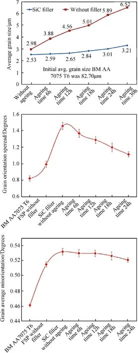
Fig. 6. Plots of average grain size, GOS and GAM by EBSD for different processing conditions. Standard deviation values, based on data from several scans, are also shown. (In Fig. 6(b) and (c), points 4 to 9 are all for FSP with SiC filler).
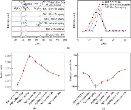
Fig.7. (a) XRD scans of intensity vs.2θ for different processing conditions. The positions of the primary Al, MgZn2 precipitate and SiC are indicated.The relative peak broadening and peak shift of(311)pole is shown in inset for different processing conditions,(b)Lattice strain(from Williamson-Hall plots)and(c)Residual stress(from sin2Ψ(XRD)method)for different processing conditions. Artificial ageing was carried out at 120 °C. (In Fig. 7(b) and (c), points 4 to 9 are all for FSP with SiC filler).
Effect of FSP, SiC filler and post FSP ageing treatment on lattice strains calculated using slopes of Williamson-Hall plots and residual stresses calculated using sin2Ψ method(Reusse’s model)are shown in Fig.7(b)and(c)respectively.It was quiet evident from the plots that generation of dislocations and grain refinement caused by severe plastic deformation during FSP and incorporation of SiC filler has noteworthy impact on development of lattice strains as well as residual stresses.There is increase in both lattice strains as well as compressive residual stresses due to FSP and incorporation of SiC filler. It is also interesting to note that, the generated lattice strains and residual stresses due to FSP and addition of SiC filler showed decreasing trend with increase in ageing time. It could be attributed to dislocation annihilation and thereby decrease in dislocation density called as recovery process.
3.3. Hardness
The average hardness (Hv0.1) of base metal AA 7075-T6, after solutionizing heat treatment and FSPed alloy under different conditions is presented in Fig. 8(a). The base metal hardness was 143 Hv. As the base metal was in T6 condition, solutionizing heat treatment was carried out for homogenizing and softening the alloy. After solutionizing heat treatment hardness of the alloy was dropped to 92 Hv because of dissolution of strengthening precipitates. There was only modest improvement in the hardness of the FSPed alloy without filler however substantial improvement in the hardness was observed in the FSPed alloy reinforced with SiC powders. In case of FSP without filler, increase in hardness was purely due to grain refinement and enhancement in dislocation density.During FSP,intense plastic strain generated by rotating pin and heat generated by friction,initially leads to mechanical rupture of inherent grain boundaries and then dynamic recrystallization producing very fine grains. Increase in grain boundary area enhances the hardness.Both,dispersion strengthening caused by SiC particles and grain refinement during FSP is responsible for improvement in the hardness of alloy FSPed with SiC filler. Inhomogeneous local deformation is produced by addition of SiC particles.This supports the breakup of the grains and thereby increases kinetics of recrystallization process.
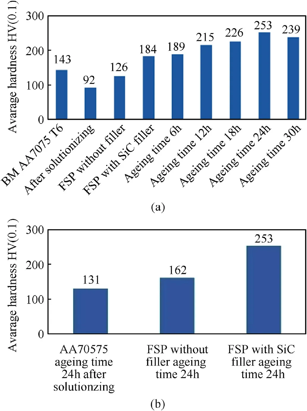
Fig. 8. (a) Average hardness (Hv0.1) observed in the variety of specimen during microhardness test showing effect of FSP, filler addition and post FSP ageing (carried out at 120 °C) time on hardness. (b) Average hardness comparison after 24 h age hardening (carried out at 120 °C) between AA7075 after solutionizing, FSP without filler and FSP with SiC filler. (In Fig. 8(a), points 4 to 9 are all for FSP with SiC filler).
SiC particles dispersed in the Al matrix during FSP also are responsible for grain boundary pinning (Zener Pinning). Fine SiC particles fragmented during FSP does allow grain boundaries to migrate. Finer grain structure was obtained by FSP with SiC filler particles compared to FSP without filler as a result of grain boundary pinning action produced by reinforced SiC particles which is clearly in agreement with the results obtained by EBSD(Figs. 5 and 6(a)). Fine non-shearable SiC particles dispersed in Al matrix hinder motion of dislocations.Dislocations can bypass only by making loops around these particles and in this process new dislocations are created(Orowan Mechanism).Thus,improvement in hardness during FSP with SiC particles can be attributed to combined effect of individual high hardness of SiC particles, grain refinement,Zener pinning and dispersion strengthening.
Post FSP artificial ageing shows considerable influence on hardness and nearly twofold increase in hardness was observed in FSPed AA7075 with SiC filler artificially aged at 120°C for 24 h compared to base metal AA7075-T6. A graph showing comparison of average surface microhardness between solutionized, FSPed without filler and FSPed with SiC filler AA7075 aged at 120°C for 24 h is shown in Fig.8(b).Microhardness of precipitation hardening Al alloys depends on size, shape, distribution and volume of strengthening precipitates. It was observed that, hardness increased initially with increase in ageing time up to 24 h but after that it decreased by further increase in ageing time. It is reported that, with increase in aging time some of the primary GP(I) zones are substituted by the higher stability GP(II) zones and fine η′precipitates thereby increasing microhardness [42]. At higher ageing times coarsening of precipitates takes place which reduces hardness.From the SEM micrographs(shown in Fig.4(d and e))and XRD results (shown in Fig. 7(a)), it can be interpreted that MgZn2precipitate evolution had taken place up to 24 h of ageing and after that precipitate coarsening had occurred which contributed to increase in hardness initially up to 24 h ageing and then drop in hardness with further increase in ageing time.
3.4. Wear
Effect of FSP with and without SiC reinforcement and post FSP age hardening (ageing time) on wear resistance in terms of wear loss is shown in Fig.9.Noteworthy improvement in wear resistance was observed in FSPed AA7075 with SiC filler.Incorporation of SiC particles in the Al matrix alters the wear mechanism.It is reported that, during Pin on Disc wear testing, direct load between the surface of wear specimen and counter disc is reduced owing to load bearing capacity of the hard carbide particles reducing wear loss appreciably[43].As a consequence of carbide particles,material is removed from the softer matrix selectively. This soft material acts as lubricant by occupying the intermediate position between pin and disc. Wear resistance of FSPed AA7075 with SiC filler further increased after age hardening, carried out at 120°C, up to 24 h ageing because of evolution of evenly distributed, tiny, hard and wear resistant intermetallic compounds (precipitates). A drop in wear resistance was observed once ageing time crosses 24 h, as a result of coarsening of precipitates. Evenly dispersed, hard and wear resistant SiC particles reinforced during FSP along with tiny MgZn2precipitates evolved during age hardening are the chief contributors in enhancing wear resistance of AA7075.
3.5. Impact toughness
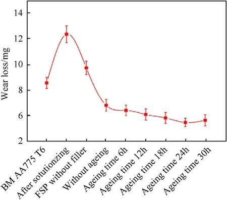
Fig. 9. Wear Loss during pin on disc wear test carried out with Load 30 N, Sliding Distance 600 m,Sliding speed 1 m/s for various processing conditions(Points 4 to 9 are all for FSP with SiC filler).
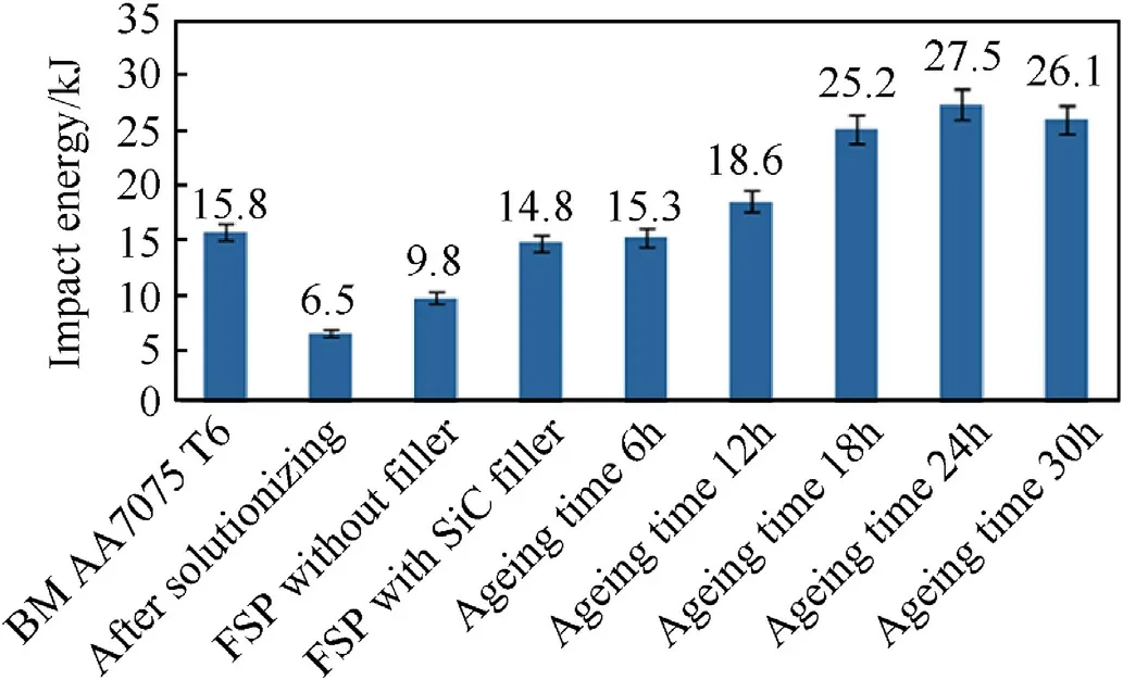
Fig. 10. Impact energy absorbed (KJ) by the variety of specimen during Charpy test illustrating effect of FSP, filler addition and post FSP ageing treatment on impact toughness. (Points 4 to 9 are all for FSP with SiC filler).
Materials capability of absorbing rapidly applied forces is very much in demand for structural applications so as to prevent costly complications. Room temperature Charpy impact test was performed to measure absorbed energy up to fracture and consequence of FSP with and without SiC filler along with post FSP age hardening on impact toughness is presented in Fig. 10. All the samples for the Charpy impact test were taken from the nugget zone.BM AA7075-T6 possessed moderate impact toughness which dropped by solutionizing heat treatment due to dissolution of strengthening precipitates which obstruct crack propagation.FSPed AA 7075 without filler showed modest improvement in absorbed impact energy owing to grain refinement occurring during FSP by dynamic recrystallization process. Grain boundaries provide resistance crack propagation, as nature of fracture during impact testing is generally transgranular. It is noteworthy that,FSPed AA7075 with SiC filler showed significant improvement in impact toughness by absorbing good amount of energy up to fracture. Most of the SiC particles had been fragmented into tiny and small sized particles by high strain rate friction and got distributed homogeneously throughout the matrix by stirring action associated to FSP.It was also observed that they are having very good interfacial bonding with the matrix. These, hard and non shearable SiC reinforced particles might have hindered the process of crack initiation and propagation leading to increase in impact toughness value. Similar results were obtained by M. Refat et al.using nano alumina powder as reinforcement during FSP [19].
Post FSP artificial ageing treatment was carried at 120°C by varying time and its influence on impact toughness is depicted in Fig.10.Amount of absorbed energy went on increasing up to 24 h of ageing and thereafter it diminished slightly by further increase in ageing time, which is similar to the trend shown by hardness of processed specimen. Continued evolution of tiny, hard and crack resisting MgZn2precipitates up to 24 h and precipitate coarsening occurred after that might be the reason for that. Overall, it can be inferred that grain refinement caused by FSP, grain boundary pinning by SiC particles and resistance to crack propagation by SiC reinforcement and MgZn2precipitate play a key role in improving impact toughness.
3.6. Fractography
In order to investigate the mode of fracture and to identify the effect of SiC reinforcement during FSP and post FSP artificial ageing treatment on the mode of failure of AA7075 SEM fractography study of impact test fracture surfaces was carried out and shown in Fig.11(a-d). It is reported that, toughness anisotropy influencing impact fracture arises through three basic factors viz. microstructural anisotropy in the form of banding or elongated grain structure, non-uniform distribution in the size and shape of intermetallics and crystallographic texture [44,45]. Shear-type morphology without fine dimples can be observed on the fractured surface of base metal AA7075-T6 before FSP as shown in Fig. 11(a). It also shows large size voids and fractured valleys in consequence of the coarse grained microstructure of base metal.Fracture surface morphology, shown in Fig. 11(b and c), changed significantly after FSP with and without SiC filler. Presence of uniformly distributed,fine dimples of varying size and shape over the surface clearly indicate ductile failure due to the fine grained microstructure validating relatively high toughness value after FSP.Fig. 3(c) shows existence of few SiC particles on the fractured surface which invariably provide hindrance to crack propagation and increase absorbed impact energy.Appearance of very fine and deep dimples on the fractured surface of post FSP age hardened AA7075 with SiC filler (Fig. 10(d)) illustrates the influence of uniformly distributed MgZn2precipitates on crack propagation during impact fracture.
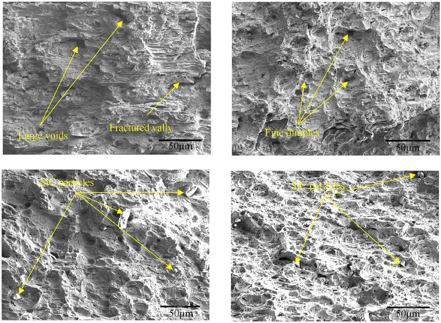
Fig.11. SEM Micrographs showing fractured surfaces of (a) BM AA7075-T6, (b) FSPed AA 7075 without filler, (c) FSPed AA 7075 using SiC filler, (d) Post FSP using SiC filler age hardened at 120 °C for 24 h.
4. Conclusion
In the present study, FSP was carried out on AA 7075 with and without micro-sized SiC filler powders achieving uniform dispersion of reinforced particles.The core objective was to examine the influence of FSP,incorporation of SiC reinforcement during FSP and post FSP artificial age hardening on the microstructure,mechanical properties and impact fracture of the processed area.Based on the experimental observation and analysis, the following conclusions are drawn:
1. FSP with and without SiC reinforcement lead to severe grain refinement. SiC particles were fragmented by the mechanical stirring action exerted by the pin and distributed uniformly in the Al matrix on account of material flow showing good interfacial bonding. Grain boundary pinning action exercised by SiC particles during dynamic recrystallization process caused more prominent grain refinement.
2. Significant increase in the microhardness,impact toughness and wear resistance was observed by the addition of SiC filler powders. Post process age hardening lead to further improvement in these properties. Combined effect of grain refinement,Zener pinning, dispersion hardening and precipitation hardening brought about nearly twofold increase in mechanical properties.
3. Post FSP artificial ageing time has strong influence on precipitate evolution and their coarsening.
4. Ductile fracture mode becomes more effective under impact loading after grain refinement by FSP leading to decrease in dimple size and increase in amount of the dimples on the fractured surface.
Acknowledgements
The authors would like to acknowledge National Facility for Texture and OIM (A DST-IRPHA project), IIT Mumbai for XRD and EBSD measurements. One of the authors VDH would like to acknowledge Science and Engineering Research Board (SERB) for financial assistance (EEQ/2016/000422) to carry out project work.
杂志排行
Defence Technology的其它文章
- Analysis of the stress wave and rarefaction wave produced by hypervelocity impact of sphere onto thin plate
- Effect of bending temperatures on the microstructure and springback of a TRIP steel sheet
- Dynamic parameters of multi-cabin protective structure subjected to low-impact load - Numerical and experimental investigations
- An eikonal equation based path planning method using polygon decomposition and curve evolution
- Influence of active constrained layer damping on the coupled vibration response of functionally graded magneto-electro-elastic plates with skewed edges
- Crashworthiness performance of hybrid kenaf/glass fiber reinforced epoxy tube on winding orientation effect under quasi-static compression load
