Effect of bending temperatures on the microstructure and springback of a TRIP steel sheet
2020-10-27NatthasakPornputsiriKannachaiKanlayasiri
Natthasak Pornputsiri, Kannachai Kanlayasiri
Industrial Engineering, Faculty of Engineering, King Mongkut’s Institute of Technology Ladkrabang, Bangkok,10520, Thailand
Keywords:
ABSTRACT Transformation-induced plasticity (TRIP) steel possesses high strength and formability,enabling the use of a thinner gauge material and allowing for the fabrication of complex shapes. In this research, we measured the effect of bending temperatures on the microstructure and air-bending springback angle of TRIP steel at temperatures from 25 to 600 °C. Real-time in situ X-ray diffraction and scanning electron microscopy were used for pre-and postbending analysis.As the prebending temperature increased from 25 °C to 600 °C,the retained austenite(RA)volume fraction decreased,and the RA transformed to bainite at temperatures above 400 °C. The springback angle was positively correlated with the prebending RA volume fraction, with the smallest springback angle achieved at 400 °C. Additionally, the springback angle was positively correlated with the bending angle,because the RA transformation ratio contributed to increased strain hardening.Further microstructure analysis revealed that the RA became elongated in the tension direction as the bending temperatures increased.
1. Introduction
Autobody metal sheets require high strength and formability.A high-strength sheet enables the use of a thinner gauge material,which further allows light weight and fuel efficiency [1]. Meanwhile, material formability allows for the fabrication of complex shapes. Transformation-induced plasticity (TRIP) steel possesses both characteristics [2]. TRIP steel has generally been shown to have a tensile strength of 600-1000 MPa and an elongation of 20-25% [3].
The high strength and formability of TRIP steel are largely attributed to the complex microstructure, consisting of retained austenite and bainite in the ferrite matrix [4]. Furthermore, the retained austenite is transformed to martensite upon deformation,contributing to increased strain hardening [5].Nevertheless, highstrength steel is often affected by bending springback. The springback affects the mechanical properties, metal sheet thickness, bending radius and forming temperature [6]. The existing research on advanced high-strength steel (AHSS) focused on the effect of a thermal treatment on the microstructure and springback[7-10] and failure mechanisms [11].
A variation in the deformation temperatures impacts the mechanical properties of TRIP steel and, in turn, the springback behavior. For AHSS and TRIP and twinning-induced plasticity(TWIP) steels, the yield strength, ultimate tensile strength and strain hardening reduced at elevated deformation temperatures(25-600°C) [12,13]. The highest strength was achieved at 25°C and steadily decreased with increased deformation temperatures.Meanwhile,the total elongation decreased between 25 and 400°C and increased between 400 and 600°C.In addition,the springback behavior was governed by the phase dislocation and mechanically induced phase transformation [14,15].
The springback angles for TRIP steel sheets decreased when the hot and warm forming temperatures were above 457°C [16], the recrystallization temperature of ferrite. The V-bending springback angle in TRIP steel was positively correlated with the retained austenite volume fraction and bending temperatures [17]. In essence, at forming temperatures of 400-450°C, the springback angle was significantly reduced as the ferrite recrystallized. Nonetheless, the springback behavior and microstructure analysis in previous work followed cooling(at room temperature)rather than with real-time in situ analysis. On the other hand, Allain et al.[18-20] used in situ X-ray diffraction to characterize the microstructure evolution of AHSS and other steels during thermal treatment and air-cooling.
We investigated, in real time, the phase transformation during heating for pre- and postbending and the effect of the bending temperatures on the microstructure evolution and air-bending springback angles of TRIP780 steel. Real-time in situ X-ray diffraction (XRD) and scanning electron microscopy (SEM) were used to characterize the pre- and postbending microstructures of the steel at 25, 200, 400, and 600°C. Our results revealed the continuous phase transformation during prebending heating and the postbending phase transformation of TRIP steels shown by the real-time XRD technique for springback control of TRIP steel by choosing the optimal bending temperature.
2. Experimental procedure
2.1. Material preparation
In this research,the base metal was TRIP780-grade AHSS sheet with a thickness(t)of 1 mm and chemical composition of 0.107 wt%C,1.39 wt%Mn,0.952 wt%Si,0.024 wt%Al,0.031 wt%Cr,0.014 wt%Cu and 0.0246 wt%P. Table 1 lists the tensile properties in the transverse direction of the experimental steel at room temperature(25°C)based on the ASTM E8 standard,obtained using a universal tensile testing machine.The bending specimens had dimensions of 12 × 30 × 1.0 mm (W × L × t).
Fig.1 shows the thermal cycle used to obtain the typical TRIP steel microstructure[22].TRIP steel is produced by heating steel to the annealing temperature so that the dissolution of cementite occurs and the formation of austenite starts to produce a microstructure consisting of austenite distributed in a matrix of ferrite.The holding time and temperature determine the proportion of each phase.The temperature for annealing was set at 770-850°C.Then, the steel was cooled quickly to 400°C and held at this temperature. During cooling and holding, part of the intercritical austenite transformed to B. Later, after cooling to room temperature, the final microstructure consisted of F, containing the RA dispersed into B.
2.2. Experimental bending temperatures
The warm-bending temperatures were varied between 25 and 600°C,given a bending rate of 60 mm·min-1.Prior to the air-bend loading, the steel specimens (initial temperature of 25°C) were thermally treated in an electrical furnace at 2°C· min-1to the target temperatures (200, 400, and 600°C) and were retained in the furnace for another 5 min upon reaching the target temperatures, so that the unstable retained austenite phase was transformed into the bainite and ferrite phase[17].A thermocouple was placed close to the specimens for temperature regulation[23].Fig.2 illustrates the prebending thermal treatment of the experimental specimens, and Table 2 lists the experimental parameters.
2.3. Air-bending experiment and microstructure analysis
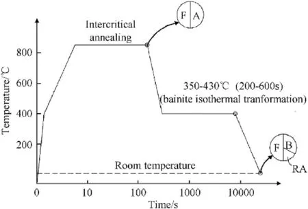
Fig.1. Thermal cycle used to obtain the TRIP microstructure.
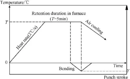
Fig. 2. Prebending thermal treatment of the TRIP780 specimens.

Table 2Experimental parameters.
The air-bending experimental setup followed the ISO 7438:2010 standard (Fig. 3). The sample was bent at various angles (15°, 30°,45°, 60°, and 75°) for each of the four bending temperatures (25,200, 400 and 600°C), and while bending, the temperature of the test specimen was maintained at the required temperature by an induction heating system. The radius of the punch (Rp) was 0.25 mm, and the roller (Rd) was 10 mm. The springback behavior and microstructure of the postbending steel specimens were subsequently determined.The bending angle was manipulated by the punch penetration, controlled by a Zwick Z20 universal testing machine, at a bending rate of 60 mm·min-1.
The springback angles (Δθ) were determined by optical microscopy,and the bending angle(θ)was compared with the unbending angle (θ′) using CAD software. Fig. 4 shows the method used to measure the springback angle in the air-bending test.The standard method of measuring the springback angle used three point references (at the center and both ends) on the cross-section of the specimen(V-shape).If the center point is the vertex,the two linescan be connected.The two resulting lines function as baselines,and the work angle can be determined using these two lines. The springback angle is the bending angle θ minus the unbending angle θ’ (Δθ =θ -θ’).

Table 1Tensile properties of the TRIP780-grade AHSS sheet at room temperature[21].
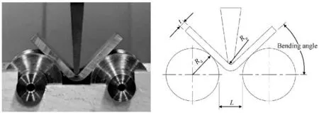
Fig. 3. Photograph and diagram of the air-bending experiment.
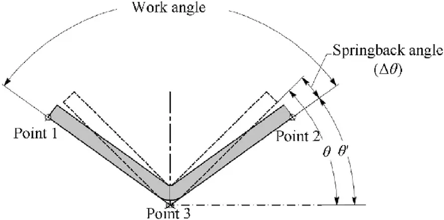
Fig. 4. Method of springback angle measurement.
The pre- and postbending phase transformations at various bending temperatures were determined at 200, 400 and 600°C using real-time in situ X-ray diffraction (XRD, Rigaku, D/Max-RB)with Cu Kα radiation. The volume fraction of retained austenite(Vγ)was calculated using the integrated intensities(I)of the(200)α and (211)α peaks of the BCC structure and the (200)γ, (220)γ and(311)γpeaks of the FCC structure following[24]:

where Vγ is the volume fraction of retained austenite, Iγ is the intensity of retained austenite,Iα is the intensity of ferrite and R is the calculated theoretical intensity [24].
The microstructures of the pre- and postbending steel specimens were characterized by scanning electron microscopy (SEM,JEOL, JSM-6510 LV); the specimens were mechanically polished using a conventional method,and the samples were cut into crosssections, hot mounted, and polished. Additionally, the samples were polished with 0.1 μm alumina powder and Lepera etchant[18]. In the SEM micrographs, retained austenite (RA), bainite (B),and ferrite (F) are represented by white, gray, and black colors,respectively[25].
3. Results and discussion
3.1. Microstructure of the experimental steel
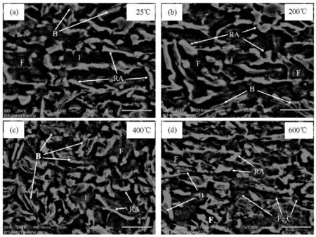
Fig. 5. SEM micrographs of the prebending TRIP780 specimens at the indicated temperatures.
Fig. 5(a)-(d) illustrate the microstructure of the prebending TRIP780 steel specimens (after air-cooling) treated at 25, 200, 400 and 600°C. In general, the surface of the F was the roughest, as it was etched more deeply than the other phases. The surface of bainite (B) was smoother, and carbide had smaller particles, while the surface of retained austenite (RA) was smooth [26]. The microstructure of TRIP steel without heating (25°C) is shown in Fig.5(a);the microstructure consists of RA,and B was embedded in the F matrix. The microstructures of the samples heated at 200-600°C and held for 5 min are shown in Fig. 5(b)-(d). The microstructure of the sample, after 5 min at 200°C (Fig. 5(b)),mainly consists of RA and B embedded in the F matrix,which differs slightly from that of the unheated sample. As the bending temperature increased, RA transformed into B and carbides. Once the bending temperature reached 400°C, the microstructure of the TRIP steel sample clearly differed from that of the unheated sample.Fig. 5(c) shows that the microstructure of the sample heated at 400°C predominately consisted of F and B, with some RA islands embedded in the F matrix. When the bending temperature increased to 600°C,the RA phase decreased to a minimum,and the carbide(Fe3C)was embedded in the F matrix,as shown in Fig.5(d).In the SEM analysis, RA is shown in white, B is shown in gray,carbide is shown in fine particle white, and F is shown in black.
3.2. Phase transformation
3.2.1. Phase transformations during isothermal processing
Prebending phase transformation at various bending temperatures, where diffraction peaks indicate phase transformations.The RA peaks at (111)γ, (200)γ, (220)γ, and (311)γ and the F peaks at(110)α,(200)α and(211)α,were assigned following Yu et al.[13]and Sugimoto et al.[27].The volume fraction of RA at each temperature was calculated using Equation (1), and the carbon contents in RA were measured using the lattice parameter and empirical equation[28], expressed as:where aγ is the austenite lattice parameter(Å)[29],Cγ is the weight percent of the carbon atom, and [C%], [Mn%], [Si%] and [Al%]represent the concentrations in weight fractions of carbon, manganese, silicon and aluminum, respectively. For convenience, the contents of the alloying elements in RA were assumed to be equivalent to the nominal steel composition for all bending temperatures.

A phase transformation in TRIP steel before bending can be evidenced by the dramatic changes in the diffraction patterns in Fig. 6. The disappearance and appearance of diffraction peaks are typical indicators of phase transformations.The diffraction pattern constitutes a mixture of the α pattern that reflects the matrix of F and B, which is hard to distinguish by X-ray diffraction due to its similarity with the diffraction pattern from the body-centered cubic(BCC)structure,whereas the γ pattern is derived from retained austenite(RA).Combining Figs.6 and 7(a),it may be noted that the bending temperature has a significant influence on the RA volume fraction. The RA volume decreased obviously as the temperature increased: this behavior was also observed by Yu et al. [13] and Tang et al. [30]. The volume fraction of RA decreased slightly from 15.11 to 14.14%as the temperature increased from 25 to 200°C and was similar to that in the microstructure images of TRIP steel without heating (25°C), as shown in Fig. 5(a) and b. Since the holding time was relatively short, a noticeable structural change did not occur. The relationship between the bending temperature and the average carbon content in the RA is shown in Fig.7b;the RA carbon content increased slightly as the temperature increased from 25 to 200°C. The increased RA carbon content was mainly caused by the carbon diffusion of F into the RA during heating[31].It should be noted that carbon diffused into the RA as the temperature increased, leading to more stable RA. Interestingly, the diffraction patterns changed significantly, the γ pattern peaks rapidly decreased from 14.14 to 4.24%, and the carbon content continuously decreased with increasing bending temperature from 200 to 400°C.Therefore,more carbon diffused from RA and mainly caused the decomposition of RA into B, including fine carbide(Fe3C), as shown in Fig. 5(c), which was consistent with the observations of Anazadeh et al.[32].When the bending temperature was in the range of 400-600°C, the γ pattern peaks nearly disappeared, while the α pattern peaks grew and the RA carbon content decreased slightly, indicating that the steel consisted of pure ferrite during holding in this temperature region. This indicated a TRIP steel phase transformation at 600°C, at which the microstructure consisted of F,pearlite(F+Fe3C)and little RA,as shown in Fig. 5(d).
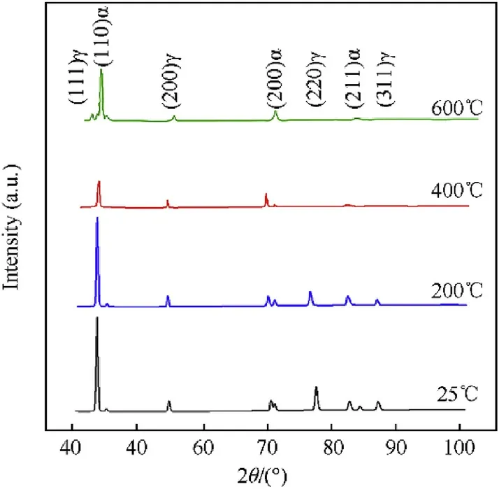
Fig. 6. Prebending real-time in situ XRD at different bending temperatures.
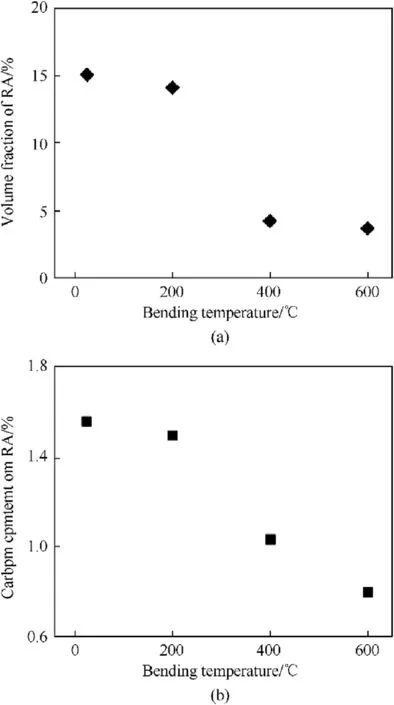
Fig. 7. Prebending: (a) volume fraction of RA and (b) carbon content in RA.
3.2.2. Phase transformation during deformation
A phase transformation during a deformation or the TRIP effect is the main reason for the improved ductility and formability.Fig.8 shows the postbending diffraction pattern by in situ XRD.Fig.9(a)presents the RA volume fraction after bending.With a 45°bending angle, the RA volume fraction decreased to ~15 vol% at 25°C and continuously decreased with increasing bending temperature; the RA fraction decreased to a minimum of~2 vol%at 600°C.Fig.9(b)shows the variation in the carbon content in the RA phase (postbending)with the bending temperature:it is clear that the bending temperature and plastic deformation affected the carbon content.The carbon content in the RA phase increased after bending and then decreased as the bending temperature increased. Note that this evolution of the carbon content was also observed by Shen et al.[33],where the average RA carbon content decreased with the RA volume fraction, following the higher bending temperature. A low carbon content reduces the stability of retained austenite[34].
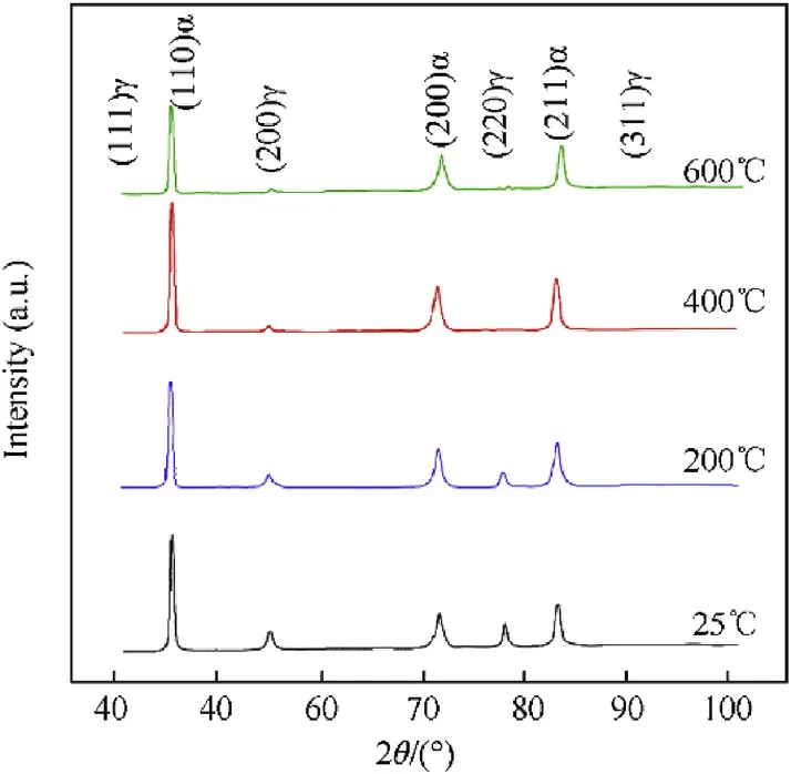
Fig.8. XRD patterns with post-bending of 45° at different temperatures for TRIP steel.
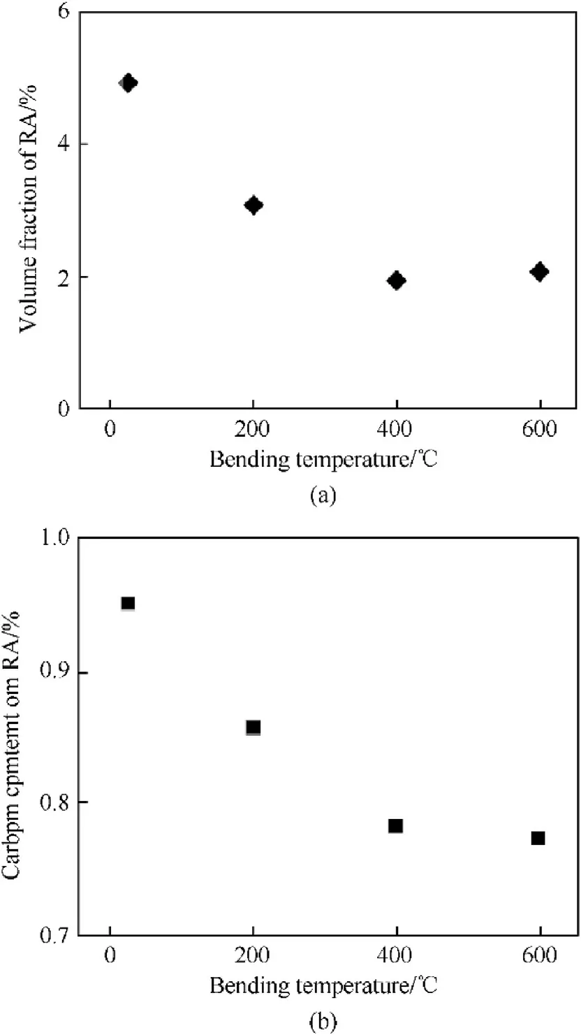
Fig. 9. Postbending of 45°: (a) volume fraction of RA and (b) carbon content in RA.
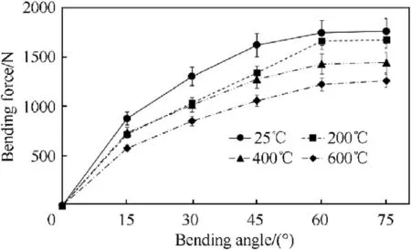
Fig.10. Bending angle - bending load relationships.
3.3. Bending load and the springback angle
Fig.10 shows the bending load versus the bending angle during air-bending for temperatures from 25 to 600°C.It can be seen that the bending load increased with increasing bending angle. It is understood that the bending force is a function of the plastic deformation volume and strain hardening.Meanwhile,the bending load decreased slightly with increasing bending temperature.These results correspond with the tensile test using different temperatures, and at higher testing temperatures, both the yield stress and ultimate tensile stress values decreased [35].
Fig. 11 illustrates the effect of the bending angle and bending temperature on the springback angle of the steel specimens.From this figure, we can understand how temperature affects the springback angle. This material exhibited lower springback at 400°C.In contrast,the material showed higher springback at a low bending temperature (25°C). The springback angles were positively correlated with the bending angles. Increasing the bending angle caused an increase in the springback angle. The springback was very low at a 15°bending angle and began to increase for higher strains up to a 75°bending angle. Increasing the bending angle increased the stretching in the material and consequently extended the region of the plastic deformation.Therefore,it can be understood that the RA phase transformation,strain hardening and springback angle increased as the plastic strain or bending angle increased.
The air-bending springback angle for thin steel sheet can be calculated from Ref. [36]:

where θ is the bending angle, Δθ is the springback angle, K is the ultimate tensile strength, ρ is the neutral axial position, ν is Poisson’s ratio, w is the die gap, E is Young’s modulus, and t is the thickness.
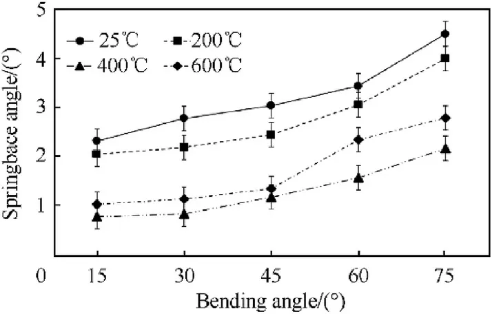
Fig.11. Effect of the bending temperature and angle on the springback angle.
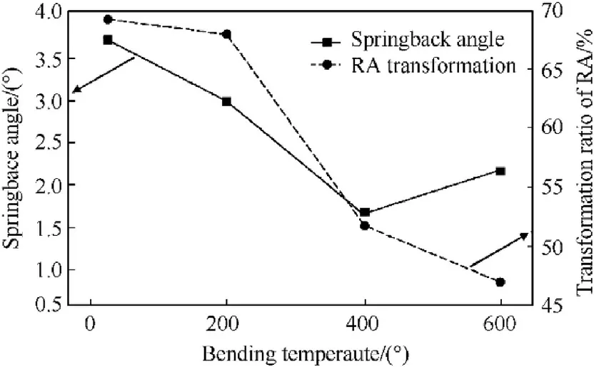
Fig.12. Transformation ratio of RA and springback angle vs the bending temperatures for a 45° bending angle.
In the air-bending experiment,the specimens were individually placed on cylindrical mandrels and pressed by a punch. Increased punch penetration depths increased the bending angles and the plastic deformation, contributing to increased springback angles.
It can be seen that the springback angles and bending temperatures were inversely correlated.This reduction can also be seen in the relation between the springback angle and phase transformation (see Fig.12).
The RA volume fraction after bending was investigated by XRD.It is obvious that the RA peaks decreased to a minimum after air bending,indicating that the RA decomposed during the test.The RA was transformed to martensite (M) during bending and thus increased the plasticity of the steel,which is the TRIP effect[37,38].Additionally,the appearance of the microstructure composition,as shown in Fig.13(a)and(b),and the XRD result confirmed the TRIP effect. Meyer and Vanderschueren [39] reported that the transformation of RA to the M phase, after forming, affected the (200)α and (211)α peaks, which increased with increasing deformation,corresponding to the XRD postbending shown in Fig.14.
Fig.15 illustrates the transformation ratio of RA by comparing the volume fraction with pre-and post-bending and the springback angles for bending temperatures from 25 to 600°C. A higher springback angle was observed with low bending temperatures(25 and 200°C) due to the higher transformation ratio of RA to M during the plastic deformation by bending or the TRIP effect and higher strain hardening [40]. After 5 min at 200°C, no noticeable structural changes occurred, similar to the case for the microstructure without heating (25°C), as seen from the timetemperature-transformation (TTT) diagram [41] in Fig. 15. In this temperature range, below the transformation temperature for RA to B, the holding time was relatively short. The springback angle rapidly decreased to a minimal value as the bending temperature increased to 400°C, which corresponded to the RA phase transformation ratio.The RA phase transformation ratio-approximately 60% at 25°C - decreased to approximately 40% at 400°C. At the same time, at a bending temperature of 400°C, more carbon diffused from RA and caused the decomposition of RA into B,indicating that the material was weakened in this temperature range[42,43].
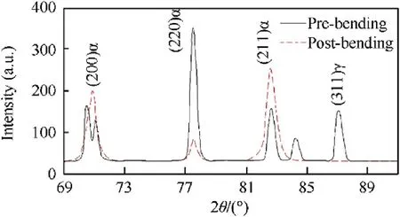
Fig.14. XRD patterns with pre- and postbending of 45° at a bending temperature of 25 °C.
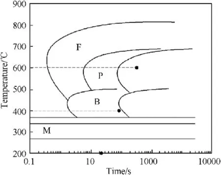
Fig.15. TTT diagrams of TRIP steel (CMnSiAlCr), calculated in JMatPro [41].
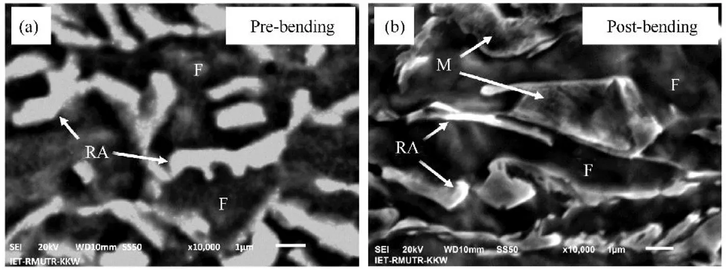
Fig.13. TRIP steel microstructure at bending temperature of 25 °C and bending angle of 45°.
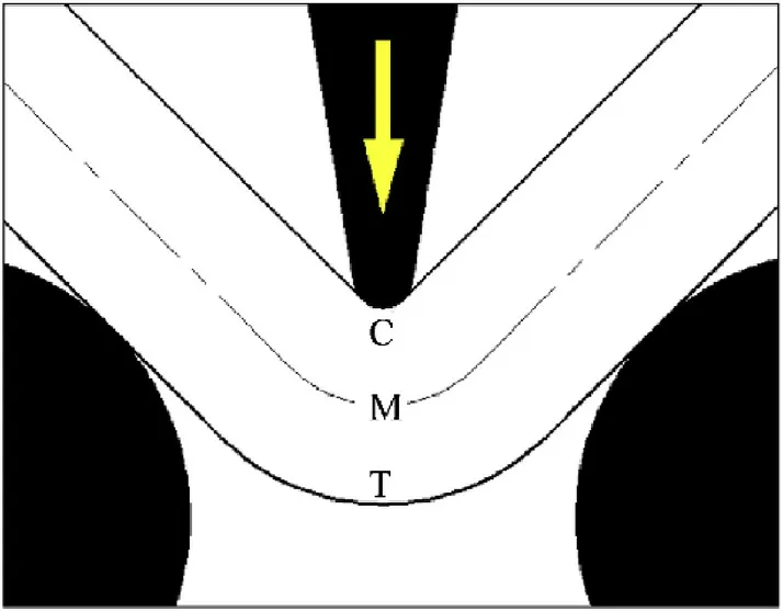
Fig.16. Cross-section of a steel specimen for a 45° bending angle.
This finding contradicts a conventional notion that the springback phenomenon increases with the bending temperature to 600°C, because the material yield stress increased due to the increase in carbide or cementite(Fe3C)in ferrite,leading to a higher yield strength [29,30]. Furthermore, a large amount of carbide(Fe3C) precipitated with heating at 600°C, which increased the yield strength [29,31] and, in turn, increased the springback.
3.4. Microstructure evolution
This section discusses the effect of the bending temperatures and bending angles on the cross-sectional microstructure of the steel specimens,as observed by SEM.Fig.16 shows a diagram of the cross-section of a steel specimen for a 45°bending angle,where C and T denote the sections that are subjected to compressive stress and tensile stress, respectively, and M is the midpoint, which is minimally affected by bending. The bending temperatures were varied between 25 and 600°C.In Fig.16,the T region was the target region of the microstructure evolution analysis, due to the relatively extensive phase deformation.
Fig. 17(a)-(d) show the bending cross-section microstructure evolution at the target region(T region)at bending temperatures of 25,200,400 and 600°C for a 45°bending angle.In Fig.17(a)and(b),with postbending at 25°C and 200°C,the microstructure showed that there was a high fraction of the rough surface of martensite as a result of the phase transformation from RA to M during the plastic deformation by bending,and the RA phase became elongated in the tension direction.In Fig.17(c),with postbending at 400°C,i.e.,the temperature ranges of the bainite transformation, the microstructure showed the B phase, and the RA phase was elongated in the tension direction. When the bending temperature increased to 600°C,the microstructure consisted of carbide(Fe3C)dispersed in the F matrix, and the RA phase decreased, as shown in Fig.17(d).
4. Conclusion
We investigated the effect of variable bending temperatures from 25 to 600°C on the pre-and postbending microstructures and air-bending springback angles of a TRIP780 steel sheet. The microstructure analysis used real-time in situ XRD and SEM observations. With prebending at 25°C and 200°C, the SEM images showed RA and B embedded in the F matrix; however, at 400°C,the RA rapidly transformed into F and fine bainite and then, at 600°C, transformed into F and pearlite (F+Fe3C), as shown in the XRD spectrum. The RA volume fraction decreased with increasing bending temperature. Furthermore, the pre- and postbending microstructures showed that the RA phase transformation ratio decreased with increasing bending temperature (from ~60% at 25°C to ~40% at 600°C). At the same time, the springback angle was positively correlated with the RA phase transformation ratio,and the smallest springback angle was achieved at 400°C. In addition, the springback angle and bending angle were positively correlated. This result was attributed to the amount of phase transformation and strain hardening.Moreover,the microstructure evolution analysis indicated that the RA became elongated in the tension direction as the bending temperatures increased.
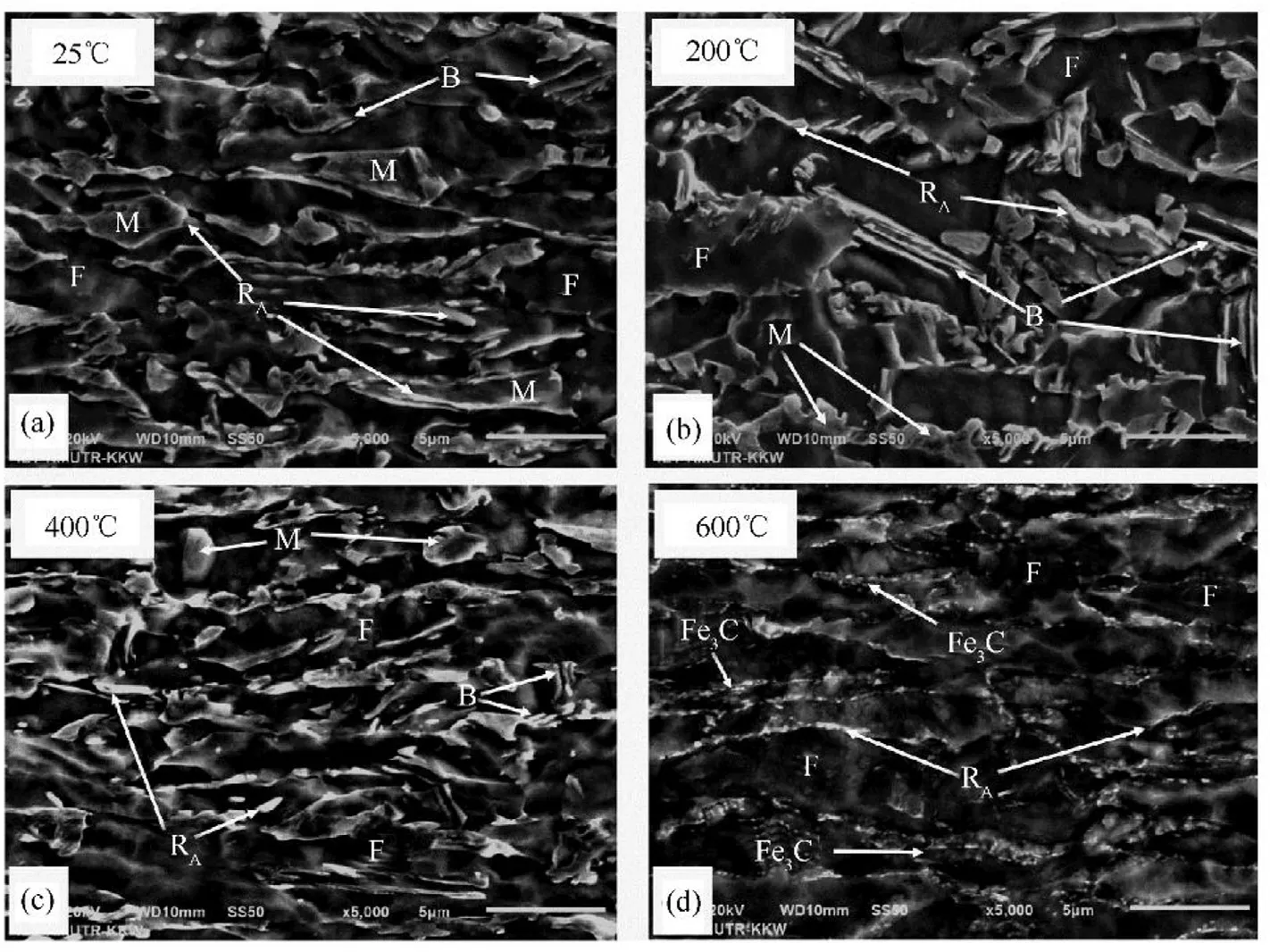
Fig.17. Microstructure evolution in the T region for various temperatures.
Declaration of competing interest
The authors declare no conflict of interest.
Acknowledgments
This research was funded by Faculty of Engineering, King Mongkut’s Institute of Technology Ladkrabang.
杂志排行
Defence Technology的其它文章
- Analysis of the stress wave and rarefaction wave produced by hypervelocity impact of sphere onto thin plate
- Dynamic parameters of multi-cabin protective structure subjected to low-impact load - Numerical and experimental investigations
- An eikonal equation based path planning method using polygon decomposition and curve evolution
- Influence of active constrained layer damping on the coupled vibration response of functionally graded magneto-electro-elastic plates with skewed edges
- Consequence of reinforced SiC particles and post process artificial ageing on microstructure and mechanical properties of friction stir processed AA7075
- Crashworthiness performance of hybrid kenaf/glass fiber reinforced epoxy tube on winding orientation effect under quasi-static compression load
