Performance Investigation on Elevation Cascaded Digital Beamforming for Multidimensional Waveform Encoding SAR Imaging
2020-10-24HEFengZHANGYongshengSUNZaoyuJINGuanghuDONGZhen
HE Feng ZHANG Yongsheng SUN Zaoyu JIN Guanghu DONG Zhen
(College of Electronic Science and Technology, National University of Defense Technology, Changsha410073, China)
Abstract:An important issue in a Synthetic Aperture Radar (SAR) system employing Multidimensional Waveform Encoding (MWE) is the fulfillments of Digital BeamForming (DBF) on receive in elevation for a reliable separation of the mutually overlapped echoes from multiple transmit waveforms.In this paper,the performance of a separation approach employing hybrid DBF in elevation by combining the onboard real-time beamsteering and a posteriori null-steering DBF on the ground is elaborately investigated.As a cascaded structure which comprises two subsequent DBF networks,the onboard part effectuates the steering of the mainlobes within multiple partitioned groups of antenna elements to ensure sufficient signal receive gain over the whole swath; the a posteriori adaptive DBF network on the ground mainly performs the task of placing nulls to cancel the range interference from other transmit waveforms,which enables adaptive beamforming to avoid the topographic height variation problem.Two type of onboard realtime beamformers are investigated,depending on the utilization of the transmit waveform structure information or not.The performance of the hybrid DBF approach is theoretically analyzed and evaluated in simulation experiment.It is shown that the hybrid DBF approach can provide additional dimensions of the trade-space to optimize the performance on range ambiguity suppression and signal-to-noise ratio improvement,as well as the onboard data volume reduction.In comparison with the a posteriori DBF on the ground,employing the hybrid DBF networks can get satisfactory performance while remarkably reducing the output data volume,in the presented example,the corresponding output channel number is decreased from 10 to 6.
Key words:Digital BeamForming (DBF); Multidimensional Waveform Encoding (MWE); Multiple-Input Multiple-Output (MIMO); Synthetic Aperture Radar (SAR); Range ambiguity
1 Introduction
Synthetic Aperture Radar (SAR) is a wellproven imaging technique for remote sensing[1].However,conventional spaceborne SAR systems are not capable of fulfilling the increasing demands for improved spatial resolution and wider swath coverage,due to the inherent limitation imposed by range and azimuth ambiguities[1–3].This motivated the development of new radar techniques to overcome the classical limitation.A promising technique among them is Digital Beam-Forming (DBF) on receive[2,3],where the receive antenna is split into multiple subapertures in azimuth direction.The additional information filled in the data space collected by these receive apertures will be used to reconstruct unambiguous SAR signal without a reduction of the imaged area.
As a natural and important complement to DBF on receive,the innovative concept of Multidimensional Waveform Encoding (MWE) on transmit was advocated[4–11].MWE is a new digital beamforming technique on transmit utilizing multiple transmitters,which is closely tied up with the concept of Multiple-Input–Multiple-Output(MIMO) SAR[9–17].In combination with 2-dimensional DBF on receive with multiple receivers,a multi-transmit and multi-receive architecture,also known as MIMO,is formed which employs a novel fully active DBF technique utilizing the full area of the same antenna aperture for both transmission and reception with a wide scene illumination[4,11].
One of the innovative characteristics of the multichannel receiver in MWE-SAR system is that besides the Degrees Of Freedom (DOF)provided by multiple channels in azimuth dimension,there are also additional DOFs provided by multiple elevation channels[11].The additional DOFs in elevation then can be exploited with the MWE technique to realize waveform diversity in space-time domain and collecting more new information about the object space.Therefore,MWE SARs are promising for HRWS imaging or even fully polarimetric SAR with HRWS imaging ability[4,11–16,18].Another major benefit of multiple subapertures in elevation is the ability to increase the receive power,like the case of DBFSAR system[19–22].
An important issue in a MWE-SAR system is the fulfillment of DBF on receive in elevation for a reliable separation of the mutually overlapped echoes from different transmit waveforms,according to their different Directions Of Arrival(DOA)[5–12]at the same arrival instant.In Ref.[6,7],a new separation approach for MWE SAR was suggested,implemented by an onboard Advanced Null-Steering (ANS) beamformer.By using the multi-channel data collected by all antenna elements/subapertures from the full antenna area in elevation dimension,multiple realtime narrow receive beams with well-designed nulls are formed in parallel on the satellite.Each receive beam is responsible to separate one of the transmit waveform echo:it not only tracks echo from one transmit waveform as it travels on the ground by directing the high-gain beam to the varying direction of the echo arrival,but also totally rejects interferences from other directions corresponding to the rest of transmit waveform echoes by time-varying null steering.In the best scenario,the onboard ANS beamformer could achieve the goal of echo separation satisfactorily:it receives echo from one transmit waveform with high receive gain due to the full receive aperture in elevation (in analogy to the onboard DBF process called scanning on receive,i.e.SCORE[21,22]for a DBF-SAR system),as well as deeply suppresses echoes from all other transmit waveforms.In the meantime,the huge data volume before beamforming,which is multiplied by the large number of receive elements/channels in elevation,is maximally reduced[7]:the output channel number in elevation after the onboard real-time DBF is only the number of transmit waveforms.However,due to the limited digital resources onboard the satellite,the real-time beamformer is normally a deterministic one (non-adaptive beam/null steering) for the non-range-compressed raw data and the expected ideal performance could be largely deteriorated.
The principle problem of this full real-time deterministic DBF process is caused by the variation of topographic height[4].The time-varying steering angle is normally pre-determined using a simplified Earth geometric model,e.g.an ellipsoid Earth model[4,6,7],or further modified according to the local average topographic height.However,under model-mismatch conditions in presence of topographic height variations,erroneous steering of the full-aperture focused sharp main beam and deep nulls will result in a reduced signal gain and insufficient interference suppression[4].The insufficiently suppressed interference will introduce residual range ambiguities in SAR image.On the whole,it means a deterioration of system performance on SNR (signal-tonoise ratio) and Range Ambiguity-to-Signal Ratio (RASR),which can greatly affect the quality of the achieved SAR images.Since the antenna pattern near null is rather steep,the loss on interference suppression will be much more severe and may be unacceptable[8].Improved onboard adaptive beam/null steering approaches are suggested for MWE-SAR or DBF-SAR systems[5,23],but they will hugely increase digital resources for spaceborne SAR.
Another concern on the real-time ANS-beamformer is the Pulse Extension Loss (PEL) effect[20,21].The ground area contributing to the echo at any instance of time is referred to as the pulse extent[21],it depends on the pulse duration and travels predictably on the ground under a given geometry.However,the time-varying beam and nulls are normally precisely designed to point to the center of pulse extent of the transmit waveforms at a given time.Since ANS-beamformer uses all the channels in elevation to form a sharp high-gain receive beam,then when a narrow beam is steered toward a long pulse extent,the beam shape (spatial filtering) may affect the signal(chirp) spectrum and introduce SNR losses.For the null-steering interference suppression,since normally deep nulls only correspond to spatial“points” in spatial filtering rather than “extents”,it becomes evident that the resulting RASR loss may be more obvious.By assuming for the transmit signal a chirp with linear frequency modulation,frequency-dispersive beamforming can mitigate the effect of the pulse extension[20,22].Under a linear approximation on steering angle vs.target delay,the ANS-beamformer implements a frequency-dependent beam steering using an embedded real-time FIR filter[7].A constant time delay can be implemented using the embedded FIR filter without much resource occupation[7,24].Rather than the normal purpose of removing frequency dispersion in a broadband beamforming[20],here the introduced time delay is to “make” the desired frequency dispersion to mitigate the PEL effect.However,since some essential approximations are involved,again,for null-steering interference suppression,the above PEL compensation may not be accurate enough to precisely disperse a null “point” to the whole pulse “extent” and make a perfect suppression[5,20].
An alternative separation approach employs a posteriori DBF in elevation on the ground,rangebin by range-bin after range compression[4,8,18].By this way,no extra onboard computation is essential,and useful information about the spatial structure and enough DOFs will be preserved,enabling flexible and adaptive beamforming on the ground.It can avoid problems like topographic height variation.The performance improvements with adaptive DBF in presence of topographic height variations were verified in Ref.[8] and Ref.[23] for MWE-SAR and DBF-SAR case,respectively.Since there is no real-time beam scanning onboard the satellite,after range compression on the ground,the pulse extent is compressed to only one range bin,so that the PEL problem is also solved easily on the ground.The only critical issue is the choice on the number of receive elevation subapertures/channels under a given properly designed antenna height[8].Using a large number of receive channels means a small subaperture size and a broad subaperture-level beam,and will preserve enough DOFs and achieve optimum performance,but it also bring on severe increase in the downloaded data volume.It is shown in Ref.[8] that the choice of receive subaperture number is restricted by multiple inherent constraints and trade-off has to be made between performance degradation and data volume increase.It is concluded that considering the performance preserving requirement as well as survey efficiency,a channel number of more than twice the transmit waveform number is required[8],which means a more than double data downlink rate requirement compared with the onboard ANS-DBF approach in Refs.[6,7].If the receive subaperture number is equal to or just slightly larger than the transmit waveform number,severe performance degradations,especially the SNR and RASR loss at swath borders,will be unavoidable and unacceptable[8].
In this paper,the performance of a separation approach employing hybrid DBF in elevation[4,8,9]by combining the onboard real-time beamsteering and a posteriori DBF on the ground is elaborately investigated.The approach was originally suggested in Ref.[4] and its feasibility was briefly discussed in Ref.[8] and Ref.[9].As a cascaded structure that comprises two subsequent DBF networks,the onboard real-time part effectuates the steering of the mainlobes for multiple partitioned groups of antenna elements in elevation to ensure sufficient signal receive gain for the multiple transmit waveforms over the whole range of the swath,but do nothing with the echo separation.In the meantime,essential DOFs and spatial structure information are preserved in the data of the output channels with a significantly reduced channel number.Since a much wider subaperture beam (compared to the full-aperture sharp beam in ANS-DBF) is employed with no need to place scanning nulls in real time,the topography and PEL problem can be self-relieved.The a posteriori adaptive DBF network (the ground part),after range compression,mainly performs the task of placing nulls bin-by-bin along range to cancel the range interference from other transmit waveforms,which enables flexible and adaptive beamforming to avoid the topographic height variation problem.The system performance on SNR and range ASR are theoretically analyzed and simulated in this paper.It is shown that the hybrid DBF approach in elevation can integrate the both advantages of the onboard ANS-beamforming and the a posteriori ground DBF.
2 System Concept Review
The basic idea of MWE-SAR is reviewed briefly in this section,which is originally proposed in Ref.[4] and later explained in more detail in Refs.[5–11].The waveform schemes used by MWE SAR sensing are also introduced and discussed briefly.
2.1 Operation modes for azimuth MWE SAR
A variety of promising implementations of the MWE concept were suggested to achieve different goals,among which the Azimuth MWE(AMWE) is prominent to achieve high-resolution wide-swath imaging[4,6–8].The AMWE modes are the focus of this paper,and other interesting modes like Elevation MWE (EMWE)[5]are not included.
In detail,there are two suggested modes during transmission,which are illustrated in Fig.1.For the multi-beam mode shown in Fig.1(a),multiple transmit subbeams in azimuth are formed with the full antenna azimuth aperture,each subbeam covers a portion of the full illuminated footprint and has its own transmit waveform,thereby the Doppler bandwidth within each subbeam is reduced.For the multi-phase-center mode shown in Fig.1(b),the full antenna azimuth aperture is split into multiple subapertures and radiating multiple waveforms with the common scene illumination.In this way the spatial diversity from the multiple transmit phase centers along azimuth is achieved.Note that in both modes,on the slow-time scale,the transmit waveforms from different subapertures/subbeams are transmitted in parallel and lead to a simultaneous scene illumination.On the fast-time scale,however,either the simultaneous[10,11,14,15]or the sequential transmission[4,6–8]is possible,which will be discussed briefly in the following subsection.
In whatever cases above,echoes arising from the simultaneous scene illumination by these transmit waveforms are received by multiple receive antenna elements along both azimuth (see Fig.2(a)) and elevation direction (see Fig.2(b)),the whole receive antenna is a sufficiently extended 2-D array.The additional information from the multiple elevation receivers are employed to separate echoes from different transmit waveforms using DBF on receive in elevation[6–8],which equivalently provides the waveform orthogonality in azimuth dimension.
2.2 Transmit waveform scheme
The waveform design for multiple transmitters is an important issue in realizing the above AMWE-SAR system,which should ensure a reliable separation of the echoes that arise from the multiple transmit waveforms by combining DBF on receive in elevation.
The early proposed waveform scheme of MWE SAR is transmitting a set of mutually time shifted chirped subpulses Refs.[4,6–8].A basic chirped pulse with durationTpand FM rateKris
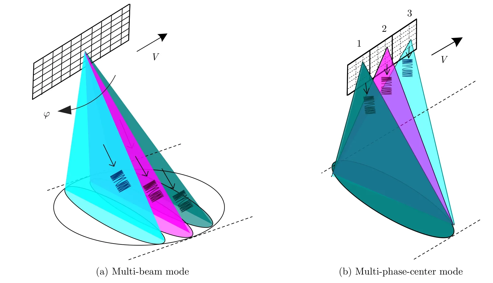
Fig.1 Azimuth MWE on transmit
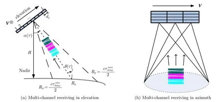
Fig.2 Azimuth MWE on receive

and the series of mutually time shifted waveforms are represented by
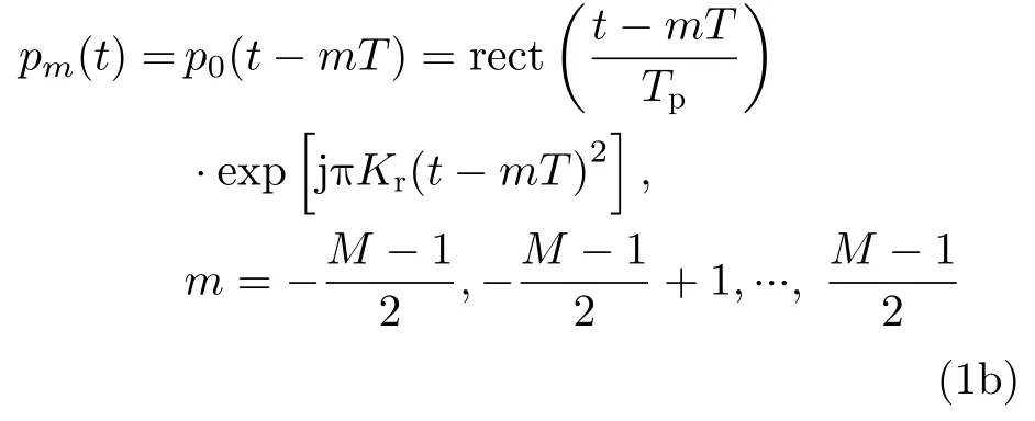
whereTis the unit linearly shifted time andT ≥Tp,which provides a sufficient mutual range delay that can be separated by DBF on receive in elevation.Note that here in order to give a unified form for both cases whenMis odd or even,here the subscript valuem,denoting the subpulse number,does not have to be an integer itself (mis increased by integers).
By merely switching between different antenna beams or subaperture elements during each transmitted subpulse,the generation of the timeshifted chirped subpulses is quite simple.As an alternative,the Short-Term Shift-Orthogonal(STSO) waveforms was proposed[11].The linear time shift in Eq.(1b) is replaced by cyclical time shift to ensure the simultaneous transmission via multiple orthogonal transmit channels.Owing to the cyclical time shift,the transmitted signals from any two different channels will fulfill the following short-term shift orthogonality[11]

2.3 Default assumption in this paper
For conciseness,in this paper,the analytical derivation and simulation are dedicated to the AMWE SAR mode with multiple azimuth subbeams on transmit.Owing to the similar transmit/receive antenna architecture in elevation dimension,the multi-waveforms separation manner here is also feasible for the multi-phase-center mode[4]if the same time-shifted chirped waveforms given in Eq.(1) is also used.If STSO waveform encoding scheme is used,due to the similar chirped-pulse-based signal structure,the method presented in this paper will also be feasible after some necessary modifications.
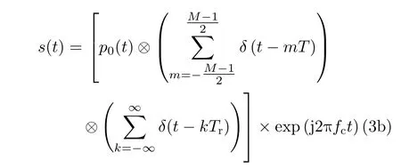
For an AMWE SAR system withMazimuth subbeams on transmit as shown in Fig.1,Mtransmit waveforms are transmitted in every pulse repetition interval (PRI,denoted asTr),each corresponding to a subbeam.The complex form of the overall transmit signal is represented by

wherefcis the carrier frequency,kis the PRI number,δ(t) represents Dirac function,and⊗denotes time domain convolution.When a set of mutually time-shifted chirped subpulses described by Eq.(1) are used,s(t) can be further represented by
As for the imaged scene in presence of topographic height variations,like the assumption used in Ref.[8],we consider an instantaneously illuminated swath characterized,along the isorange lines,by a homogeneous backscattering surface and constant topographic height.This means that in elevation the layover effect does not occur,and in azimuth,a mean height of all contributing backscattering within the illuminated azimuth extend is sufficiently representative.Though simple,this reference surface allows for a first stage comparison for achievable performance in the simulation of this paper.
3 Cascaded Digital Beamforming Networks in Elevation
3.1 Structure and signal model of cascaded DBF networks
The structure of cascaded DBF networks in elevation investigated in this paper is given by Fig.3.The total receive aperture in elevation is split intoL0subapertures.The size of each subaperture isd0.In the following of this paper,each subaperture with sized0is called an “antenna element”.Due to the relatively small scan angle needed for the onboard beamforming,the element spacingd0is not restricted by half wavelength[7].With a properly designed antenna height[4,8],a largerd0can reduce the element numberL0,which is pre-requisite considering the downloaded data volume for a system employing a posteriori DBF only on the ground[8]; However,this will also narrow the beam of each antenna element.In this paper,since an onboard DBF network is used and the downloaded data volume is no longer dependent onL0,d0should be small enough so that a near constant element-level gain within the swath can be held.
For each antenna element,the signal is received,demodulated and digitized separately.As shows in Fig.2 and Fig.3,suppose that the first element is selected as the reference channel in elevation,according to Eq.(3),the baseband echo of themth subpulsepm(t) in thekth PRI received by the reference elevation channel after coherent demodulation is given by

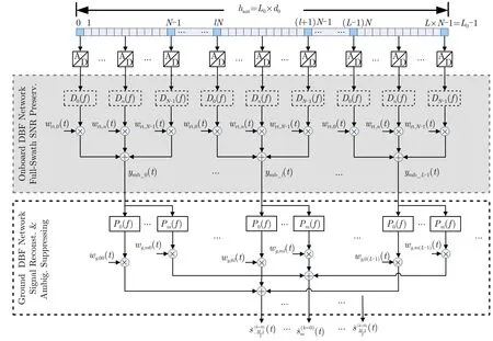
Fig.3 Cascaded DBF networks in elevation performing the SNR-preserving and interferences-free signal separation
Note that hereτalso represents the slantrange position on the ground,so that the off-nadir angle α and incidenceθin Fig.2 can be represented as single-valued functions of delay if ignoring layover effect,according to the basic assumption given in Section 2.3.To a first approximation,these functions can be determined from the orbit and the given Earth model[6],however,their true values cannot be simply modeled.Also note that in order to give a concise form,the transmit antenna pattern and the receive element-level pattern are included inA detailed description forunder the homogeneous white reflectivity assumption can be found in Ref.[8].For thel0th antenna element,the demodulated echo of the same subpulse can be expressed in a similar integral form as

In comparison with Eq.(4),there is an extra demodulated phase term introduced by the additional trip delaywhich is given by

whereα0is the off-nadir angle of the antenna normal boresight,βis the off-normal direction angle,c is the speed of light.Besides the above phase shift,there still exists a small envelope delay for the receive time.The enve-lope shiftcan be ignored[6–8]if the signal bandwidth is not wider than the array bandwidth[20],which is the usual case for most current spaceborne SAR using phased array method.In this paper,this conventional phaseshift DBF case with narrowband signal is assumed,therefore,in the following expressionst′tis adopted.In a very high-resolution case,however,such an approximation may cause frequency dispersion phenomenon in beamforming if the signal bandwidth is much wider than the array bandwidth[20].Then a time-varying time-delay network implemented by FIR filtering,or specially designed subband-based scalloped beamforming is essential to fulfill broadband DBF compensation.One can find a detailed description for this issue in Ref.[20].
As shown in Fig.3,theL0antenna elements are then partitioned intoLgroups,each group hasNelements and forms a larger subaperture with the sizeN ×d0.In the following,a subaperture refers in particular to such a group of antenna elements.In general the overlapping of subapertures is permissible,but it is not considered here for simplification.Letdenote the echo from themth transmit subpulse in thekth PRI received by thenth element (n=0,1,···,N −1) within thelth subaperture (l=0,1,···,L −1),according to Eq.(5),can be further expressed as

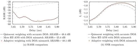
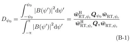
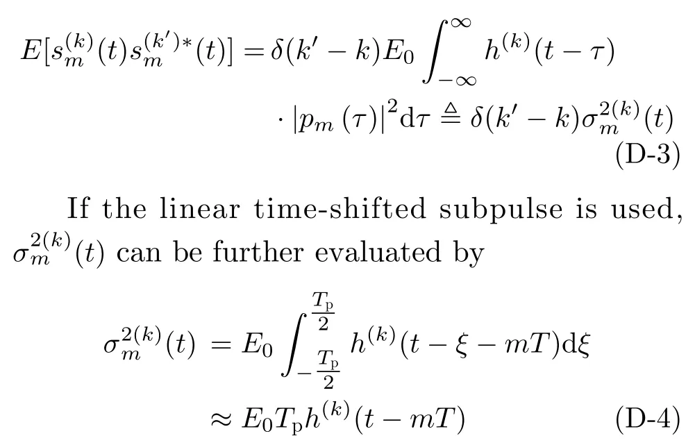
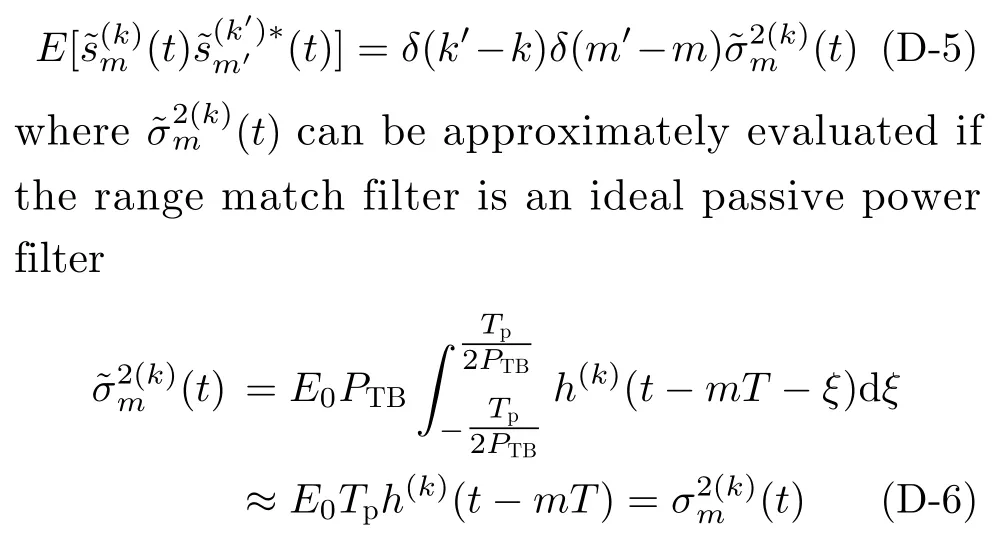
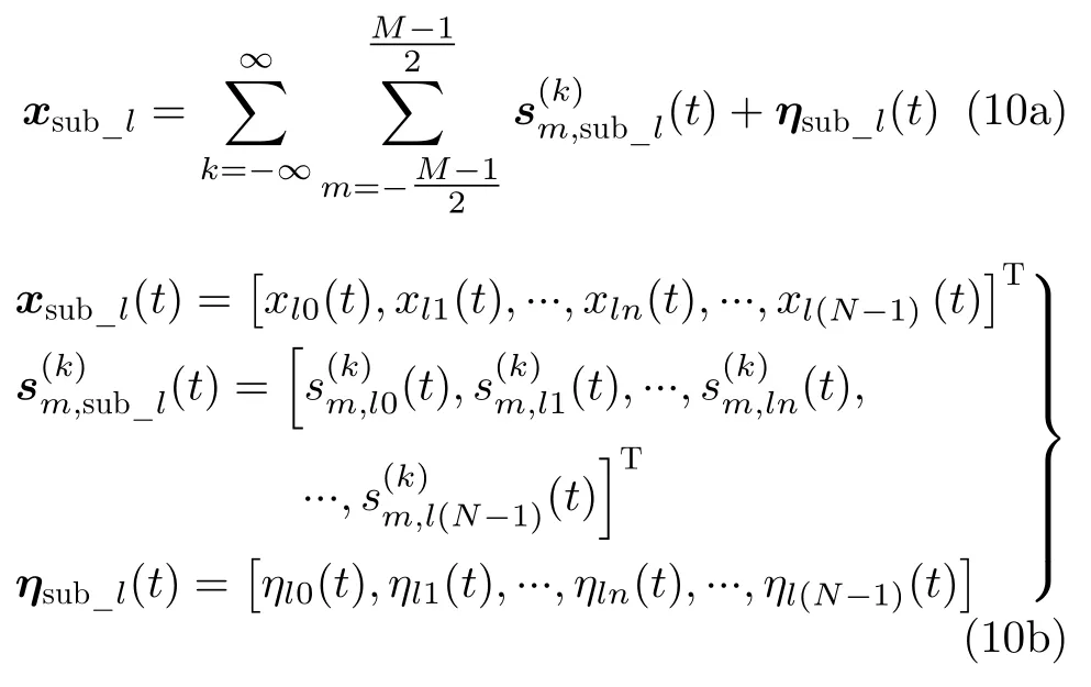
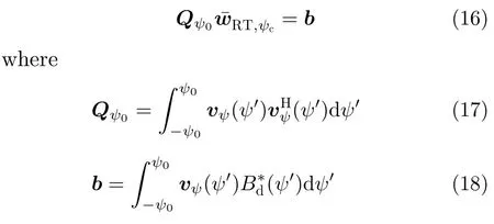
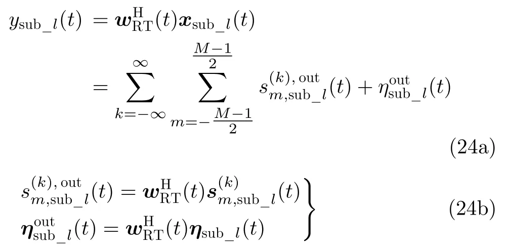
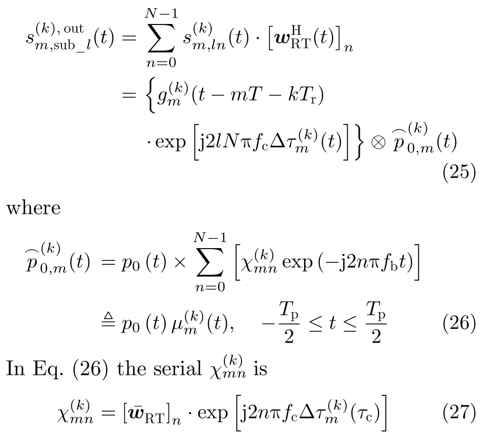
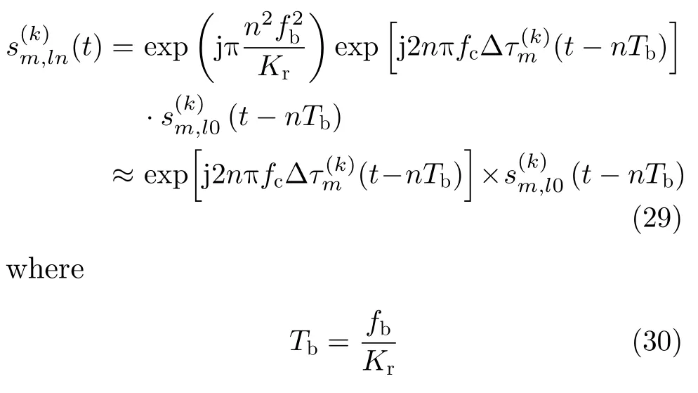
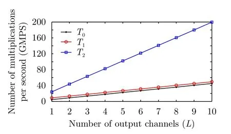
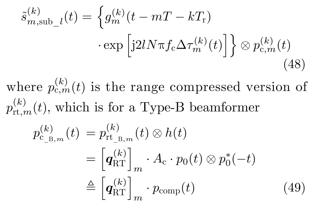
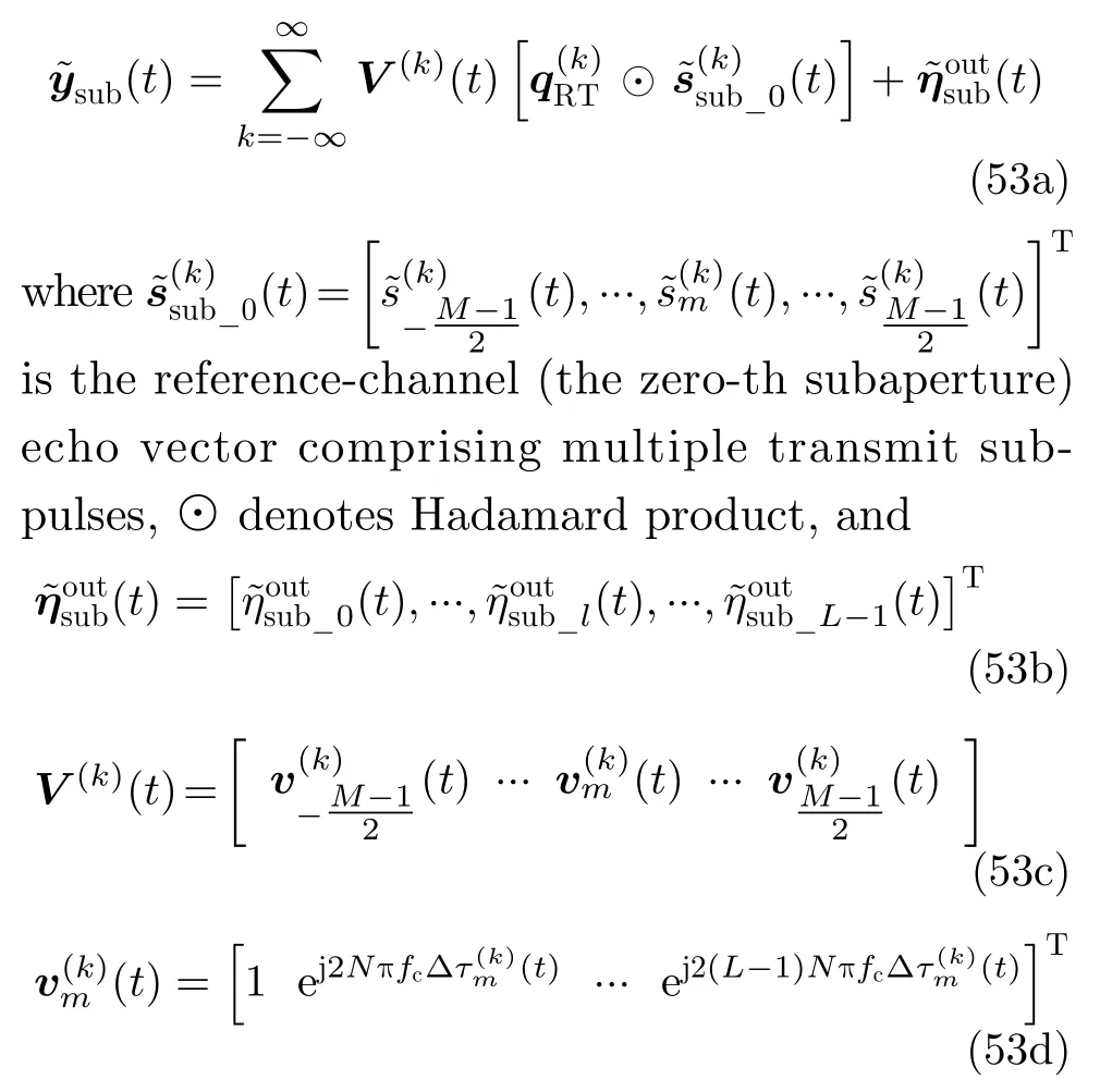
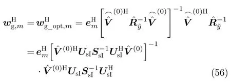
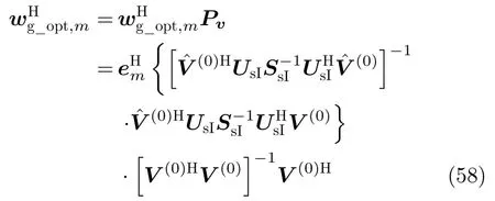
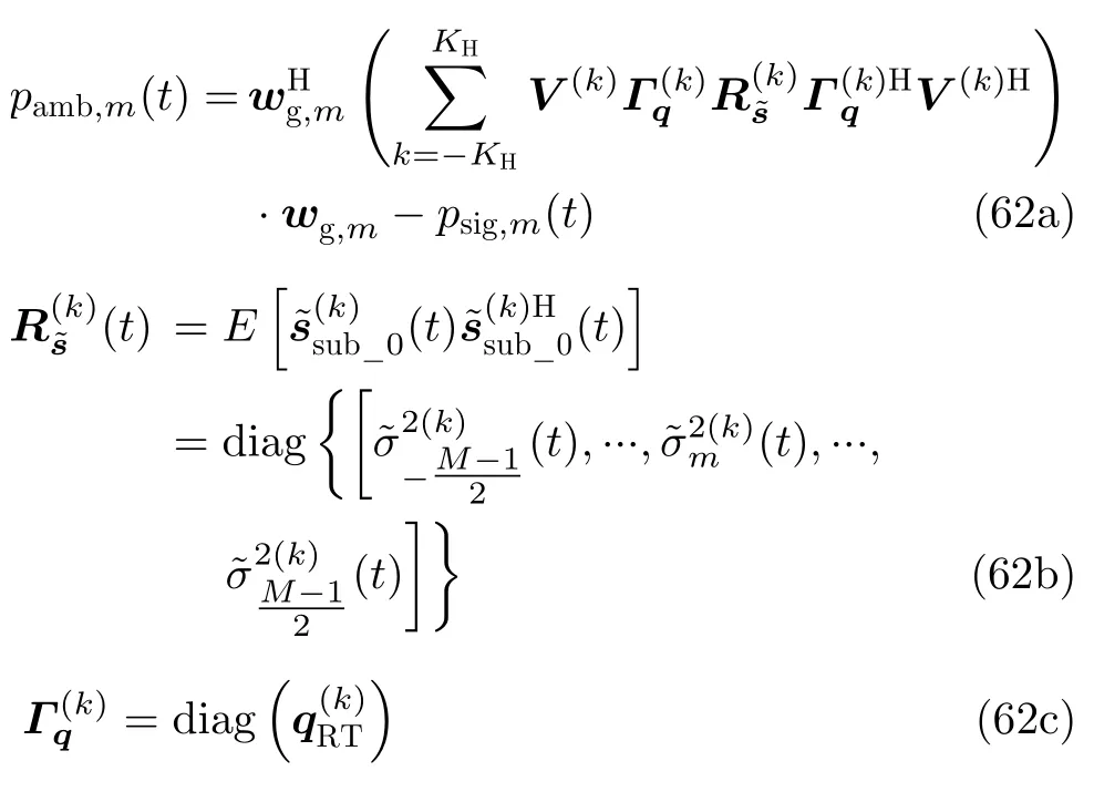
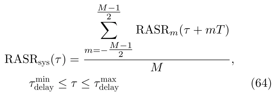
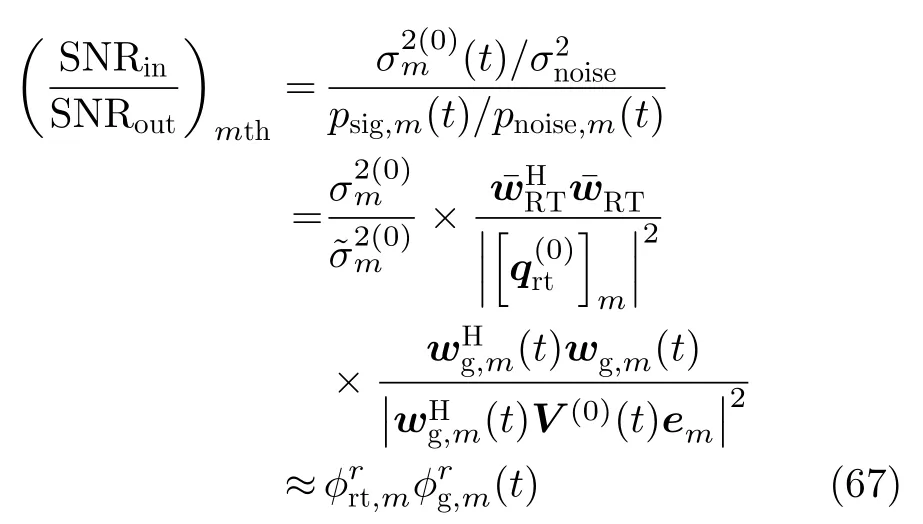
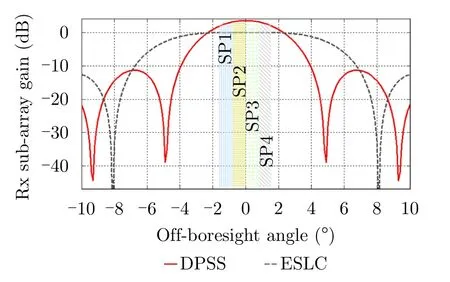
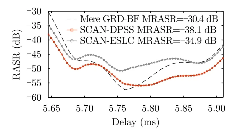
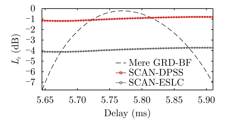
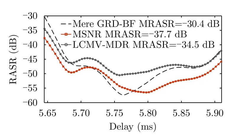
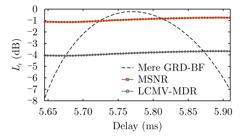
The time-variant exponential terms outside the integral in Eq.(7) for each receive elements are always connected to the center look angle of the given subpulse at a given time,which constitute the time-variant steering vector associated with that subpulse and further determine the time-variant weighting vector of the scanning beam in Refs.[6,7].However,the exponential term containing inside the integral isdependent on the intra-pulse time variableξ,which will make an unwanted intra-pulse element-dependent phase weighting in the pulse extend−Tp/2≤ξ The above compact linear signal model is used to develop DBF methods in Ref.[8] for reconstructing the unambiguous signalfromXcomp,sub_l(t).However,for the non-rangecompressed raw data in Eq.(7) onboard the satellite,if the phase valueis also directly omitted within the uncompressed pulse duration,the influence of PEL may deteriorate the system performance.Therefore,here thelth-subaperture input signal (including the additive noise) of the first-stage beamformer will firstly be written in its initial form given by the following Eq.(10),later we will re-derive a similar model like Eq.(9) for the range-uncompressed signal in Section 3.2.3. In Eq.(10)ηln(t) is the additive noise of thenth element in thelth subaperture.The main purpose of the first-stage onboard DBF within each subaperture is to optimize signal power of the multiple transmit waveforms/subpulses for improved SNR performance over the whole swath.At the same time,the output data volume can beN-times reduced onboard the satellite. By combining theNelements of the vectorxsub_lwithin each subaperture,the output of each subaperture is a scalar signal denoted asysub_l(t).The output signalsysub_l(t) (l=0,1,···,L −1) from different subapertures constitute the input vector of the second stage cascaded DBF network In this stage null-steering DBF is performed on the ground to realize the reliable extraction of echoes fromMtransmit subpulses,i.e.free of mutual interferences,by flexibly and adaptively placing nulls of the array pattern. Both the onboard realtime ANS beamformer in Ref.[7] and the ground a posteriori DBF in Ref.[8] can be viewed as special cases of the hybrid cascaded DBF networks in Fig.3.For the onboard ANS DBF network[7],the second-stage DBF in Fig.3 is omitted; in the onboard part,now the number of the onboard beamformers isL=M,and the number of the elements within each beamformer isNL0.It means that each“subaperture” here is extended to the full aperture and mutually overlaps completely.For the ground a posteriori DBF network[8],it can be considered that there areLL0subapertures in the onboard DBF network,and each subaperture beamformer only has one antenna element and acts as a direct through connection filter. In order to optimize the overall signal power and minimize signal distortion over the whole swath in each subaperture onboard the satellite,a properly designed digital subaperture beam,which is much wider than the full-aperture sharp beam in ANS-DBF[7],should be formed and follow the multiple radar subpulses as a whole when they travel on the ground,keeping enough high receive gain within the entire instantaneous scattering field at any instance of time.For onboard DBF,the off-normal direction angleβ(τ) has to be predetermined by a assumed model.Fortunately,here the formed subaperture beam is much wider and no deep null is needed,the accuracy demand forβ(τ) is not high. Given a pulse durationT,the ground range pulse extentχrg(T,β) and corresponding angular pulse extentχβ(T,β) can be calculated and their expressions have been given in Ref.[21].For a MWE SAR system,since the whole transmit duration isM ×T,the instantaneous angular pulse extent covering the entire instantaneous scattering field becomesχβ(M ·T,β(τ)).In Ref.[8] it has been analyzed that if the subaperture numberL>M,it will not be difficult for a system designer to have a nominal 3 dB-beamwidth of each subaperture larger thanχβ(M ·T,β(τ)),so that the PEL influence is comparatively limited. 3.2.1 Beamformer design for instantaneous scattering field This subsection aims at optimizing the DBF weightingfor the instantaneous scattering field at the center of the swath,i.e.tτc.Letβ0χβ[M ·T,βcβ(τc)]/2,representing the half angular pulse extent atτc.With a given weighting vectorthe array pattern function of an antenna subaperture can be written as It is evident that if Eq.(14) is satisfied,the spatial filtering within the instantaneous pulse extent is fixed-gain and no amplitude modulation and relevant losses will be introduced on each subpulse.In other words,it is an intra- and intersubpulse distortionless “optimum” spatial filter.The following square error is defined by Based on the “zero gradient” method the following constraint equation is derived: It is easy to derive thatQπ2πIN,INis aNdimensional identity matrix.It implies that if the subaperture pattern control is performed on the whole unambiguous region [−π,π],thenis a full rank matrix,no remaining DOFs are available to further optimize the signal-to-noise level.Fortunately,Here the constraint is given in a small angular region [−ψ0,ψ0],eigenvalues ofQψ0will drop down quickly.If only the principal components in eigen-space ofare used to the form the constraint Eq.(16),then more DOFs are available for subaperture-level SNR optimization.The principal-component version ofcan be written as wherekpis a turning parameter and its value is set as 1 here.By using the principal component method,the constraint Eq.(16) can be rank-reduced and converted to Under the above Eigen-Space Linear Constraint(ESLC) set,by exploiting the rest subaperture DOFs to keep minimum output noise power,one can derive the following weight vector as 3.2.2 Beam scanning and subaperture-level output In theory,it is possible to optimize the realtime weighting vectorat any instance of timet.Due to the normally small scan angle needed for the onboard beam for ming,χβ[M ·T,β(t)] only changes slightly witht.By utilizing the relationship expressed in Eq.(A-5)for the pulse-centred steering vectors,the realtime scanning subaperture-level beam can be practically designed with two steps:first,a “static” beamformer (corresponding toin the previous subsection) is optimized aimed at the instantaneous scattering field [−β0,β0] (may leaving some margin forβ0) at the swath center,then a real-time scanning is added to chase the whole pulses.Accordingly,the time-variant weighting vector,after the real-time scanning is added,can be represented by where theN ×Ndynamic steering diagonal matrixΛH(t) is defined by Eq.(A-6). According to the input signal model given by Eq.(10),the output signal of thelth subaperture is then given by According to the expression ofandcan be further written as 3.2.3 Alternative approach exploring subpulse structure information If the prior information of the chirped subpulse time-frequency structure is utilized,the received echogiven by Eq.(7) can be further rewritten as In Eq.(28) we use the linear relationship between the off-boresight angle and echo delay[6–8,22]implied in Eq.(A-7),so that can be ap-proximated as a linear phase term corresponding to a frequency shift (lN+n)fb.By exploiting the relationship of a LFM signal between time-domain and frequency-domain shift,within each subaperture,one can approximate thenth-element signalwith the time-shift version of its subaperture-level reference signalas is the equivalent time shift coupled with the freque ncy shiftfb.For brevity,the phase term expis neglected since it is small and can be easily compensated.From Eq.(29) it is found that owing to the same linear connection between time and frequency within each chirped subpulse,the additional intra-pulse phase shift−2nπfbξ(relative to the reference channel) varying linearly over the subpulse extent can be equivalent to a relative time delaynTb.It should be noted that now the FIR interpolation filtering(see the optional filtersDn(f) in Fig.3) is essential,and the first step of the onboard network is to implement the following linear frequency-dependent phase shifts within each group of antenna elements which introduce different time delays in the signal paths of the individual antenna elements within each subaperture prior to the following beamforming,to make the beamforming frequency-dispersive and mitigate the effect of the pulse extension.After this step,the input signal vectorxsub_lin Eq.(10) now becomes and according to Eq.(30) can be further written in matrix form as In comparison with the range-compressed signal model given by Eq.(9),it is found that after the linear frequency-dependent phase compensation performed byDn(f),Eq.(33) gives a compact linear model for onboard real-time beamforming which has exactly the same form for the ground a posteriori DBF in Ref.[8].This means the already well-developed DBF algorithms can be directly used here after some necessary modifications. For instance,with a reasonable optimization criteria to keep the signal distortionless while simultaneously minimizing the response due to noise,using the Linear Constrained Minimum Variance (LCMV) method[7,8],one can derive the following real-time weight vector as wheregDRis the distortionless response constraint vector,andRη(t) denotes the noise covariance matrix.Note that directional range ambiguities from other PRIs (k0) are ignored to simplify the real-time beamforming,and the noise is assumed to be white and complex normal distributed with zero mean and noise powerThencan be shortened as its quiescent state form It is easy to find that the weighting vector in Eq.(34) and Eq.(35) have almost same forms with the ones which are given in Refs.[7,8] derived with the same LCMV method.Nevertheless,it should be noted that there is still a major difference on the definition of the constraint vectorgDR.In this paper,gDRcomprisesMdistortionless response constraints for each subpulse and should be denoted asgMDR It is reasonable since here it is not the duty of the onboard DBF to do the echo separation,so that no null is needed.However,in Refs.[7,8],it is defined as themth column vector of theM×Midentity matrix.In this case,M–1 nulls are formed to cancelM–1 echoes from the corresponding subpulses,only one subpulse echo is distortionless retained. According to the relationship given by Eq.(A-5),can be further given by Just like what done in Section 3.2.1 and Appendix B,we can also derive a weighting vector to relax the distortionless demand but prefer SNR performance.In Appendix C such a SNR-preferis derived which can be an alternative ofin Eq.(37). One should note that the real-time weighting vectors Eq.(37) are normally configured in a deterministic manner onboard the satellite,so thatA(0)andΛH(t) in Eq.(37) are predetermined based on an assumed earth model.The output signalsysub_l(t) from each subaperture are then given by which will ensure the distortionless responses,and for the maximized SNR weightingnow is Since the elements in aboveis normally unequal,a certain inter-subpulse relative distortion will occur as the price of maximizing SNR. 3.2.4 Analysis of realtime computational load For the purpose of analyzing the realtime computational load of the proposed onboard DBF,the amount of real multiplications is derived in this subsection.It is known that the proposed realtime DBF approach in Section 3.2 is a deterministic DBF process.The fast-time-variant weighting vector in Eq.(23) is pre-determined and those weighting coefficients can be calculated in advance and stored in the onboard memory.However,since for each fast-time sample,aN-dimensional complex weighting vector is to be stored,a total huge onboard memory size is needed for the whole receive window.In order to save onboard memory,as a reasonable compromise,we can only calculate in advanceandΛ(t) in the time-variant weighting vector of Eq.(23),then for each fast-time sampling time,an additional computational load ofN-point complex multiplications is essential. AssumingYfast-time samples in the receive echo window,the whole number of real multiplications of the present DBF processing for the Type-A beamforming given in Section 3.2.1 can be expressed as In Eq.(41),the first term after the equal sign represents the added real-time computation forNcomplex weighting coefficients calculation,where 3 real multiplications for realizing one complex multiplication is assumed[24]. In order to realize the Type-B beamforming scheme discussed in Section 3.2.3,it should be noted that besides the above additional computational load,now a FIR interpolation filtering for each antenna element channel is essential.Considering aP-order FIR interpolation filter is used in each antenna element channel,according to the ROP (Resource Occupation Reduced) processing scheme given in Ref.[24],now the whole number of real multiplications of the Type-B DBF processing can be expressed as As a reference level of onboard computational load,assuming with the same digital receiving structure of the DBF SAR and only employing the basic power combination among the multiple onboard channels toward a fixed direction in a digital way like the method given in Ref.[8],the number of real multiplications can be expressed as The comparison betweenT1,T2andT0is illustrated in Fig.4.The parameter values in the simulating is in accordance with the simulation given in Section 5.It can be seen that although the Type-A beamforming scheme implements an onboard time-variant beam scanning for SNRPreserving,under the same output channel number,the additional realtime computational load is small in comparison with the present computational load level only implementing basic digital power combination toward fixed direction[8].For the Type-B beamforming scheme,however,the added realtime computational load is sizable and should be considered in practical use. 3.3.1 Range focusing and the unified range-compressed signal form Before signal reconstruction processing in elevation on the ground,data should be range focused first to minimize the pulse extension.Under the condition that the time-shifted chirped subpulse waveform scheme given in Eq.(3) is em- Fig.4 Number of real multiplications per second of the proposed two types of onboard DBF processing and the reference beamforming processing given in Ref.[8] (N=5 and P= 8) ployed,a common match filter can be used for multiple transmit subpulses whereAis a constant amplitude which keeps matched signal output energy unaltered.From Eq.(25) and Eq.(38),it is easily known that whether the Type-A beamformers derived in section 3.2.1,or the Type-B beamformers further exploring subpulse structure information in section 3.2.3 are used,the output signal corresponding to the echo of themth subpulse in thekth PRI can be expressed by the following unified form for thelth subaperture and for the Type-B case,according to Eq.(38),is denoted asand expressed by Note that for a Type-A beamformer,there exists possible intra-subpulse distortion functioncaused by the time-variant array pattern weighting,which may cause a degree of mismatching for the matched filtering Eq.(44).The matched filtering output ofdenoted asthen can be uniformly represented by and for a Type-A beamformer In above two equations,pcomp(t) is a sinc-type function.Note that in Eq.(50) an approximation is made that the defocusing effect of mismatching caused byis ignored and the peak gain decreaseis concerned,which can be expressed as By comparing the Type-A version in Eq.(50)and the Type-B version in Eq.(49),it is clear that if we redefine the vectorwhosemth element is equal tothen we can unify the two type of beamforming signal models after range focusing,only keeping in mind that the real meaning ofis not the same.Using the same shortpulse-extent approximation which has been explained for Eq.(A-1),one can easily derive the following relation then the full form of the output signals from theLchannels of onboard Type-A or Type-B DBF network,ie.can be represented in matrix form as 3.3.2 Ground reconstruction DBF algorithm The linear signal model given by Eq.(53) will pose the following basic constraints on the ground weighting vectors to reconstruct the SAR returns from multiple transmit subpulses A widely used robust DBF technique which offers better protection for desired signal gain under DOA mismatch is diagonal loading,which will work well if interferences are much stronger than the desired signal[26].However,it is obvious from Eq.(54) that 'interference' and 'signal' are interchangeable.Echoes from different transmit subpulses are with similar power level,at this point diagonal loading is not quite a suitable solution.Other methods to enhance the DBF robustness against the DOA mismatch include imposing additional derivative constraints[26],covariance matrix tapering technique[27]and so on.These methods can offer wider response at the look angle corresponding to the desired transmit subpulse,or even widened nulls for interferences from other transmit subpulses.However,one has to devote much more additional system DOFs,it means here that the onboard output channel numberLshould be much larger than the subpulse numberM.This condition obviously goes against the original intention to minimize onboard output channels. In summary,the ground reconstruction based on the signal model Eq.(53) has the characteristics as follows:(1) the signal-plus-interference numberMis known in advance (returns from other PRIs or layover sources are omitted); (2) a comparatively high and stable signal/interference power level relative to noise is predictable,considering the demanding SAR application requirement; (3) only a limited system DOFs are offered,due to the data downlink rate limit. According to above characteristics,a two-step strategy is considered here.First,a DOA-estimation preprocessing step is introduced for the known number of transmit subpulses based on the range compressed array data,which can significantly reduce the source DOA uncertainty,owing to the high and stable signal/interference power level relative to noise.Then,Eigen-Space based method is employed to improve robustness:each steering vector (column vectors ofV(0)),after renewed with the estimated DOA,is projected to the estimated signal-plus-interference subspace obtained via the eigen-decomposition of the sample covariance matrix,in order to further reduce steering vector errors caused by the residual DOA errors. Supposing that using a direction-finding algorithm like Root-MUSIC[26],look angels ofMreturns are estimated andis calculated according to Eq.(53c),in the meantimeis obtained by the eigenvalue decomposition ofwhich is the estimated covariance matrix ofwhere ΣsIis the diagonal matrix comprisingMprincipal eigenvalues ofUsIis the signal-plus-interference subspace matrix comprisingMprincipal eigenvectors.Then the modified constraint matrix after the signal-plus-interference subspace orthogonal projection is Then the optimum beamformer maintaining distortionless response to the desired signal while minimizing the output interference-plus-noise power can be represented by It is clearly thatwg_opt,mis within the signalplus-interference subspace spanned byUsI,which is the same subspace spanned byV(0).If defining the following orthogonal projection matrix the orthogonal projected version ofwg_opt,mon the signal-plus-interference subspace is given by Under the condition that the estimation ofV(0)is enough accurate,ignoring the difference betweenandV(0)in the brace of Eq.(58)yields It is obvious that the derivedis in form the optimal quiescent weight vector of the well-known LCMV (linear constraints minimum variance) beamformer subject to the constraints of Eq.(54).It is also the analytical least square solution[8,26]subject to Eq.(54). Since a unified range-compressed signal model and ground signal reconstruction DBF algorithm can be established in Section 3.3,an uniform performance analysis can be given.According to Eq.(53),echo from themth transmit subpulse is separated unambiguously bywg,mand can be written as whereKHdenotes the maximum range ambiguity number in consideration.The first term in Eq.(60)represents the unambiguously reconstructed returned signal from themth transmit subpulse,the corresponding signal powerpsig,m(t) is The second and the third term in Eq.(60) represent respectively the ambiguous components inside or outside the PRI,corresponding to residual interferences from other subpulses transmitted in the same PRI due to nonideal suppression,or ordinary sidelobe range ambiguity weighted by DBF network.According to the results in Appendix D,the total power of these ambiguous components is given by The RASR corresponding to themth transmit subpulse (also themth azimuth subbeam for the multi-beam mode) is therefore evaluated by Under the approximation that each transmit subpulse contributes the almost same signal power[8],the systemic RSAR for delaycan be further evaluated by The last term in Eq.(60) represents the ultimate output noise from the cascaded DBF networks,which is the weighted sum ofLnoise componentsUnder the approximation that the noise bandwidth is equal to the signal bandwidth,taking account thath(t) is an ideal Passive Power Filter (PPF),it is easily derived that the noise power ofis given by The local SNR scaling by the cascaded DBF Networks in elevation corresponding to themth subpulse is therefore evaluated by It is easily understood from its definition thathas an optimum minimum value 1/L0,which means that the DBF network has oriented its maximum array gain toward the desired signal[8].Also,it should be noted thatis a scaling factor of the output SNR relative to the input element-level SNR due to the DBF-network,therefore the effect of the element-level antenna gain changing in response to the element sized0to the ultimate output SNR is not counted.Supposing that the total receive antenna heightHanthas been predetermined to meet the requirement[4,8]for a reliable separation of multiple subpulses,then with the known conditionHantd0×L0,the output system SNR for a DBF network different antenna element size,i.e.,d0andis given by In Ref.[8],it has been demonstrated by simulations that under the DOA mismatch condition,the underground a posteriori process employing adaptive beamforming is promising to provide much better performance compared with the realtime deterministic DBF[7],however,a more than double onboard channels and data downlink rate are required as the cost. This paper,as a continuation,will mainly illustrate the achievable performance improvement of the cascaded hybrid DBF networks by making a direct comparison with the a posteriori DBF in Ref.[8] under the same MWE SAR mode employing multiple azimuth subbeams on transmit.Therefore,we consider a design example of an Xband spaceborne SAR with an azimuth resolution of 1.5 m and a swath width of 100 km,which has the same essential parameters (summarized in Tab.1) as the exemplary system simulated in Ref.[8].A transmit signal withM=4 chirped subpulses is assumed,each subpulse has a bandwidth of 250 MHz and a duration of 40 µs,and is mutually time shifted[4],the interval time between adjacent subpulses is also 40 µs.The transmit signal scheme is same with that given in Ref.[8].The antenna height is properly designed and equal to 2.33 m,which meets the subpulse-separation requirement on the antenna height given by the Eq.(28) in Ref.[8].The timing diagram of the exemplary system can be found in Fig.2 of Ref.[8]. The only difference is the onboard output data channel numberL,which is equal to the number of the subapertures in elevation.In Ref.[8]LL0,and its value is variable and tested from 5,6,10 up to 150.It is pointed out in Ref.[8] that since no onboard realtime DBF network is employed,the channel numberLis restricted by four inherent constraints,these constraints include the reliable signal separation constrain,the swath-bor-der gain-drop constrain,pulse-interval efficient utilization constrain,and the DOF constrain[8].In order to satisfy the multiple constrains,a channel numberL=10,which is 2.5 times of the transmit subpulse number (i.e.M=4),is required,especially for avoiding significant signal gain loss at swath borders.In this paper,however,owing to the employment of the onboard real-time scanning DBF network,the original swath-border gain-drop restrict is relaxed.A channel numberL=6,which is only slightly larger than the transmit subpulse number,is selected and demonstrated in the following simulation. Tab.1 Parameters used in the system simulation[8] In azimuth dimension,under the selected PRF=1310 and the processed Doppler bandwidth of 4890 Hz,with four azimuth subapertures,the azimuth ASR after intra-subbeam azimuth spectrum reconstruction and inter-subbeam spectrum combination is approximate –30 dB,according to the azimuth-dimensional reconstruction algorithms given in Refs.[3,6].The following simulations will be focused on the performance in elevation dimension only. In the following simulations,the true topographic heights of the imaged scene are deliberately set with a deviation of ∆h250 m relative to the given default earth model.Though it was found in Ref.[23] that the main-beam gain and SNR loss caused by such a height deviation is neglectable for the SCORE deterministic beamforming in a DBF-SAR system,the RASR degradation for the deterministic ANS DBF in a MWE-SAR system is already unacceptable[8]. At the first stage of the simulation,for the purpose of providing explicit and quick assessing the achievable best performance for the presented hybrid DBF networks in comparison with the a posteriori DBF in Ref.[8],a standard array is assumed,and also assumed is that in both cases the DOA mismatch can be accurately handled by the ground DOA-estimation and robust beamforming in the ground.By settingd0λ/2,there areL0150 antenna elements in elevation constituting the full aperture with the height of 2.33 m.For the ground part DBF network,since the data-dependent adaptive beamformer given by Eq.(56) will very close to its quiescent form if accurate DOA information is available,we will directly employ the optimal quiescent LCMV weighting vector given by Eq.(59) with true DOA to avoid the uncertainty caused by data-dependent algorithm.For the a posteriori DBF, LL06 is directly set,and the same quiescent LCMV weighting vector is also used for the sake of fairness.On the satellite,for the onboard DBF network,weighting vectors are calculated with the deterministic DOA information according to the default earth model. The cascaded hybrid DBF networks employing onboard Type-A beamforming presented in Section 3.2.1 are investigated first.The array patterns of the distortionless-preferred ESLC beamformer and the SNR-preferred DPSS beamformer are shown in Fig.5 fortτc.The two weighting vectors are power normalized to the power level ofto keep the same output noise power level.Over the extent of each transmit subpulse,there is a corresponding variant array gain weighting function.Therefore,as shown in Fig.5,each subpulse extend is mapped into a given segment on the abscissa axis,which is indicated by a vertical bar.The amplitude variation in the extent of each subpulse will cause the intra-subpulse distortion and can be represented by the functionaccording to Eq.(26).In Fig.6,the different distortion functionsfor mul- Fig.5 The array patterns of onboard Type-A beamforming at instantaneous time t=τc tiple subpulses are simulated and shown for the distortionless-preferred ESLC and the SNR-preferred DPSS beamformer,with gray line and red line respectively. It is shown in Fig.5 that indeed the distortionless-preferred ESLC beamformer can output a nearly constant gain for each subpulse.From the enlarged view in Fig.6(b),the distortion functionsfor the four subpulses are flat enough with only a ±1.2 dB of gain variation.However,it is obvious that the distortionless response is achieved at the price of considerable array gain loss.The SNR-preferred DPSS beamformer,on the contrary,can get higher signal gains with mild inter- and intra-subpulse distortion.With the given system parameters in the present example,by maximizing the antenna directivity on the entire instantaneous scattering angular region,the DPSS beamforming gets an array pattern which has a main-beam shape similar to that of the normal beamformer,but with a lower side-lob level implying a more powerful ambiguity-suppression ability.The 3 dB-mainbeam width is slightly wider than the angular region covering the entire instantaneous scattering field containing 4 subpulses.From Fig.6(a),it is shown the distortion functionsfor the four subpulsesare within an acceptable ±1.2 dB of gain variation.The form ofis known and can be compensated in the processing. In Fig.7,performance comparison on RASR between the hybrid Type-A DBF networks and the a posteriori DBF[8]is provided,with the same onboard data channel number (L6) and same antenna height.It is found that with the DPSS hybrid DBF networks,either the swath average value (–49.3 dB) or the worst case value (–38.1 dB) of RASR is much better than that of the ground DBF (–47.1 dB for average and –30.4 dB the worst),due to its time-variant weighting fulfilling optimization of the overall signal power over the whole swath.With the ESLC hybrid DBF networks,considering its signal gain loss for the sake of keeping distortionless response,the RASR values in average (–35.4 dB),though quite acceptable,are not as good as the ground DBF,however,at swath borders,the worst case value(–34.9 dB) is still much better.Normally the worst case maximum RASR is a key indicator for performance evaluation. The corresponding SNR performance comparison,i.e.the normalized total SNR lossLr(τ) further counting the effect of the element-level antenna gain variation,is given in Fig.8.It is shown that the performance of the cascaded hybrid DBF structures on the total SNR lossLr(τ)relative to the achievable optimum SNR is much better and evenly distributed in the whole swath than that of the ground DBF,especially at the swath borders,there is 6.6 dB SNR improvement for DPSS hybrid networks and about 3.6 dB improvement for that of ESLC.From this point,the SNR-preferred DPSS is recommendable.At the swath center,the value ofLr(τ) is slightly betterfor the ground DBF,it is reasonable,since for a staring illumination of each subaperture oriented to the swath center,a target at the swath center will get a invariable peak receive gain for each transmit subpulse in each subaperture. Fig.6 Amplitude of the distortion functionsin the extent of each of 4 subpulses From the Fig.3 in Ref.[8],it is found that with as many as 10 channels using the ground DBF,the swath-average RASR value is about–51 dB and the worst-case value is about –40 dB,at the meantime,the SNR drop is about 2.5 dB at swath border in Fig.4 of Ref.[8].Compared with the results in Fig.7 and Fig.8,it is easily found that by employing the onboard time-variant beamforming,with 6 onboard output channels,the cascaded hybrid DBF networks can achieve satisfactory performance on range ambiguity suppression which approximates that of the ground DBF with as many as 10 channels,and even have more excellent performance on SNR preserving at swath borders. Next,the Type-B hybrid DBF networks in Section 3.2.3 further exploring subpulse time-frequency structure information are investigated in a similar way.The array spatial patterns of the onboard LCMV-MDR beamformer and MSNR beamformer at timetτcon carrier frequency are shown in Fig.9.It should be noted that due to the linear frequency-dependent phase shifts in-troduced to signal paths within each subaperture prior to the followed weighted summation,echoes of the multiple transmit subpulses are given theoretically individual frequency-invariant gains,notwithstanding the uncompressed pulse extension and the time-variant array weighting.Therefore as shown in Fig.9,each subpulse can be mapped into a given point on the abscissa axis,which is indicated by a vertical dashed line,not a vertical bar in Fig.5 as a contrast.However,though in theory each subpulse can get a constant gain without PEL,it is not true that all subpulses can get the maximum peak gain of the array pattern just like the single-chirped-pulse case employing SCORE technique[15],due to the more complex inter-pulse chirped-subpulse structure. Fig.7 Performance comparison on RASR between the cascaded hybrid Type-A DBF networks and ground DBF in Ref.[8] Fig.8 Performance comparison on SNR between the cascaded hybrid Type-A DBF networks and ground DBF in Ref.[8] In Fig.10 and Fig.11,performance comparisons on RASR and SNR between the hybrid Type-B DBF networks and the a posteriori DBF[8]are given,respectively.It is interesting to find much likeness between the results of Type-B DBF (Fig.10,Fig.11) and Type-A DBF (Fig.7,Fig.8).So it is essential to give an across comparison between the onboard signal-structure-dependent beamformers (Type-B) and the non-signal-dependent ones (Type-A).For both types,according to thegiven optimization objectives,there are two categories of beamformers:SNR-preserving-preferred category (DPSS in Type-A,MSNR in Type-B)and distortionless-response-preferred category(ESLC in Type-A,LCMV-MDR in Type-B).Comparison results of these two categories are given in Fig.12.From Fig 12(a),it is found that with regard to the performance on RASR,there is no significant difference found if the transmit signal-structure information is used or not,either for SNR-preserving-preferred or distortionless-response-preferred category.With regard to the performance on SNR,however,there is a quite small advantage if the transmit signal-structure information is used,either for SNR-preserving-preferred or distortionless-response-preferred category.There are two aspects to explain why there is no remarkable advantage when prior information of the chirped subpulse time-frequency structure is utilized.The first aspect is that four-subpulses structure is complex enough,which prohibits all subpulses sharing the maximum peak gain of the array pattern like the SCORE case[22]; The second aspect is that the total and subaperture height is properly designed according to the multiple inherent constraints given in Ref.[8]. Fig.9 The array patterns of onboard Type-B beamforming at instantaneous time t=τc Fig.10 Performance comparison on RASR between the cascaded hybrid Type-B DBF networks and ground DBF in Ref.[8] Fig.11 Performance comparison on SNR between the cascaded hybrid Type-B DBF networks and ground DBF in Ref.[8] Fig.12 Across comparison of performance on RASR and SNR between the onboard transmit signal-structure-dependent beamformers(Type-B) and the non-signal-dependent ones (Type-A) At the second simulation stage,more practical considerations are included.First,the practical case when the antenna element spacing is larger than half of the wavelength is considered.The number of antenna element in elevation is reduced to 30,accordingly the antenna element spacing is increased tod02.5λ.With the new element spacing,the performance on RASR and SNR for the Type-A DPSS and Type-B MSNR beamformers are shown in Fig.13,both of which are SNR preferred.It’s found that the RASR values near the swath center deteriorate in some degree with the much larger element size,however,the deterioration of the average RASR in the whole swath or the worst RASR in the swath border is not significant.With regard to the performance on SNR,since the total SNR lossLr(τ) has accounted for the array element pattern,with a larger element size,there are inevitable deterioration at swath borders.In the given situation,the maximum deterioration is about 0.2 dB,which is acceptable under many circumstances. Next,besides the more practical elements size,the DOA mismatch condition in the presence of non-negligible topographic height error is further investigated.This time,a performance comparison between the cascaded hybrid DBF networks and the onboard real-time null-steering DBF[7]is given under the above condition.The echoes received byL030 elevation antenna elements,with additive thermal noise (Array SNR=5 dB,cf.Refs.[23,26]) are simulated in accordance with the signal model given by Eq.(10),with the homogeneous white reflectivity assumption.On the satellite,for the hybrid DBF networks the SNR-preferred Type-A scanning beamformer,i.e.wDPSS(t) is employed as representative,with the deterministic DOA information calculated according to the default earth model(with a deviation of ∆h250 m); For the onboard real-time null-steering DBF[7],the same deterministic mismatched DOA information is used.On the ground,for the hybrid DBF networks,the data-dependent adaptive beamformer presented in Section 3.3.2 is employed.In order to provide the reference theoretic optimum performance,a cascaded DBF networks employing ground quiescent beamforming using true topographic height information are also investigated. The final performance of the data-dependent cascaded DBF networks at 32 evenly distributed positions across the swath are simulated and evaluated,the corresponding results are shown in Fig.14 with diamond markers,in comparison with its theoretic performance curves,also with the performance curves calculated for the onboard ANS DBF[7].It is found that under the DOA mismatch condition in the presence of topographic height error,the performance of onboard ANS DBF employing deterministic real-time beamformer degrade,especially in the aspect of rangeambiguity suppression,an average RASR degradation as large as 23 dB is found.Nevertheless,by employing the hybrid DBF adding data-dependent a posteriori beamforming on the ground,although there are positions where observable degradations on RASR and SNR loss occur in contrast to the theoretic optimum performance under accurate DOA information,the full-swath performance as a whole does not deviate much. Fig.13 Performance on RASR and SNR for Type-A and Type-B SNR-preferred beamformers with an increased element spacing An important issue in a MWE-SAR system is the fulfillment of DBF on receive in elevation for a reliable separation of the mutually temporal overlapped echoes from multiple different transmit subpulses.In this paper,the performance of a separation approach employing hybrid DBF in elevation by combining the onboard real-time beamsteering and a posteriori DBF on the ground is elaborately investigated.From theoretical analysis and simulation,it is found that in comparison with the onboard real-time deterministic DBF[6,7],the employment of the hybrid DBF networks can avoid the “topographic height variation” problem under model mismatch conditionsin the presence of topographic height variations,at the price of a small increase of the output data volume (in the present example,corresponding to the increase of the output channel number from 4 to 6).In comparison with the a posteriori DBF on the ground[8],employing the hybrid DBF networks can get similar (or even better) satisfactory performance while remarkably reducing the output data volume (in the present example,corresponding to the decrease of the output channel number from 10 to 6).It then can be concluded that the hybrid DBF approach can provide additional dimension of the trade-space to optimize the performance on SNR & RASR,as well as reduce onboard data volume. Fig.14 Performance on RASR and SNR of the cascaded DBF networks under the DOA mismatch condition in the presence of topographic height error,in comparison with the onboard real-time null-steering DBF in Ref.[7] It is also found that by making use of the transmit signal-structure information (Type-B networks),there indeed exists extra advantage with regard to the performance on SNR preserving,although this advantage may be rather limited in practical situations.It should be noted that due to the time-variant onboard beamforming,in either case of the Type-A or Type-B onboard DBF Networks,the signal distortion in range dimension exists.Although the distortion can be sufficiently avoidable by introducing additional constrains,a price of considerable signal gain loss has to be paid,for either the Type-A or Type-B Networks.Theoretically,the intra-subpulse distortion caused by the real-time PEL effect for Type-B DBF Networks is mitigated by introducing time delay and forming desired frequency dispersion.However,extra embedded realtime FIR filtering for each input data channel is essential,which will increase the onboard digital resources requirement. Appendix A After range compression on the ground,as derived in Ref.[8],p0(ξ) in Eq.(7) is replaced by the compressed version:is the time-bandwidth product of the chirped subpulse),the pulse extent is compressed to only one range resolution bin 1/(KrTp),so the approximationis valid and the following equation can be derived A(k)(t) can be further expressed as where It should be noted that in the expression following the squiggly equals sign in Eq.(A-6),we use the linear relationship between the offboresight angle and echo delay at the swath center[6–8,22]implied in Eq.(A-7).It is pointed out in Ref.[5] that this approximation is effective for azimuth MWE SAR investigated in this paper,which is normally with a single swath.However,for elevation MWE SAR with multiple sub swaths discussed in ref.[5],this approximation may be invalid.In order to solve the multiple subswath problem,in Ref.[5] a spectrum-segment-based DSBF (digital scalloped beamforming) and adaptive multiple null-steering method is proposed.In this paper,for azimuth MWE SAR,we introduce two types of onboard digital beamformers (Type-A and Type-B) in the Section 3.2,and it will be found that Type-B beamformer will use the approximation in Eq.(A-7). Appendix B The generalized subaperture directivity defined on an angular extent rather than an angular point can be written as It is found that maximizing the generalized subaperture directivity is equivalent to maximizing the proportion of the power pattern in the region [−ψ0,ψ0] and the whole unambiguous region [−π,π].Eq.(B-1) has a form of the generalized Rayleigh quotient.According to Rayleigh-Ritz theorem[28],the optimumthat maximizes Eq.(B-1) is the eigenvector of the matrixcorresponding to the maximum eigenvalue: Appendix C Like what done in Appendix B,we can derive a weighting vector to relax the distortionless demand but prefer SNR performance.The optimization criteria is to maximize SNR under multicomponent condition.According to the signal model Eq.(34),the SNR is given by Appendix D In this appendix,the cross-correlation of echoes from different subpulses/waveforms and PRIs is derived,for convenience,the referencechannel echo form is used.In order to give a general derivation,a general multi-transmit waveform scheme (cf.Eq.(3a)),rather than the specific time-shifted chirped subpulses,is used at the beginning.According to Eq.(4) and the definition ofin Ref.[8],the cross-correlation ofreceived by the reference element can be expressed by where is a slow-variant weighting function[11]which is dependent on the transmit and receive antenna patternaT,m(τ) andround-trip delayτt −kTr,and the incidence angelθ(τ).E0is a constant,andρ(m′−m,k′−k)∈[0,1],describes the decorrelation caused by the variation of the illuminated patch with different transmit waveforms and PRIs.For the multi-beam mode concerned in this paper,ρ(m′−m,k′−k)≈0 ifmm′,since each subbeam covers its individual portion of the full illuminated azimuth footprint. Whenmm′,it is known from Ref.[11] that if the transmitted waveformspm(τ) andpm′(τ)fulfill the short-term shift orthogonality condition,the integral value in the last row of Eq.(D-1) is equal to zero (cf.Eq.(4) and Eq.(7) in Ref.[8]).In particular,for the multi-beam mode employing the time-shifted subpulse scheme,bothρ(m′−m,0) and the integral value is zero,so it can be concluded thatifcan then be given by Note that the variation ofh(k)(t) within a subpulse is ignored since it is a slow-variant weighting function. In a very similar manner,the cross-correlation of echoes from different waveforms and different PRI after range focusing can also be given.If employing the time-shifted subpulse waveform scheme,the cross-correlation of range compressedcan be expressed by

3.2 Onboard SNR-Preserving DBF







3.3 Ground Reconstruction








4 Uniform Performance Analysis







5 Design Example and Simulation Results





6 Conclusions & Discussion
