微灌砂石过滤器滤帽水力性能试验及内部流场模拟
2020-08-12蔡九茂翟国亮吕谋超刘杰云张文正
蔡九茂,翟国亮,吕谋超,刘杰云,张文正
·农业水土工程·
微灌砂石过滤器滤帽水力性能试验及内部流场模拟
蔡九茂,翟国亮※,吕谋超,刘杰云,张文正
(中国农业科学院农田灌溉研究所/农业农村部节水灌溉工程重点实验室,新乡 453002)
微灌用砂石过滤器中,集水滤帽是进行过滤过程集水和反冲洗过程散水的关键部件。为了获得滤帽内部流阻特性,改善砂石过滤器水损较大弊端,该研究对国内市场上常用的梯形集水滤帽进行了室内模型试验,测定了滤帽在不同过滤和反冲洗速度下的压降特性,并采用Fluent(15.0)软件对滤帽过滤和反冲洗过程中的流场分布特征进行了数值模拟,研究了滤帽内外的压降分布规律。结果表明:滤帽压降模拟结果和试验测试结果吻合性较好,相对误差3.54%~6.53%。随着滤速升高,滤帽产生的水头损失较滤层水损增长更为显著,反冲洗过程中的滤帽水损要大于过滤状态;通过对滤帽内部流场分析,滤帽水损主要产生于近滤缝区域和芯柱区域,均是由于过水流道突然缩小导致,在滤层滤速为0.030 m/s时,滤缝和芯柱进口处滤速分别为2.57和4.01 m/s。结合以上结果,设计了一种扁平球面滤帽结构,增加了滤缝面积,优化了芯柱结构,缩小了滤帽高宽比,通过数值模拟,表明扁平球面滤帽结构有助于改进过滤和反冲洗效果。研究结果可为滤帽选型和优化改进提供参考。
流速;过滤器;水力性能;微灌;砂石过滤器;滤帽;流场模拟;流阻特性
0 引 言
微灌用砂石过滤器适用性广,纳污能力强,易于实现自动反冲洗,被认为是微灌系统基础配置之一,在世界范围内被广泛采用[1-3]。但是砂石过滤器水头损失较大的问题一直困扰着生产者和用户[4-5],导致它难以适应低压小流量微灌技术的发展趋势[6-7]。影响砂石过滤器清洁压降的主要因素包括滤层、滤帽、反冲洗阀、布水器等部件[8-10],因此需要针对各部件进行水力性能优化设计。
滤帽是将通过滤层过滤后的清水收集到底部集水腔同时在反冲洗过程中将水流充分分散的透水部件。目前国内外针对滤帽水力性能的研究,主要采取室内试验和原型观测试验为主。Mesquita等[11]分析了3种农用过滤器不同的滤帽、布水器和滤层配置参数对清洁压降的影响规律;Pujol等[12]通过实际模型试验分析了滤缝数量和位置对滤帽过水性能的影响规律;Arbat等[13]通过模型试验构建了考虑滤帽结构的滤层水损计算模型。除了采用物理试验,一些学者结合计算流体动力学(Computational Fluid Dynamic,CFD)模拟技术对滤帽进行了研究。沈倩[14]针对工业滤池用长柄滤帽,通过简化滤帽结构,并运用流体计算软件Fluent初步研究了气水反冲洗滤帽的水力特性;刘文娟[15]采用Fluent软件对滤层过滤和反冲洗过程进行了模拟,指出滤层压降的变化受滤帽结构和布置方式影响较大;Pietro等[16]虽然对滤帽的过滤反冲洗过程进行了模拟,但是其中过滤和反冲洗速度的选择远远大于实际生产正常应用范围,且滤帽类型与国内滤帽差别较大,因此,对生产实际指导意义不足。
以上研究方法和结果对于掌握滤帽的水力特性有一定指导意义,但要针对滤帽进行优化改进,需要建模对其水力特性进行深入分析,确定优化方向,在此方面未见有相关研究。由于滤帽结构较为精细,且处于滤层包裹中,采用数值模拟的方法能够更深入分析滤帽内部和周围流场变化规律。因此,本研究采用室内模型试验对滤层和滤帽的水力特性进行了测试,并借助CFD模拟技术,通过对梯形滤帽在不同过滤和反冲洗速度下的流场分布(速度分布、压力分布以及漩涡等)进行分析,研究滤帽结构对流场分布的影响规律,以期为滤帽结构优化改进提供参考。
1 材料与方法
1.1 供试材料
目前国内市场上的滤帽形状多种多样,以梯形滤帽应用最广,因此本试验选取安徽菲利特公司梯形滤帽进行研究。梯形滤帽主要由带孔顶罩、集水芯柱和底板三部分组成,方便拆卸。滤帽材质有金属和工程塑料2种,农业灌溉用滤帽通常为丙烯腈-丁二烯-苯乙烯共聚物(Acrylonitrile Butadiene Stryene,ABS)工程塑料材质。本试验采用的滤帽外观及尺寸如图1所示,相关参数详见表1。
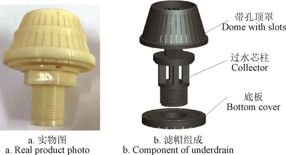
图1 滤帽结构示意图和照片
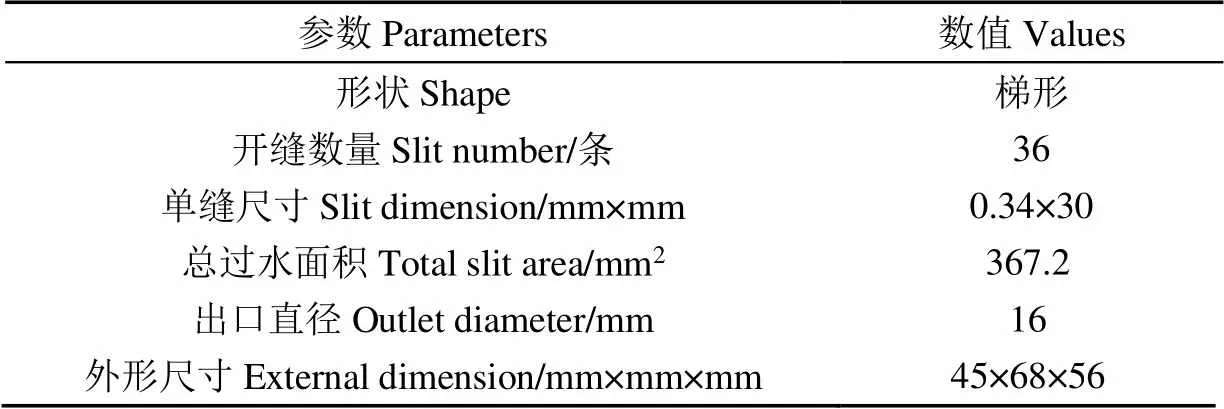
表1 滤帽结构参数
1.2 模型试验
模型试验于2019年9月在中国农科院农田灌溉研究所水力试验大厅进行。采用变频恒压供水方式,管路安装有涡轮蝶阀、流量计进行流速调节和监测,滤柱后装有叠片过滤器(过滤精度120m)收集细小滤料;滤柱模型按实际国产砂石过滤器(砂罐内径600 mm)进行等比例缩放,本试验采用的模型装1个滤帽,实际模型装有滤帽18个,根据流动相似性原理,要保证缩小后模型内通过单滤帽的流量与实际过滤器相同,则模型尺寸(直径、高度)应该按照(1/18)1/3的比例进行缩小[13]。结合市场型号,玻璃管模型直径为220 mm,高800 mm。过滤介质采用石英砂滤料,粒径范围0.85~1.25 mm,滤层厚度为270 mm。滤柱模型装有压力传感器测量各层压力,采用数据采集模块(ADAM-6051)进行实时压力采集。本试验的管路连接如图2所示。
试验分为过滤和反冲洗2个部分,分别对滤帽的水力性能进行测试。首先,采用自来水对单独滤帽进行过滤试验和反冲洗试验,调节蝶阀开度,通过观察电磁流量计读数控制滤层表面速度,根据生产实际,过滤速度范围取0.010~0.040 m/s,在该范围内均匀选择8个滤速工况(0.010、0.015、0.020、0.024、0.028、0.032、0.035、0.040 m/s),待滤速稳定后,记录滤柱最下端两层传感器压力值,从而得到各滤速条件下单独滤帽的水头损失。然后,切换管道连接方式,反向供水,进行单独滤帽反冲洗压降测试。反冲洗流速选择8个工况(0.005、0.010、0.015、0.020、0.025、0.030、0.035、0.040 m/s)。过滤和反冲洗滤速范围较其他学者数值偏大[17-19],主要考虑国内配置滤料粒径普遍偏大导致滤速偏高的应用特点。反冲洗试验结束后,填充当量粒径d为1.08 mm的石英砂滤层,进行正向过滤测试,滤速范围同上。为了保证试验一致性,每次试验开始前首先对滤层冲洗5 min,使滤层充分压实。待滤速稳定后,记录第1层和第4层的压力值,二者差值即为滤层和滤帽总的水头损失。过滤和反冲洗试验均重复3次,取压降平均值作为最终结果。
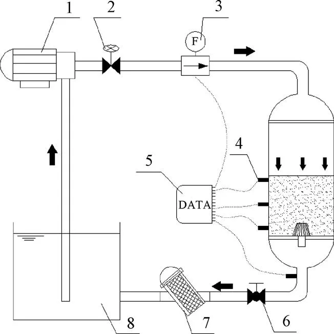
1.离心泵 2.蝶阀 3.流量计 4.压力传感器 5.数据采集模块 6.球阀 7.叠片过滤器 8.水箱
1.Centrifugal pump 2.Butterfly valve 3.Flow meter 4.Pressure sensor 5.Data acquisition module 6.Ball valve 7.Disk filter 8.Water tank
注:图中箭头表示水流流动方向。
Note: The arrow represents the direction of flow.
图2 滤帽水力性能试验布置图
Fig.2 Layout of underdrain hydraulic performance experiment
1.3 滤帽数值模拟设定
1.3.1 模型构建和网格划分
本文以滤帽和周围滤层为模拟对象,采取Pro/E进行滤帽三维建模,分为滤层、滤帽和芯柱3个计算域进行分析各流体域交界面属性设置为Interior。利用ICEM CFD软件,采用四面体非结构化网格对3个计算域进行网格划分,对尺寸小、结构复杂的缝隙部分进行局部加密,如图3所示。
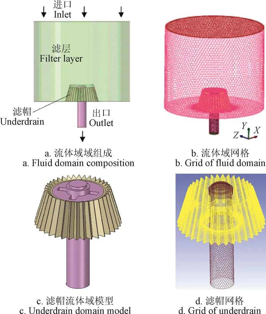
图3 流体域和网格模型
在Fluent(15.0)中将滤层和芯柱网格转换为多面体网格,以提高计算效率。同时,在过滤速度为0.025 m/s条件下进行了网格无关性验证[20],检验指标为进出口压降,得到进出口压降与网格数之间的变化关系如图4所示,可以看出网格数量大于1.8×106后,压降指标趋于稳定,相邻网格密度模拟结果的相对误差值都在3.5%以内,表明网格密度对计算结果的精度影响不大。综合考虑计算精度和计算时间,确定模型网格计算单元总数量为2.41×106。
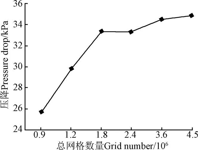
图4 网格无关性检验
1.3.2 模型选择与求解
计算模型的选择取决于水流通过滤层和滤帽的流态。参考文献[21]中滤层雷诺数计算式(1)计算雷诺数Re<2.0时,水流在滤层中的流态为层流。
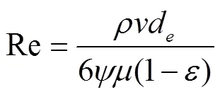
式中为过滤水密度,kg/m3;为流体速度,m/s;d为石英砂滤料当量粒径,取1.08 mm;为石英砂滤料表面积形状系数,取1.16;为流体黏性系数,水的黏性系数为0.001 Pa·s;为滤层孔隙率,取0.43[22]。
由式(1)计算可知,在滤速大于0.008 m/s时,滤层内的雷诺数Re大于2,水流流态均为湍流状态[21]。本试验滤速取值范围内(0.010~0.040 m/s),水流经过滤层时处于湍流状态。水流滤缝部分类似射流发散流动,因此选择Realizable湍流模型进行求解[23],考虑到滤缝附近网格细化处理,选用无滑移壁面边界条件,近壁区采用Scalable壁面函数。
石英砂滤层作为多孔介质设定。多孔介质内流速与压降关系可以用表达式(2)描述[24]。

式中Δ/Δ表示单位滤层高度的水头损失,kPa/m;1/表示黏性阻力系数;2表示惯性阻力系数。
引入系数和,式(2)转换可得到式(3)所示的二次函数关系式。
Δ=+2(3)
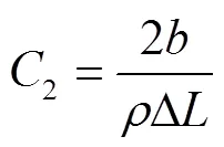
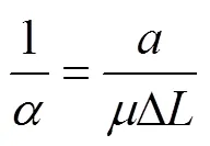
由于滤柱侧壁第1层和第2层压力传感器之间的滤层高度Δ为100 mm,因此,拟合正向过滤时8组过滤速度和压降值Δ,可求得拟合系数和,根据式(4)和式(5),可计算得到多孔介质黏性阻力系数1/和惯性阻力系数2。计算结果:1/=1.52×109,2=66 545,由此在Fluent中定义多孔介质过滤模型相关参数。在反冲洗时,滤层膨胀属于多相流模拟,且滤层膨胀不影响滤帽本身的水损变化,因此反冲洗模拟不考虑顶部滤层,仅模拟单独滤帽。
计算过程中,采用低松弛迭代的变松弛系数法,压力速度耦合方程采用PC-SIMPLE算法。过滤状态下进口边界为速度入口,垂直滤层顶部界面,取如前所述0.010~0.040 m/s之间的8个工况。出口边界为压力出口,因为本研究只关注进出口压差变化值,出口压力设定值与实际模型试验相同,取出口压力为0.1 MPa。
2 结果与分析
2.1 模型验证结果
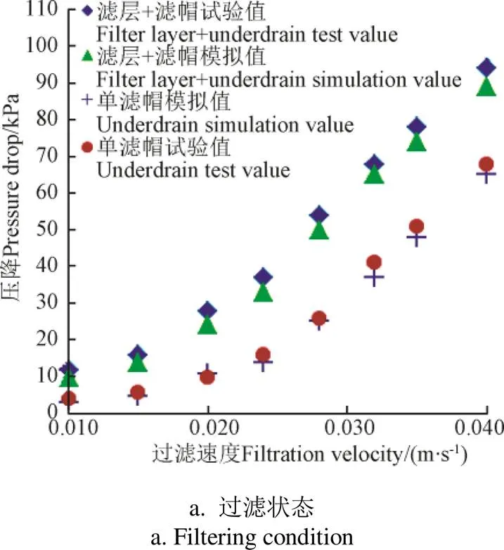
通过试验得到不同速度下的滤帽和滤层水头损失变化关系,并与模拟值进行了对比,从图5可知,模型试验实测的单独滤帽、滤帽+滤层的水头损失结果和CFD模拟计算结果的变化趋势基本相同,水头损失试验值较数值模拟值偏大,主要是因为压力传感器取样位置相对靠下,产生了部分额外水头损失,主要是因为压力传感器取样位置相对靠下,产生了部分额外水损,但二者相对误差为3.54%~6.53%,小于10%,说明所选模型及参数合理[20]。
2.2 滤帽水头损失分布特性分析
图6为不同滤速条件下的滤帽和滤层压降比(即滤帽或滤层压降占总压降的比例,%)分布,可以看出,在过滤状态下,滤速小于0.024 m/s时,滤层产生的压降高于滤帽;在滤速等于0.024 m/s时,滤帽和滤层产生的压降分别为15和18 kPa,随着过滤速度的增大,滤帽产生的水头损失增加更为明显,在滤速为0.040 m/s时,滤帽产生的压降为68 kPa,占滤帽和滤层全部压降的72.3%。从图4也可以看出,对同一滤帽,正向过滤和反向反冲洗的水头损失是不同的,在流速低于0.030 m/s时,反冲洗状态下的滤帽水损要高于过滤状态。
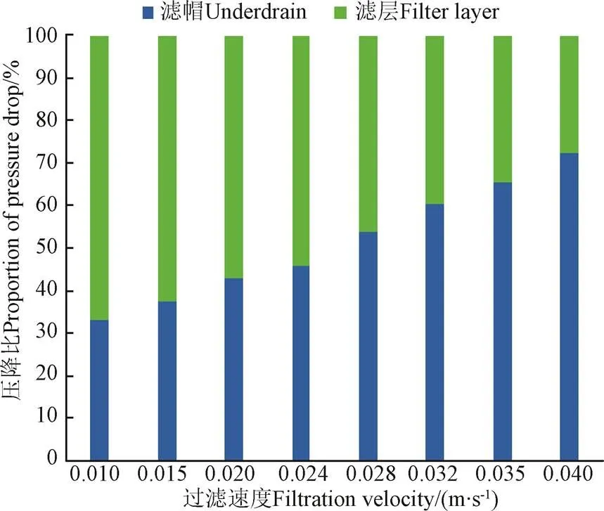
图6 不同过滤速度条件下实测压降比分布
通常砂石过滤器内滤帽数量一般为十几甚至更多,因此,滤帽产生的水头损失不可忽视。生产实际中,过滤器选型不当,就会导致砂石过滤器在高滤速条件下超负荷运行,由此产生的滤帽水损更大。因此,注重过滤器选型,选择水损较小的滤帽,能够大大降低整个系统能耗损失。
2.3 基于模拟结果的滤帽水力特性分析
2.3.1 外部流动特性分析
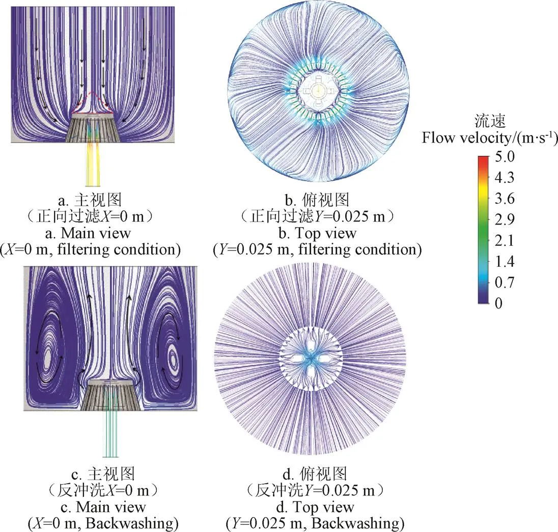
图7为正向过滤滤速0.035 m/s和反冲洗速度0.015 m/s条件下的流线图。过滤状态下,水流通过滤层后,水流收缩进入滤缝,经过滤帽腔体后再次收缩,进入芯柱,因此,水流存在先收缩、后扩大、再收缩的变化过程,速度逐步增加。从图7a中流线可以看出,水流在逐步收缩过程中,没有明显边界层分离现象,只在滤帽内边角处有较小的漩涡产生,流线属于均匀收缩,因此水头损失较小;而反冲洗过程时,压缩水流突然扩大后形成较大的漩涡区,产生的水头损失也更大。漩涡高度随反冲洗速度不同,在25~40 cm之间变动,反冲洗速度越高,紊动强度越大,漩涡尺度越小,一定程度上反映了滤层的翻腾状态。
由图7b可知,本研究的模拟滤帽顶部平面为实体结构,没有过水缝隙,滤帽顶部水流在接近滤帽时,轴向速度转为水平速度,水流绕过顶面从侧面进入滤帽,增加了流动的不稳定性,降低了过水效率,同时滤帽顶板部分受力加大,需要芯柱加强筋的支撑,才能防止滤帽损坏;在反冲洗时,在滤帽顶部正上方存在一定范围的流动稳定区域,湍动强度较小,对于滤料的反冲洗是不利的。供试滤帽顶板实体面积为310 mm2,根据表1中顶罩表面开孔比例,顶板可新增过水面积约65 mm2,因此若将顶部设计为缝隙结构,较初始过水面积(367.2 mm2)能够增加17.7%过水面积,有助于提高过水效率。
注:正向过滤速度0.035 m·s-1,反冲洗速度0.015 m·s-1。
2.3.2 内部流动特性分析
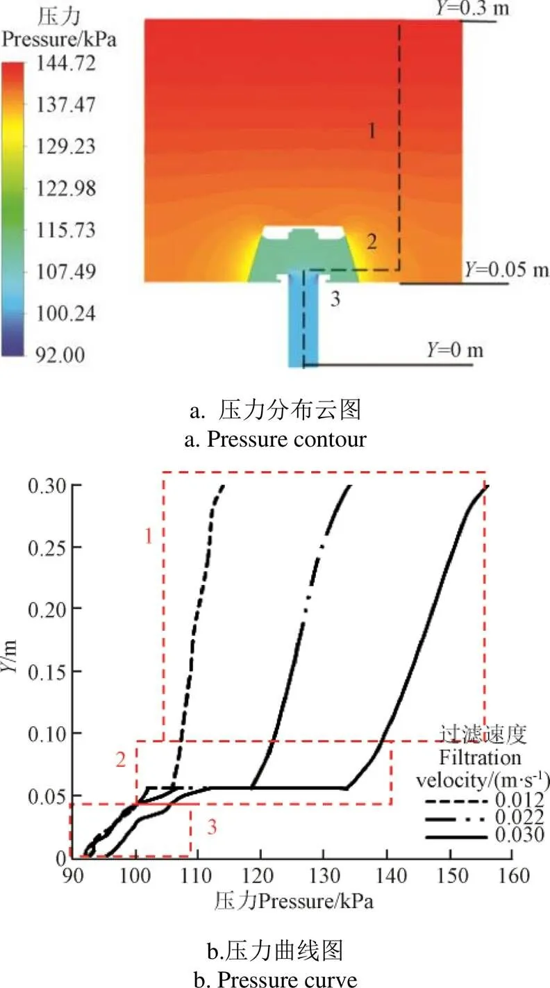
流阻特性是滤帽内部流动的外在表现,是评价滤帽的主要性能参数。由试验数据,能够得出滤层和滤帽两部分的水损分布规律,而滤帽周围近滤缝区域和滤帽内部的局部压降规律,则需借助数值模拟进行分析。图8a为0.030 m/s过滤速度条件下的压力变化云图。从中可以看出压力变化显著的区域为近滤缝区和芯柱顶部入口处,因此可以将滤层至滤帽出口范围分成3个区域:介质滤层区1、近滤缝区域2和滤帽芯柱3。为了分析这3个区域内压力随过滤速度的变化规律,沿着图8a中的虚线,提取各沿程点的压力值,绘制图8b所示0.012、0.022和0.030 m/s 3种过滤速度下,方向沿程各点压力曲线。从图8b中可以看出,过滤速度越大,各沿程点的压力值越高。速度越高,各区域内曲线斜率越小,代表该区域内压降越大。在滤速为0.012 m/s时,区域1产生的压降为6 kPa,区域2为7 kPa,区域3为9 kPa;而在滤速为0.030 m/s时,区域1产生的压降为16 kPa,区域2为32 kPa,区域3为12 kPa。比较2种滤速下的压降分布可知,随着滤速增加,滤层压降占比逐渐降低,而滤帽及周围区域产生的水损升高明显。在近滤缝区域2,压降变化明显,主要是因为水流在滤帽表面附近聚集,以较大滤速通过滤帽周围局部滤层,由式(2)可知,局部滤层水损是的二次函数,通过图7a速度矢量图可知水流进入滤缝的瞬时速度达到了2.57 m/s,滤速的急剧增加导致滤缝附近局部区域的水损显著增加。由此可知,通过增加滤缝数量,扩大滤帽与滤层接触面积,在滤帽周围采用大粒径滤料填充,都有助于降低局部水头损失。
注:1、2、3分别代表介质滤层区、近滤缝区域、滤帽芯柱。
为了分析滤帽芯柱区域3内的压力变化规律,对芯柱内局部流场进行了分析。图9为3种滤速条件下滤帽内部速度分布云图,可以看出芯柱进口处滤速最高达到4.01 m/s,远远高于滤缝处速度。由于梯形滤帽的芯柱顶部有4个支撑筋,导致芯轴内形成了较大的绕流波动旋涡,水流绕过芯柱后,水平流动转为轴向流动,且由于芯柱内径骤然缩小,水流在芯柱中心处形成对撞扰动,产生了较大的流动阻尼和能量损失,因此芯柱内横截面上压力分布是不均匀的,如图10所示。在向下流动过程中,水流逐步混合,由于芯轴出口尺寸较小,附壁效应显著,芯柱中心轴处压力最高,流速最快,慢慢整个截面流速趋于均匀。因此,可以通过改变芯轴支撑筋形式、增加出水口尺寸来提高过水效率,降低芯轴水损。
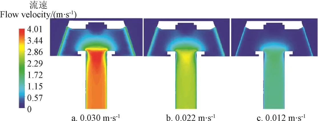
图9 不同过滤速度下滤帽内部流速分布云图
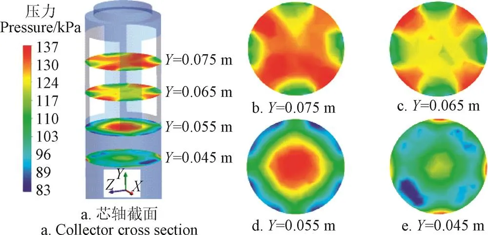
图10 芯柱内部不同截面压力分布云图
2.4 滤帽优化分析
根据以上分析可知,影响滤帽水阻特性的主要因素包括滤缝布局、开缝面积和芯柱结构及出口大小等。现有梯形滤帽结构是针对工业水处理厚滤层、慢滤池设计[25-26],而农业微灌砂石过滤通常是浅滤层、快滤速过滤模式[27-28],因此,针对当前常用的梯形滤帽水损较大,运行能耗较高的特点,针对农业砂石过滤器,参照文献[29],本研究设计了一种扁平球面滤帽(见图11),并采用Ansys Fluent软件模拟了过滤状态和反冲洗过程中球面扁平滤帽(参数设定同1.3.2节)流速分布特性,如图12所示。
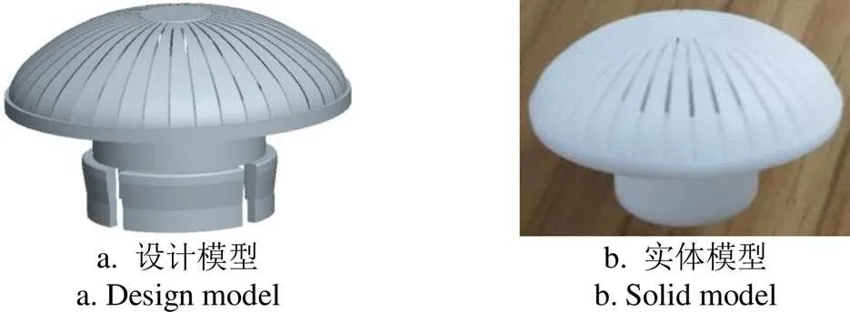
图11 改进滤帽结构模型示意图
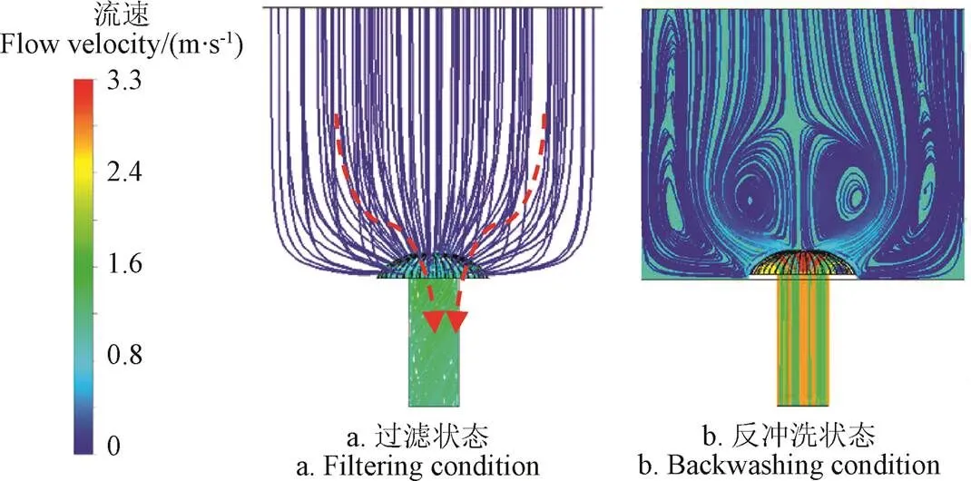
注:正向过滤速度0.030 m·s-1,反冲洗速度0.015 m·s-1。
由图11所示,本研究设计的滤帽,缩小了滤帽的高宽比,取消了滤帽顶部实体平面区,采用了顶面全开缝设计。滤缝宽度为0.34 mm,长度为39.5 mm,单滤帽开孔36条,总过水面积较原梯形滤帽增加了27%,同时芯柱出口扩大为30 mm,且采用承插式出口,安装和检修更便捷。从图12a可以看出,滤帽过水流线更流畅均匀,水流通过滤帽的沿程平均距离降低了14%,并且流线弯折显著减少,而从图12b可以看出,反冲洗时水流形成的漩涡更小、更密集,有助于增加滤层滤料的翻转频率,利于杂质的脱落和排出。具体改进参数和应用效果将进一步开展试验进行探讨。
3 结 论
本文以微灌砂石过滤器滤帽为研究对象,采用不同的过滤速度和反冲洗速度,对滤层和滤帽流阻特性进行了试验测试和数值模拟,分析了滤帽内外的压降特性和滤帽结构对内部流场的影响规律,具体结论如下:
1)采用数值模拟的方法进行滤帽水力特性分析,能够较好反映实际滤帽水损变化规律,相对误差为3.54%~6.53%,模拟结果基本可信,可以为后续滤帽结构改进和优化提供数据支撑。
2)过滤状态下,低速运行时,滤层水损占主要部分,而在滤速大于0.024 m/s时,滤帽产生的水头损失占比逐步扩大,滤速为0.040 m/s时,滤帽产生的水损占全部水损的72.3%,因此要重视过滤器选型,选择水损较小滤帽,避免系统超负荷运行,增加能耗。
3)反冲洗状态下产生的水头损失较过滤状态更高,主要是因为反冲洗时存在漩涡区,增加了水损,且反冲洗速度越高,漩涡尺度越小。
4)滤帽顶部实心结构影响了过滤状态下的水流通过效率,在反冲洗时,滤帽顶部存在稳定区,不利于滤料清洗,采用顶部开缝结构,可以增加17.7%过水面积。
5)滤帽水损主要产生于近滤缝区域和芯柱区域,均是由于过水流道突然缩小导致,在滤层滤速为0.030 m/s时,滤缝和芯柱进口处滤速分别为2.57和4.01 m/s,可通过优化芯柱支撑筋和扩大芯柱出口直径,改善滤帽内部流阻过高问题。
6)根据以上分析结果,针对农业快滤模式,设计了一种扁平球面新型滤帽,并进行了过滤和反冲洗数值模拟,滤帽的过滤水损更小,反冲洗产生的漩涡更小、分布更均匀,更有利于滤层均匀、频繁的翻转摩擦,有助于提高反冲洗效率。
本文主要研究了单个滤帽的内部流场分布特征,不足之处:由于滤帽通常为阵列式布置,多个滤帽之间的流场会存在相互影响,从而影响过滤器的清洁压降和反冲洗效率。因此后续工作中将进一步分析多个滤帽的组合流场分布。
[1] 李久生,栗岩峰,王军,等. 微灌在中国:历史、现状和未来[J]. 水利学报,2016,47(3):372-381.
Li Jiusheng, Li Yanfeng, Wang Jun, et al. Microirrigation in China: history, current situation and prospects[J]. Journal of Hydraulic Engineering, 2016, 47(3): 372-381. (in Chinese with English abstract)
[2] Deus F A P D, Mesquita M, Camilo J, et al. Hydraulic characterisation of the backwash process in sand filters used in micro irrigation[J]. Biosystems Engineering, 2020, 192: 188-198.
[3] Bove J, Pujol J, Arbat G , et al. Environmental assessment of underdrain designs for a sand media filter[J]. Biosystems Engineering, 2018, 167: 126-136.
[4] 王新坤,许颖,涂琴. 微灌系统过滤装置优化选型与配置[J]. 农业工程学报,2011,27(10):160-163.
Wang Xinkun, Xu Ying, Tu Qin. Optimal selection and collocation of filter unit in micro-irrigation system[J]. Transactions of the Chinese Society of Agricultural Engineering (Transactions of the CSAE), 2011, 27(10): 160-163. (in Chinese with English abstract)
[5] Tarjuelo J M, Rodriguez-Diaz J A, Abadía R, et al. Efficient water and energy use in irrigation modernization: Lessons from Spanish case studies[J]. Agricultural Water Management, 2015, 162: 67-77.
[6] 牛文全. 微压滴灌技术理论与系统研究[D]. 杨凌:西北农林科技大学,2006.
Niu Wenquan. Theory and System Research of Micro Pressure Drip Irrigation Technology[D]. Yangling: Northwest A&F University, 2006. (in Chinese with English abstract)
[7] 李云开,冯吉,宋鹏,等. 低碳环保型滴灌技术体系构建与研究现状分析[J]. 农业机械学报,2016,47(6):83-92.
Li Yunkai, Feng Ji, Song Peng, et al. Developing situation and system construction of low-carbon environment friendly drip irrigation technology[J]. Transactions of the Chinese Society for Agricultural Machinery, 2016, 47(6): 83-92. (in Chinese with English abstract)
[8] Burt C M. Hydraulics of commercial sand media filter tanks used for agricultural drip irrigation[R]. ITRC Report No.R10001. San Luis Obispo, California: Irrigation Training and Research Center, 2010.
[9] Mesquita M, Testezlaf R, Deus F, et al. Design and hydrodynamic performance testing of a new pressure sand filter diffuser plate using numerical simulation[J]. Biosystems Engineering, 2019, 183: 58-69
[10] Bové J, Arbat G, Pujol T, et al. Reducing energy requirements for sand filtration in microirrigation: Improving the underdrain and packing[J]. Biosystems Engineering, 2015, 140: 67-78.
[11] Mesquita M, Testezlaf R, Ramirez J C S. The effect of media bed characteristics and internal auxiliary elements on sand filter head loss[J]. Agricultural Water Management, 2012, 115(115): 178-185.
[12] Pujol T, Arbat G, Bové, et al. Effects of the underdrain design on the pressure drop in sand filters[J]. Biosystems Engineering, 2016, 150: 1-9.
[13] Arbat G, Pujol T, Puig-Bargu J, et al. An experimental and analytical study to analyze hydraulic behavior of nozzle-type underdrains in porous media filters[J]. Agricultural Water Management, 2013, 126: 64-74.
[14] 沈倩. 气水反冲洗滤头的水力学特性研究[D]. 西安:西安建筑科技大学,2014.
Shen Qian. Study of Fluid Mechanics Characteristics of Filter Head Air-water Backwashing[D]. Xi’an: Xian University of Architecture and Technology, 2014. (in Chinese with English abstract)
[15] 刘文娟. 石英砂滤层过滤与反冲洗特性的实验研究及数值模拟[D]. 北京:中国农业科学院,2014.
Liu Wenjuan. Experimental Study and Numerical Simulation of Filtration and Backwashing with Quartz-sand Filters[D]. Beijing: Chinese Academy of Agricultural Sciences, 2014. (in Chinese with English abstract)
[16] Pietro C , Roberto T, Fabio, et al. Characterization of flow lines generated by pressurized sand filter underdrains[J]. Chemical Engineering Transactions, 2017, 58: 715-720.
[17] Bové J, Arbat G, Duran-Ros M, et al. Pressure drop across sand and recycled glass media used in micro irrigation filters[J]. Biosystems Engineering, 2015, 137: 55-63.
[18] 张文正,翟国亮,吕谋超,等. 微灌条件下三种过滤器过滤效果试验研究[J]. 灌溉排水学报,2017,36(4):88-93.
Zhang Wenzheng, Zhai Guoliang, Lyu Mouchao, et al. Experimental study on the efficacy of sand filter, screen filter and disc filter for removing silts from the Yellow River water for micro-irrigation[J].Journal of Irrigation & Drainage, 2017, 36(4): 88-93. (in Chinese with English abstract)
[19] 董文楚. 滴灌用砂过滤器的过滤与反冲洗性能试验研究[J]. 水利学报,1997,28(12):72-78.
Dong Wenchu. A study on the filtration and backflushing performance of the filters with crushed quartz sand for drip-irrigation[J]. Journal of Hydraulic Engineering, 1997, 28(12): 72-78. (in Chinese with English abstract)
[20] 张春晋,孙西欢,李永业,等. 螺旋流起旋器内部流场水力特性数值模拟与验证[J]. 农业工程学报,2018,34(1):53-62.
Zhang Chunjin, Sun Xihuan, Li Yongye, et al. Numerical simulation and verification of hydraulic characteristics of internal flow field in spiral flow generator[J]. Transactions of the Chinese Society of Agricultural Engineering (Transactions of the CSAE), 2018, 34(1): 53-62. (in Chinese with English abstract)
[21] 李景海,刘清霞,黄修桥,等. 微灌石英砂滤层流态特性与分形阻力模型参数确定[J]. 农业工程学报,2015,31(13):113-119.
Li Jinghai, Liu Qingxia, Huang Xiuqiao, et al. Flow state characteristics and fractal model parameters determination of quartz sand filter layer used in micro-irrigation[J]. Transactions of the Chinese Society of Agricultural Engineering (Transactions of the CSAE), 2015, 31(13): 113-119. (in Chinese with English abstract)
[22] 翟国亮,陈刚,赵红书,等. 微灌用均质砂滤料过滤粉煤灰水时对颗粒质量分数与浊度的影响[J]. 农业工程学报,2010,26(12):13-18.
Zhai Guoliang, Chen Gang, Zhao Hongshu, et al. Effects of filter with uniform sandy filtration medium used in micro-irrigation on mass fraction of particles and turbidity of water with fly ash[J]. Transactions of the Chinese Society Agricultural Engineering(Transaction of the CSAE), 2010, 26(12): 13-18. (in Chinese with English abstract)
[23] Ansys Inc. ANSYS FLUENT User′s Guide Release 19.0[M]. Pittsburgh: ANSYS Inc, 2018.
[24] 张建锋. 均质滤料直接过滤的模拟和计算[D].西安:西安建筑科技大学,2001.
Zhang Jianfeng. Simulation and Calculation of Direct Filtration with Uniform Filter Media[D]. Xi′an: Xian University of Architecture and Technology, 2001. (in Chinese with English abstract)
[25] 周超. 深床过滤对水中颗粒物截留效果的实验研究[D]. 西安:西安建筑科技大学,2014.
Zhou Chao. Effects on Particle Retention in Water of Deep Bed Filtration[D]. Xi′an: Xian University of Architecture and Technology, 2014. (in Chinese with English abstract)
[26] 曹相生,刘杰,孟雪征,等. 滤层厚度对慢滤池深度处理污水的性能影响[J]. 生态环境学报,2010,19(3):566-569.
Cao Xiangsheng, Liu Jie, Meng Xuezheng, et al. Experimental study of the filter bed depth on performances of a slow sand filter used for wastewater advanced treatment[J]. Ecology and Environmental Sciences, 2010, 19(3): 566-569. (in Chinese with English abstract)
[27] Elbana M, Ramrez F, Cartagena, et al. Effectiveness of sand media filters for removing turbidity and recovering dissolved oxygen from a reclaimed effluent used for micro-irrigation[J]. Agricultural Water Management, 2012, 111: 27-33.
[28] 张杰武,冯吉,徐飞鹏,等. 引黄滴灌砂石过滤器滤料过滤性能[J]. 排灌机械工程学报,2016,34(4):357-361.
Zhang Jiewu, Feng Ji, Xu Feipeng, et al. Sand filter performance on drip irrigation with the Yellow River[J]. Journal of Drainage and Irrigation Machinery Engineering, 2016, 34(4): 357-361. (in Chinese with English abstract)
[29] Bové J, Puig-Bargu J, Arbat G, et al. Development of new underdrain for improving the efficiency of microirrigation sand media filters[J]. Agricultural Water Management, 2017, 179: 296-305.
Hydraulic performance experiment and internal flow field numerical simulation for underdrain of micro-irrigation sand filter
Cai Jiumao, Zhai Guoliang※, Lyu Mouchao, Liu Jieyun, Zhang Wenzheng
(,/453002)
Sand filter is considered to be one of the best choice to prevent clogging in micro-irrigation system. Head losses in media filter are produced by the friction loss due to the internal auxiliary elements of the filter container and the resistance offered by the media layer. The underdrain element is a core component in sand filter. To deeply understand the hydraulic behavior of underdrain, the experimental and numerical investigations were conducted to explore the flow resistance characteristics and flow field distribution in the underdrain. Laboratory experiments of filtering and backwashing were conducted in Farmland Irrigation Research Institute, Chinese Academy of Agricultural Sciences, Xinxiang, China. A trapezoidal underdrain element applied commonly in domestic market was selected in the experiment. It was installed in a scaled sand filter based on a commercial filter with 600 mm internal diameter. The sand filter model were tested at eight filtering velocities ranging from 0.010 to 0.040 m/s, and eight backwashing velocities ranging from 0.005 to 0.040 m/s, which were consist with the actual commercial filter operation. The experimental variables were monitored in real time by a data acquisition system consisted of a flowmeter and pressure transmitter. The internal flow behavior through the filter was simulated using the Computational Fluid Dynamics (CFD) method. A CFD model of the underdrain was developed by ANSYS Fluent 15.0. The geometry of the underdrain and its unstructured mesh were designed by ICEM software. Due to the turbulent flow regime in the underdrain and layer, the realizable k-ε turbulence model and the porous medium model were selected for solution. The computing area and the boundary condition of inlet and outlet were proposed. To ensure the reliability of the numerical simulation, the experimental values were compared with the simulated results. The results showed that the simulated values of head loss were in good agreement with the experimental values with the relative errors between 3.54% and 6.53%. The tested results showed that as the filtering velocity increased (>0.024 m/s), the pressure drop produced by the underdrain improved more significantly than the media layer. When the velocity increased to 0.040 m/s, the 72.3% of the pressure drop were produced by the underdrain. At the same filtration velocity, the pressure drop of backwashing mode was higher than filtering mode. The results confirmed that it was important to select appropriate filter model and avoid overload operation for the irrigation system. The simulated pressure and velocity contours showed that the structure without slots at the top of underdrain increased the non-uniformity of the flow streamlines and affected the backwash efficiency. Due to the narrowing of the flow section gradually from the layer to the underdrain outlet, the flow velocity increased drastically. When filtration velocity was 0.030 m/s, the velocities at the narrow slots and the entrance of the collector reached 2.57 and 4.01 m/s, respectively, resulting in significant pressure drop in the two region subsequently. The pressure contours of the collector at different cross sections showed non-uniformity due to the violent disturbance of the flow. In view of these results, a spherical flat underdrain with smaller aspect ratio and more uniform slots distribution was designed. Compared to the trapezoidal underdrain, the distance of the flow through the underdrain decreased by 14% and the passing area increased by 27%. In addition, the diameter of the tube outlet increased to 30 mm. The modification favored vertical flow through the porous medium and the underdrain chamber with a more direct exit, thereby reducing pressure drop. The CFD simulations of the modified underdrain showed the smoother streamline around the underdrain for filtering mode and a smaller vortex scale for backwashing mode, indicating excellent passing capacity and backwash efficiency. The study could guide the design of filter for irrigation equipment manufacturer, irrigation project designer and field operator.
flow velocity; filters; hydraulic performance; micro-irrigation; sand media filter; underdrain element; flow field simulation; flow resistance characteristic
蔡九茂,翟国亮,吕谋超,等. 微灌砂石过滤器滤帽水力性能试验及内部流场模拟[J]. 农业工程学报,2020,36(13):67-74.doi:10.11975/j.issn.1002-6819.2020.13.008 http://www.tcsae.org
Cai Jiumao, Zhai Guoliang, Lyu Mouchao, et al. Hydraulic performance experiment and internal flow field numerical simulation for underdrain of micro-irrigation sand filter[J]. Transactions of the Chinese Society of Agricultural Engineering (Transactions of the CSAE), 2020, 36(13): 67-74. (in Chinese with English abstract) doi:10.11975/j.issn.1002-6819.2020.13.008 http://www.tcsae.org
2020-03-18
2020-05-23
河南省科技攻关项目(2019-288);中国农业科学院基本科研业务费(Y2018PT72、FIRI2017-25、FIRI202002-01)
蔡九茂,博士生,主要从事微灌技术理论与应用研究。Email:caijiumao@163.com
翟国亮,博士,研究员,博导,主要从事微灌技术理论与应用研究。Email:zhai3393@126.com
10.11975/j.issn.1002-6819.2020.13.008
S275.5
A
1002-6819(2020)-13-0067-08
