Two-dimensional piston pump: Principle, design,and testing for aviation fuel pumps
2020-06-11TongXINGYezhouXUJinRUAN
Tong XING, Yezhou XU, Jin RUAN,*
a Key Laboratory of Special Purpose Equipment and Advanced Manufacturing Technology Ministry of Education,Zhejiang University of Technology, Hangzhou 310018, China
b The State Key Laboratory of Fluid Power and Mechatronic Systems, Hangzhou 310027, China
KEYWORDS Fuel pumps;Kinematics - design;Mechanical design;Structure design;Two-dimensional piston pumps
Abstract Aviation fuel pumps of the future are required to be highly efficient and lightweight.As such, this work presents the designs of various mechanisms and structures of advanced twodimensional piston pumps for aero-engines, and their universal kinematic design methods are detailed herein.The efficiency of various piston pump prototypes was experimentally tested at various speeds in an open circuit.The experimental results indicate that two-dimensional piston pumps have a volumetric efficiency >91% and a higher power-mass ratio than conventional fuel pumps under all the conditions studied. Furthermore, the structural and material problems encountered during testing can provide a blueprint for further improvement of the design and processing of two-dimensional piston fuel pumps.
1. Introduction
Fuel pumps are key components of aero-engines. Axial piston pumps are frequently used as the fuel pump in high-pressure fuel systems, whereas gear pumps are used in moderatepressure fuel systems because of their higher fuel adaptability.However,owing to the low viscosity,poor lubricity,low cleanliness, strong permeability, and high corrosiveness of aviation kerosene, fuel pumps face a multitude of problems, including poor sealing capabilities and decreased efficiency because of the quick wearing of the main friction pairs.1
In recent years, centrifugal-gear combined pumps have been used widely in aero-engines under moderate pressure.Centrifugal and gear pumps both have a simple structure,low volume, low weight, and long life, making them suited for adverse application conditions,thereby enabling them able to be used as a booster and main fuel pump, respectively.
Improving the speed and efficiency of aviation fuel pumps is the main objective of technological progress. In combined fuel pumps, centrifugal booster pumps can work at high speeds, but gear pumps cannot match higher speeds.2This is due to three main reasons: (i) at high speeds and pressures>10 MPa, the increased PV value increases the complexity of the sliding bearing design, (ii) the higher flow ratio(Qmax/Qmin) and lower expected back-flow temperature complicates the back-flow structure design, and (iii) effects of gas cavitation.3,4
Electromotion fuel pumps will likely be core components of future distributed-control aero-engines.5. The United States and United Kingdom have made great progress in the research of multi-electric distributed-control aero-engine technology;as such, multi-electric distributed control aero-engines are predicted to reach an experimental prototype stage by 2020.5Variable-speed combined fuel pumps can be powered by variable-frequency, high-speed, and low-inertia motors, and their fuel flow rate meets the needs of the engine by adjusting the motor speed; further, the fuel regulator is not needed.Thus, next-generation fuel pumps should provide higher efficiency under variable rotating speeds.
On the whole, fuel pump technology is similar to that of hydraulic pumps. Continuous technological progress has been made in the local design,micro-structure, and friction pairs of traditional hydraulic pumps.6-13To date, most researchers have focused on improving the volumetric efficiency of fuel pumps of traditional types. However, to meet the advanced requirements of the main fuel pump, structural innovation is necessary.
The invention of a two-dimensional piston pump by Prof.Ruan Jian in 2014 and shown in Fig. 1 has reinvigorated research into the field.14The structure of this twodimensional piston pump is completely different than other displacement pumps,such as piston pumps,gear pumps,screw pumps,and vane pumps.15Unlike the multiple sliding friction pairs in traditional axial piston pumps,two-dimensional piston pumps contain only two rolling friction pairs, making it more suitable to the advanced technical requirements of the main fuel pump.
This study aims to focus on the crucial innovative design problems of two-dimensional piston pumps by developing and testing prototypes.

Fig. 1 Original design of a two-dimensional piston pump.16.
2. Principle
The structure of a basic two-dimensional piston pump unit is illustrated in Fig.2.Here,the piston group comprises a special piston and two shafts on each side with two rollers attached to each end of the shafts. Two curved, saddle-shaped tracks are arranged on either side of the cylinder to provide piston support. The two-point line between the highest point of the left track and lowest point of the right track is parallel to the piston axis, as is the two-point line between the lowest point of the left track and highest point of the right track. These two tracks and piston groups compose the motion conversion mechanism. The two displacement chambers on either side of the piston comprise a cylinder (distributor) that is precisely fit to the piston and a sliding ring that is precisely fit to the piston shafts. The piston has four distributing slots arranged circumferentially;slots ①and ③open into the left displacement chamber and slots ②and ④open into the right displacement chamber. Correspondingly, the cylinder has four openings connecting to the distributing slots. Thus, the cylinder acts as a distributor, and the distributing function is performed by the special piston and cylinder.
In a two-dimensional pump,the pump shaft is connected to the piston through a two-dimensional coupling. As the piston shafts rotate at the angular velocity ω, the motion conversion mechanism causes the piston to do the reciprocating motion under the track support, where Hkis the piston stroke; i.e.,the drive motion is the rotational motion and the reciprocating motion is the following motion.
As the volume of the left chamber increases, the fluid is pulled through inlet openings and slots ①and ③.Meanwhile,the fluid in the right chamber is pushed through outlet openings and slots ②and ④. Because the curved track has two peaks,the piston will reciprocate two times per rotation,causing the fluid to flow out of the pump two times for each displacement chamber. Thus, each rotation allows for four piston strokes.
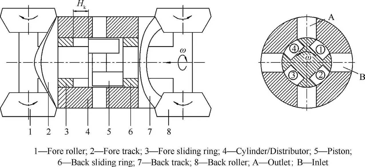
Fig. 2 Schematic of a basic unit of two-dimensional piston pumps.
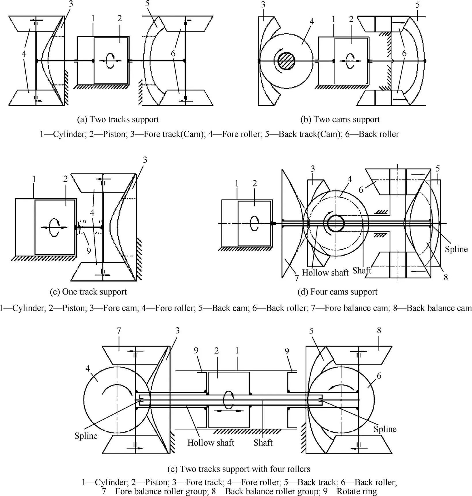
Fig. 3 Kinematic scheme of a two-dimensional piston unit.
Given this design,two-dimensional piston pumps and traditional piston pumps have three significant differences. First,the special piston with two rods on each end is driven by a symmetrical two-dimensional motion conversion mechanism.Here, the force on piston is along its axis, unlike the angular force seen in traditional piston pumps. Second, the motion conversion mechanism used in the two-dimensional piston pump is a two-dimensional higher-pair mechanism that causes one piston’s reciprocating movement while rollers turn along a ring-shaped space contour,whereas the constraint component(e.g., swash plate or stroke ring) is large in traditional piston pumps and is suitable for multiple pistons. Third, during fluid distribution,the fluid is guided by the piston slots to the openings on the cylinder through piston rotation in the twodimensional piston pump design; this distributing structure is different from the control journal in radial piston pumps.Among these three differences, the motion conversion mechanism represents the core of the novelty of the two-dimensional piston pump.
3. Mechanism design
Numerous motion conversion mechanisms are drawn as mechanism sketches in Fig.3.Among them,the mechanisms shown in Fig. 3(a)-(c), are designed in previously developed twodimensional piston pumps,16-20the mechanisms shown in Fig.3(d)and(e),are newly proposed in this study.Here,these mechanisms can be divided into two types.
(a) A two-dimensional piston pump with track support,where the two curved tracks remain stationary and the rollers connected to the piston rotate along the track,as shown in Fig. 3(a), (c), and (e).
(b) A two-dimensional piston pump with cam support,where the two roller shafts remain stationary and the cams fixed to the piston rotate to push the piston into linear motion, as shown in Fig. 3(b) and (d).
In Fig. 3(a) and (b), the piston and cylinder are between 2 two-dimensional higher pair mechanisms, where the piston is alternately driven from both sides and has enough rigidity support for high-speed rotation. In Fig. 3(c) and (d), the piston and cylinder are placed on one side of the motion conversion mechanism,which provides cartridge structure and lubrication but reduces the rigidity of piston support, thus making it unsuitable for high-speed rotation.
Because the piston group has a larger mass than a single piston, and the piston performs the reciprocating motion two times per rotation,a greater inertial force is exerted on it than that acting on the piston in traditional piston pumps.Furthermore, high rotational speeds may cause the inertial force to exceed the hydraulic force. Thus, an inertia balance must be considered during the design of high-speed pumps.
In Fig.3(d),components 7 and 8 represent a pair of balance cams attached to a hollow shaft connected to the piston shaft with splines. Roller 4 contacts both cam 3 and cam 7; at the given position, cam 3 is at the lowest position and cam 7 is at the highest position. Similarly, roller 6 contacts both cam 5 and cam 8;at the given position,cam 8 is at the lowest position and cam 5 is at the highest position. Thus, the balance cams(cams 7 and 8)move in the opposite direction as the piston,thereby partially balancing the inertial force of the piston group.
The second inertial force balance mechanism is shown in Fig.3(e).In this figure,the piston and rollers 4 and 6 are fixed on the shaft marked the hollow shaft;rotate rings 9 and roller 7,roller 8 are fixed on two shafts that covered the hollow shaft at each ends; these three shafts connect together via two splines.Rollers 4 and 7 contact track 3 at the highest and lowest positions,respectively,whereas rollers 6 and 8 contact track 5 at the lowest and highest positions,respectively.Therefore,if the piston turns according to the phase shown in Fig.3(e),the piston will move to the right, and ring 9 will move to the left.Similarly,the balance roller group,including components 7,8,and 9, balances the inertial force of the piston group. This design also allows the operation chamber to change twice during a single piston stoke, i.e., the pump has two times the displacement of the pump in Fig. 3(a) if the piston diameter and stroke are the same.
4. Kinematic design
4.1. Motion law of piston

Fig.4 Kinematic parameters as dependent on angular position θ.
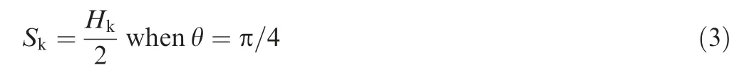
As the motion conversion mechanism is a type of twodimensional higher-pair mechanism, the follower motion can be designed according to a variety of motion-law expressions,such as equal acceleration and deceleration, sine or cosine acceleration, or trapezoidal acceleration. Fig. 4 illustrates the equal acceleration and deceleration motion law:equal acceleration akis set in the first half stroke in the displacement Skand equal deceleration akis set in the second half stroke, and the velocity vkget to the maximum value at the piston rotate angle π/4 or 3π/4, 5π/4, 7π/4.
If a piston was designed using the equal acceleration and deceleration motion law, the instantaneous flow rate q of the two-dimensional piston pump with one piston can be described as a triangular wave pattern,as shown in Fig.5(a).If two basic units shown in Fig. 2 are connected in series by twodimensional coupling with a phase difference of π/4, the instantaneous flow rate should remain constant, as shown in Fig. 5(b).
Furthermore, if the two-dimensional pump comprises multiple basic units, the reciprocating motion law of the piston is best as equal acceleration and deceleration motion law,and the number of pistons is even. Moreover, it is relatively easy to design the surface profile and manufacture for the track or cam according to this law.
The piston was thus designed according to the equal acceleration law. As such, the piston group rotates at a constant angular velocity ω around its own axis. As shown in Fig. 2,the position is at right dead position. The displacement of the piston Skis expressed as follows:

where akis the piston acceleration,t is time,v0is initial velocity and S0is initial displacement.
The rotate angle θ of the piston applies:

From Fig.4,it have S0=0,v0=0 when t=0,i.e.,rotate angle θ=0.
By substituting Eqs. (2) and (3) into Eq. (1), the piston acceleration akin the direction of piston axis is given by:

Fig. 5 Instantaneous flow rate with respect to angular position of piston.


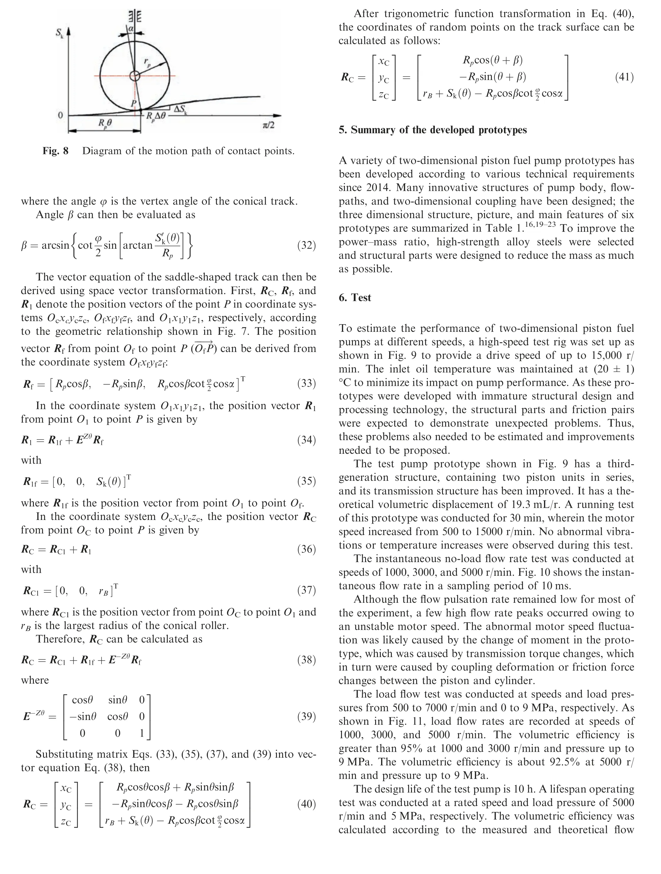

Table 1 Structure and feature of prototypes.


Table 1 (continued)

Fig. 9 Test rig for performance tests on the fuel pump.
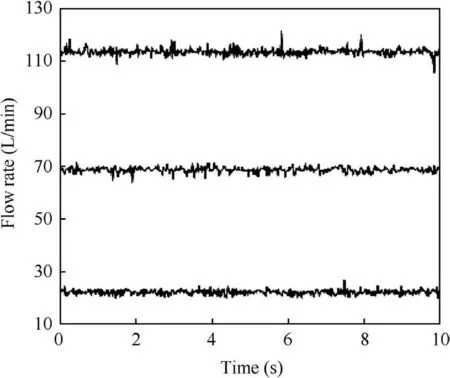
Fig. 10 Instantaneous no-load flow rate.
To examine the performance of the pump under extreme operating conditions, a trial was conducted under a maintained speed of 6800 r/min while regulating the pressure from 0 to 10 MPa. At a load pressure of 9.5 MPa, the test pump makes abnormal noise and the motor stops immediately, terminating the test early. Photographs of the damaged parts are shown in Fig. 13.
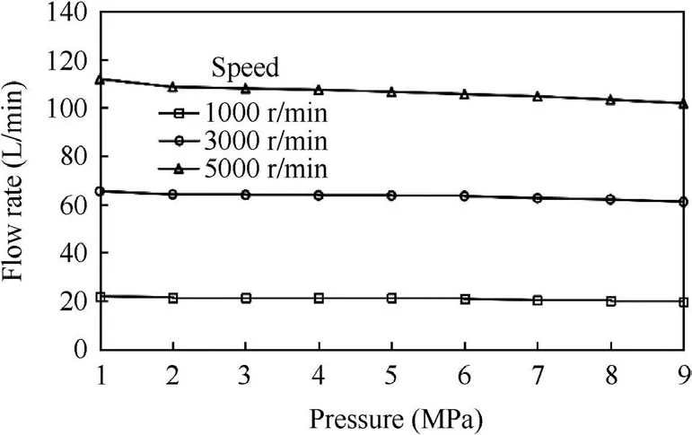
Fig. 11 Load flow rate at pressure from 1 to 9 MPa.

Fig. 12 Volumetric efficiency of the fuel pump in total life test.
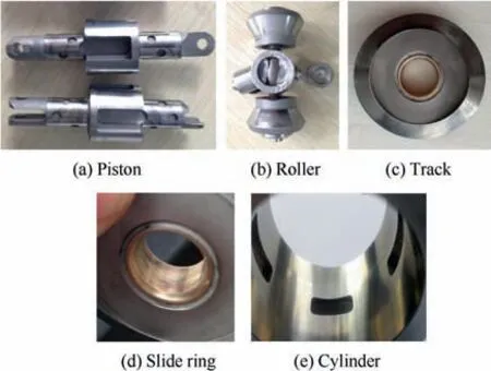
Fig. 13 Pictures of damaged parts.
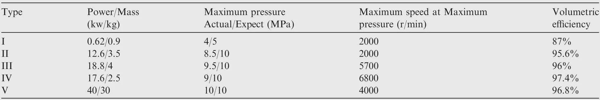
Table 2 Main technical data of prototypes.
As shown in Fig. 13(a) and (b), the connecting parts were broken. Obvious abrasions were on the surface of the track and slide ring, as shown in Fig. 13(c) and (d),respectively. Additionally, the inner surface of the cylinder was blackened, as shown in Fig. 13(e). Thus, preliminary conclusions were drawn: (i) the design of the connecting structures must be improved, as the connecting structures were damaged before reaching the maximal pressure; (ii)the abrasions on the contact surfaces indicate serious wear;and (iii) the local temperature at the inner surface of the cylinder is very high.
Five prototypes, whose technical data are summarized in Table 2, were tested following this experimental procedure.For accurate comparisons at varying operating conditions,the volumetric efficiencies were calculated using the data acquired at a load pressure and speed of 4 MPa and 2000 r/min, respectively.
7. Conclusions
In this work, common design methods and innovative structures of two-dimensional piston fuel pumps were studied.The testing of a new prototype was illustrated and analyzed.The following conclusions were drawn:
(1) A two-dimensional motion conversion mechanism can be designed with track or cam support, and the inertial force of the piston group can be balanced using the mechanism with reverse motion.
(2) The use of equal acceleration and deceleration motion laws is suitable for two-dimensional piston pumps as their wave pattern and the maximum dimensionless acceleration.
(3) The pairs of conical track and cone rollers are more suitable to two-dimensional piston pumps than the pairs of the parallel track and cambered surface roller as they considerably decrease contact stress.The relative sliding ratio of the pairs of conical tracks and cone rollers can be calculated.
(4) The track surface can be perfectly machined according to the derived vector equation.
(5) The volumetric efficiency of the studied two-dimensional piston fuel pumps exceeded 91% and were therefore deemed suitable to replace a gear pump or traditional axial piston pump as the main fuel pump.
(6) This design method can be extended to hydraulic pumps, motors, and air compressors using a twodimensional piston mechanism.
Acknowledgments
This study was co-supported by the National Natural Science Foundation of China (No. 51775500 and 51675482) and the Open Found of the State Key Laboratory of Fluid Power and Mechatronic Systems of China (No. GZKF-201822).
杂志排行

CHINESE JOURNAL OF AERONAUTICS的其它文章
- Reliability and reliability sensitivity analysis of structure by combining adaptive linked importance sampling and Kriging reliability method
- Aeroelastic dynamic response of elastic aircraft with consideration of two-dimensional discrete gust excitation
- Thermal damage analysis of aircraft composite laminate suffered from lightning swept stroke and arc propagation
- An aerospace bracket designed by thermo-elastic topology optimization and manufactured by additive manufacturing
- Applications of structural efficiency assessment method on structural-mechanical characteristics integrated design in aero-engines
- An energy-based coupling degradation propagation model and its application to aviation actuationsystem