An aerospace bracket designed by thermo-elastic topology optimization and manufactured by additive manufacturing
2020-06-11GunghuiSHIChengqiGUANDonglingQUANDongtoWULeiTANGTongGAO
Gunghui SHI, Chengqi GUAN, Dongling QUAN, Dongto WU,Lei TANG, Tong GAO,c,*
a Beijing Aerospace Technology Institute, Beijing 100074, China
b State IJR Center of Aerospace Design and Additive Manufacturing, Northwestern Polytechnical University, Xi’an 710072, China
c Institute of Intelligence Material and Structure, Unmanned System Technologies, Northwestern Polytechnical University,Xi’an 710072, China
KEYWORDS Additive manufacturing;Aerospace bracket;Selective laser melting(SLM);Thermo-elastic;Topology optimization
Abstract Combination of topology optimization and additive manufacturing technologies provides an effective approach for the development of light-weight and high-performance structures.A heavy-loaded aerospace bracket is designed by topology optimization and manufactured by additive manufacturing technology in this work. Considering both mechanical forces and temperature loads, a formulation of thermo-elastic topology optimization is firstly proposed and the sensitivity analysis is derived in detail. Then the procedure of numerical optimization design is presented and the final design is additively manufactured using Selective Laser Melting (SLM). The mass of the aerospace bracket is reduced by over 18%, benefiting from topology and size optimization, and the three constraints are satisfied as well in the final design.This work indicates that the integration of thermo-elastic topology optimization and additive manufacturing technologies can be a rather powerful tool kit for the design of structures under thermal-mechanical loading.
1. Introduction
Additive manufacturing,which is a technique of layer-by-layer build-up of a product from a Computer Aided Design (CAD)model,1has seen unprecedented growth as a manufacturing tool in some corporations for reducing mass and shortening reaction cycle,2and thus has been successfully adopted in many engineering applications.3-6
Topology optimization, which is a technique to seek the best structural configuration, has been widely accepted and adopted as an innovative design method in both academic research7and applications in aircraft, aerospace and mechanical engineering.8
Practical engineering cases in the past few years have proved that appropriate combination of topology optimization and additive manufacturing technologies results in an effective approach for the design of high performance structures.9,10For example, European Aeronautic Defence and Space company (EADS) Innovation Works obtained the innovative design of the hinge bracket of Airbus A320 using topology optimization and additive manufacturing technologies. Compared to the original design, a significant mass reduction of 64% is achieved.
In the last decades, structural topology optimization has been adopted as one of the most effective approaches in the engineering design community, especially in the aeronautical engineering. However, few applications of topology optimization involved structures subjected to thermal stress load. The thermal stress load caused by thermal expansion belongs to the so-called design-dependent loads which bring more challenges into topology optimization and have long been an important research topic.11The thermal stress load depends on the solid material layout and changes during the topology optimization process. Researches on the thermo-elastic topology optimization are reviewed as follows.
The homogenization method is introduced into the thermoelastic topology optimization to minimize the mean compliance.12Later, the Evolutionary Structural Optimization(ESO) method is adopted where the element thickness is used as the design variables.13Using the pseudo-density method,the Rational Approximation of Material Properties (RAMP)model14is proved to be more effective than the Solid Isotropic Material with Penalization (SIMP) model15in thermo-elastic topology optimization.16Recently,the thermo-elastic problem is also solved in the framework of the level-set based topology optimization.17,18
Furthermore, in thermo-elastic topology optimization, the considered structural responses are extended from mean compliance to stress constraint.19It has been found that an optimization formulation to uniform energy density leads to similar configuration to the maximum von-Mises stress minimization.20Meanwhile, the elastic strain energy minimization and mean compliance minimization lead to different optimized configurations and the former favours particularly the stress reduction.21
Thermo-elastic topology optimization is also extended to the design of compliant mechanisms,22simultaneous optimization of the microstructure of homogeneous porous material and macrostructure topology23and dynamic compliance minimization in a temperature field.24Besides, multiple materials were taken into account by introducing the concept of Thermal Stress Coefficient (TSC).16
This work focuses on the application of thermo-elastic topology optimization. An aerospace bracket is designed by thermo-elastic topology optimization and manufactured by additive manufacturing technology. The rest of this paper is organized as follows. In Section 2, the considered aerospace bracket is presented in detail. In Section 3, the topology optimization method of thermo-elastic structures is introduced and the sensitivity analysis is carried out. In Section 4, the aerospace bracket is designed with numerical optimization technique. In Section 5,the additive manufacturing procedure and the experimental validation of the aerospace bracket is briefly introduced. In the last section, the conclusions are presented.
2. Aerospace bracket
The considered spacecraft has a symmetrical pair of brackets and one is illustrated in Fig. 1. Two brackets bear the same mechanical forces and thermal stress load caused by temperature field. The mechanical forces are applied at the point KP and include the thrust load along the course direction (Fx)and the equivalent inertia force which is decomposed into a transverse force (Fz) and a vertical force (Fy). A constant non-uniform temperature field (20-250°C), as shown in Fig. 1, is assumed in this work.
The boundary conditions of the bracket consist of three parts. Nodes on the position holes (green surfaces) are totally fixed. The bottom surface (blue surface) and the bolt holes(orange surfaces) are constrained along Y-axis.
The original design in Fig. 1 has been tested and all mechanical performances are satisfied, as shown in Fig. 2. In practical engineering,the safety of a part is generally evaluated by the safety factor:
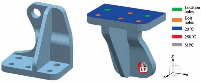
Fig. 1 Original design of the aerospace bracket.
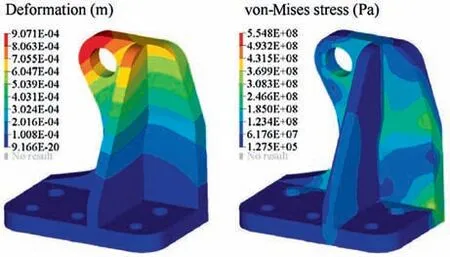
Fig. 2 Numerical analysis of original design.
where σpand σcare the tensile strength of the material and the maximum working stress of the part,respectively.Considering that the tensile strength of the material is 1321 MPa and the maximum von-Mises stress of the part is 554.8 MPa,the safety factor of this design is about 2.4. This value is relatively high from an engineering point of view and thus the structural mass can be further reduced. In order to reasonably remove excess materials and maintain the stiffness of the part,topology optimization is employed here to achieve an innovative design.
3. Thermo-elastic topology optimization
For a typical structural domain Ω, the equation that is solved for the thermo-elastic static linear analysis can be stated as

where K is the global stiffness matrix and u is the nodal displacement vector. Faand Fthare the nodal vectors of the applied force and of the thermal stress load, respectively.
At the finite element level, the element stiffness matrix and the nodal vector of thermal stress load of element e can be expressed as

Herein,V denotes a certain volume and Veis the volume of element e. The element strain-displacement matrix Beconsists of derivatives of element shape functions. ΔTedenotes the temperature rise of element e and φ=[1 1 1 0 0 0]Tfor 3D problems. Deis the elasticity matrix depending on Young’s modulus and Poisson’s ratio. The thermal stress coefficient βe, which can be treated as a material property, is defined as a function of the Young’s modulus (Ee), thermal expansion coefficient (αe) and Poisson’s ratio (μe)25.

3.1. Thermo-elastic topology optimization
In this work, a minimization of the global compliance subject to volume constraint is implemented to obtain the optimal configuration. Meanwhile, the horizontal displacement measured at the specified key point KP along the course directionis introduced as a constraint and its upper bound isThus, the formulation of this optimization problem is expressed as
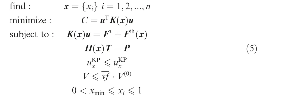
P, T and H are the global thermal load vector, nodal temperature vector and thermal conductivity matrix, respectively.Herein, the thermal stress load vector Fthdistinctly depends on the design variables while the applied mechanical force Faand thermal load P are assumed to be design-independent. n is the number of the designable finite elements and subscript i indicates the ith designable element. x denotes the set of design variables and a lower bound of the design variables,e.g., xmin=10-9, is introduced to avoid the singularity of the structural stiffness matrix and thermal conductivity matrix in finite element analysis.
The volume of the structure V and the whole design space V(0)are calculated with
where Videnotes the volume of the ith element.is the upper bound of the volume fraction.
3.2. Sensitivity analysis
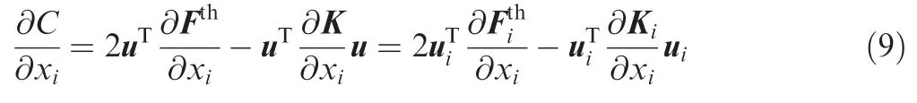
The sensitivity of the structural compliance then corresponds to

According to the thermo-elastic equilibrium equation, we have

The substitution of Eq. (7) into Eq. (6) yields
The displacement of the specified key pointcan be defined as

in which ΛKPis a vector.The sensitivity of uKPx can be derived as
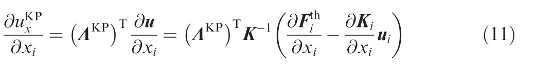
Suppose

The adjoint vector λKPcan then be obtained by

Thus,by means of the adjoint method,the sensitivity of the displacement of the specified key point can be obtained by only one additional finite element analysis.
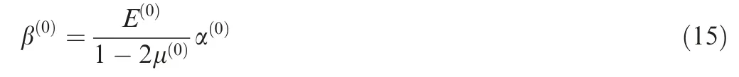
Evidently,∂Ki/∂xiand ∂Fthi /∂xican be easily derived at the element level according to the material interpolation model.In a thermo-elastic optimization problem, both the elasticity matrix and TSC should be parameterized to compute the element stiffness matrix and thermal stress load vector, respectively. Meanwhile, the thermal conductivity coefficient κishould be also parameterized if a heat conduction analysis is required for temperature field calculation. RAMP scheme,whose superior performance has been proved under designdependent thermos-elastic problem,16is adopted and the parameterized material properties are expressed as follows:

with internal parameters qD,qβand qκ.Herein,the superscript(0)indicates the properties of the available solid material.TSC of the solid material is calculated by
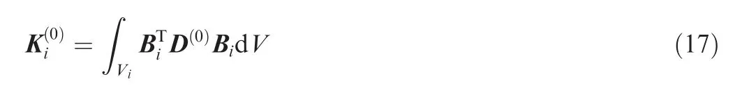
Thus, ∂Ki/∂xican be written as
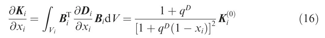
with
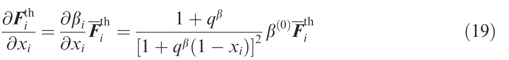
Similarly, the partial derivative of the thermal stress load can be stated as
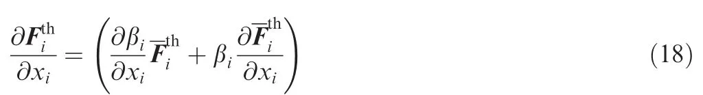
In this work,a constant temperature rise(∂ΔTi/∂xij=0)is assumed in each optimization iteration and the temperature field is updated after the steady-state heat conduction analysis using the interpolated thermal conductivity coefficient. This treatment could improve the calculation efficiency without causing an obvious deterioration of the design accuracy. The partial derivative of the thermal stress load is then simplified as
4. Optimization design of the aerospace bracket
In this section, an aerospace bracket is successively designed using topology and size optimization.
4.1. Topology optimization
The design space for topology optimization is firstly defined by extending the original geometric model of the aerospace bracket and several structural features of the holes are supposed to be non-designable, as shown in Fig. 3.

Fig. 4 Flow chart for the topology optimization.
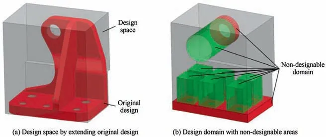
Fig. 3 Geometric model for topology optimization.
The objective function of the topology optimization problem is defined as the minimization of the global compliance.The displacement of the specified key point (KP in Fig. 1)along the course direction should be less than 0.5 mm. This threshold value was proposed referring to that of the original design.The other constraint is the volume fraction of the solid material whose upper bound is set to be 0.15, while the stress constraint is not included in the topology optimization. The Convex Linearization(ConLin)method is employed to update design variables and a detailed optimization procedure is given in Fig. 4. The optimized structural configuration of the aerospace bracket is illustrated in Fig. 5.
4.2. Reconstruction
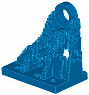
Fig. 5 Optimized structural configuration of the aerospace bracket.
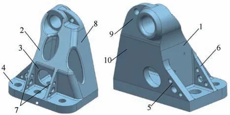
Fig. 6 Reconstructed aerospace bracket.
Based on the optimized structural configuration,the aerospace bracket is re-modelled.As illustrated in Fig.6,the reconstruction of the optimized bracket structure follows the principles below. Firstly, the assembly process should be considered.For example,the operation space for all bolts should be enough.Secondly, the reconstruction result should be approximate to topology optimization result as far as possible. Thirdly, the bracket can be manufactured by Selective Laser Melting(SLM)with a hollow main body and several shaped holes.
4.3. Size optimization
Based on the reconstructed model, size optimization is carried out to achieve a final design of the aerospace bracket. Thicknesses of 10 zones (ti), as shown in Fig. 6, are considered as the design variables in the size optimization. The initial values and the lower and upper bounds of all design variables are listed in Table 1. It should be mentioned that the increment of all design variables is 0.5 mm.
To reduce the structural weight as possible, the structural mass m is chosen as the objective function in the size optimization procedure. The displacement of KP along the course direction should be less than that of the original design. As for the performance constraints, the horizontal displacement at KP is restricted. Besides, a maximum von-Mises stress level of 650 MPaand the lower bound of the buckling factor 60are imposed. In our work,only linear buckling is considered and the critical buckling load is calculated using the Lanczos method.
Thus, the formulation of the size optimization problem is expressed as

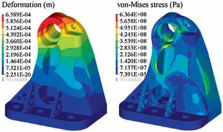
Fig. 7 Numerical analysis of final design.

Table 1 Design variables in size optimization.

Table 2 Comparison of original and optimized designs.
The optimized values of all design variables are shown in Table 1 and the deformation and von-Mises stress distributions of the final design are plotted in Fig. 7. A comparison of the original and optimized designs is illustrated in Table 2.Benefiting from topology and size optimization, the mass of the aerospace bracket is reduced by 18.3%.
5. Manufacture and test of the aerospace bracket
In this section, the mechanical performance of the optimized aerospace bracket,which is produced by additive manufacturing, is tested.
5.1. Additive manufacturing
By using the BLT-S300 platform, an advanced SLM platform from Xi’an Bright Laser Technologies Co., Ltd (BLT), the final design of the aircraft bracket was additively manufactured using the titanium-alloy TC4 powder. The precursor powder’s particle size is rather fine,ranging from 15 to 53 μm.
Fig.8 illustrates the model used in additive manufacturing.In this work,no manufacturing constraints were considered in the optimization process hence supporting structures are necessary for printing the optimized design. In order to reduce the amount of supporting structures and ensure their removal,the model is rotated about 20°. To guarantee a good performance of the printed parts, the experimentalists from both BLT and Beijing Aerospace Technology Institute have carefully chosen the processing parameters, e.g. the laser power of 360 W, the layer thickness of 60 μm and hatching space of 120 μm. And the scanning trajectory is rotated for 67° after printing each layer to reduce residual stress during the additive manufacturing process. The printed sample part of the aerospace bracket is presented in Fig. 9.

Fig. 8 Model of aerospace bracket for SLM.
5.2. Experimental validation

Fig.9 Sample part of aerospace bracket manufactured by SLM.

Fig. 10 Tri-axial tensile test for bracket.
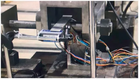
Fig. 11 Experimental settings for the tri-axial tensile test.

Fig. 12 Displacement of KP point along the course direction in the tri-axial tensile test.
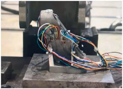
Fig. 13 Unloaded bracket.
The material properties of the printed sample part was tested firstly.Three standard dog-bone specimens were printed simultaneously with the bracket. According to the tensile tests on these standard specimens, we derived an averaged Young’s modulus of 110 GPa and a Poisson’s ratio of 0.34.Meanwhile,the elongation, the tensile strength and the 0.2% yield strength are observed to be 6.5%-10%, 1210-1321 MPa and 1085-1190 MPa, respectively. By comparing with the properties of the raw material provided by the supplier,the properties of the printed specimens are sufficient and the processing parameters are confirmed.
Furthermore, a tri-axial tensile test was carried out to validate the mechanical performance of the printed bracket under the extreme loading condition. The experimental scheme is illustrated in Fig. 10 while the loading and measuring system is shown in Fig. 11. The forces along three directions are loaded step by step with an increment of 5% of the extreme forces. In each step, the incremental forces are gradually loaded in 5 s and then maintained for another 5 s.
The displacement at KP along the course direction was recorded during loading process, as shown in Fig. 12, and a value of 0.61 mm is observed under the maximum load. The unloaded bracket is shown in Fig. 13 and no unrecoverable deformation occurred. Though the maximum displacement of concern in the test violated the given upper bound in the optimization process, it is still regarded as acceptable taking into account the relatively small absolute value and the experimental errors induced by assembly. Overall, we consider that the final optimized design is reliable for actual use.
6. Conclusions and perspectives
A heavy-loaded aerospace bracket is optimized using both topology and size optimization for mass reduction and then manufactured by additive manufacturing technology.To meet the requirement of the aerospace bracket design,a formulation of thermo-elastic topology optimization is proposed and the sensitivity analysis is detailed.By adopting the structural optimization method,more than 18%of the structural mass of the aerospace bracket is reduced and all mechanical performances are satisfied.Benefiting from SLM technique,the complex final design including the hollow main body and several shaped holes could be rapidly manufactured, while the hollow main body brings severe difficulty to traditional manufacturing technologies.The whole design process is presented in Fig.14.This work indicates that the combination of topology optimization and additive manufacturing technology provides a powerful tool kit to the engineering designers and they are an amazingly good fit.

Fig. 14 Aerospace bracket designed by topology optimization and manufactured by additive manufacturing.
In our future works, we would like to involve manufacturing constraints in the topology optimization. As known to all,considering manufacturing constraints in the design phase will enhance the manufacturability of the final design. Some researchers take into account the overhang constraint in topology optimization and try to achieve so-called self-supporting designs,26-29while others are trying to design and reduce the supporting structures.30All these works about the manufacturing constraints are of great importance for further combination of topology optimization and additive manufacturing.However, we think more efforts are still necessary to eventually adopt these methods to complex and large-scale engineering cases.
Acknowledgements
This work is supported by the National Key Research and Development Program of China (Nos. 2017YFB1102800,2016YFB0201600), the National Natural Science Foundation of China (Nos. 11672239, 51735005).
杂志排行

CHINESE JOURNAL OF AERONAUTICS的其它文章
- Reliability and reliability sensitivity analysis of structure by combining adaptive linked importance sampling and Kriging reliability method
- Aeroelastic dynamic response of elastic aircraft with consideration of two-dimensional discrete gust excitation
- Thermal damage analysis of aircraft composite laminate suffered from lightning swept stroke and arc propagation
- Applications of structural efficiency assessment method on structural-mechanical characteristics integrated design in aero-engines
- An energy-based coupling degradation propagation model and its application to aviation actuationsystem
- Model-driven degradation modeling approaches:Investigation and review