A multi-constraints based pose coordination model for large volume components assembly
2020-06-11DianWUFuzhouDU
Dian WU, Fuzhou DU
School of Mechanical Engineering and Automation, Beihang University, Beijing 100083, China
KEYWORDS Large volume components;Measurement assisted assembly;Multi-constraints;Pose estimation;Pose evaluation
Abstract In the assembly process of large volume product, engineering constraints limit the relative pose of components and serve as a standard for judging assembly quality.However,in the traditional process of target pose estimation, a general method is needed for establishing the correlation between engineering constraints and product pose, and it is difficult to evaluate pose by constraints comprehensively. Therefore, the process of target pose estimation and evaluation is separated.In this paper,a pose coordination model based on multi-constraints is proposed,which includes pre-processing,pose estimation,pose adjustment and evaluation.Firstly,engineering constraints are decoupled into 4 types of Minimum Geometrical Reference Constraints (MGRC), and the inequalities for solving target pose are formulated. Then the Constraint Coordination Index(CCI) is defined as the optimization objective to solve the target pose. Finally, with CCI as the numerical index, the target pose is evaluated to illustrate the quality of assembly. Taking the simulation experiment of wing-fuselage jointing as an example,the external and internal parameters of model are analyzed, and the pose estimation based on multi-constraints reduces the CCI by 12%,compared with the point-set-registration method.
1. Introduction
The products in aviation, aerospace and shipbuilding industries are huge in size and complex in manufacturing process.The quality of product largely depends on the final assembly of large volume components which is the key of production.1-3However, due to the dimensions of objects and the accumulated errors of sub-assembly, it is difficult to make the product geometrically consistent with the design model.In addition to manufacturing errors, there are measurement errors, so the measured coordinates of product feature points are always different from their design values. The general assembly process of large volume components includes 4 stages: measurement, pose estimation, pose adjustment and evaluation.In the measurement stage,the original data are collected by measuring equipment such as laser tracker,4,5total station6,7and indoor Global Positioning System (iGPS).8,9In the pose estimation stage, Singular Value Decomposition(SVD),10least squares,11or intelligent algorithm12is used to fit the pose with the measured and design values of product feature points. In the pose adjustment stage, taking the fitted pose as input, the component is adjusted to the target pose by pose adjusting mechanism such as Stewart platform,13parallel positioner14and robot.15In the pose evaluation stage, all engineering constraints, such as the angle of dihedral and sweepback in the wing-fuselage jointing,16are checked for any over-range, and then the corresponding pose evaluation conclusion is given. In addition to the simple pose evaluation method mentioned above,there are other more comprehensive methods, such as the evaluation method based on uncertainty of pose measurement.17,18
However, some problems in the above process need to be solved urgently. The optimization objective of the pose estimation algorithm based on the point-set-registration method is to minimize the total distance of the feature points between the object and the model. On the contrary, the standard of pose evaluation is the satisfaction of engineering constraints, which means that the calculated target pose is the optimal one provided by the algorithm, but not the optimal one desired by the engineering. This contradiction also divides the process of target pose estimation and evaluation. As a result, pose evaluation can only be used as a validation process after pose estimation,but cannot drive pose estimation or predict the quality of the target pose. Besides, if there is any over-range engineering constraint, it is necessary to fine-tune the pose. Considering the component as a rigid object, adjusting the pose for any constraint will inevitably affect the satisfaction of other constraints.It may take repeated attempts to find the appropriate target pose which can satisfy all the tolerance requirements,thus making the whole fine-tuning process lengthy.
The main reason of these problems is that the engineering constraints are not taken into account in pose estimation,and there is no comprehensive numerical index for pose evaluation. To solve these problems, researchers have proposed some solutions. Li et al.19combine several typical engineering constraints including collinear, coplanar, and symmetry with the point registration model in different weights,and construct the optimization objective for pose estimation. Zheng et al.20take synthetic error of points for each engineering constraint as the optimization objective and use particle swarm optimization to estimate the pose.Wang et al.21construct a comprehensive evaluation index by manufacturing feature points and coordinated feature points, and use penalty function method to estimate pose within the range of constraint tolerance.
In this paper,a new pose coordination model for large volume components based on multi-constraints is proposed.Firstly, all engineering constraints are decoupled into 4 kind of primitive constraints, and the corresponding inequalities are formulated. Secondly,considering the satisfaction of these constraints relative to their tolerance requirements, the CCI is proposed to evaluate target pose.Naturally, CCI is also set as the optimization objective in the pose estimation algorithm.In addition, an example of wing-fuselage jointing is constructed.Comparing with the point-set-registration method, the pose coordination model is verified, and the crucial internal and external parameters of the model are analyzed by simulation.
2. Pose estimation based on the point-set-registration method

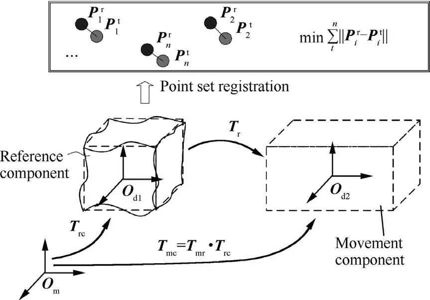
Fig. 1 Pose estimation based on the point-set-registration method.

To ensure the accuracy of pose in this method, data errors are spread to every feature point based on the threedimensional model. But engineering constraints are neglected in pose estimation, not to mention considering engineering constraints differentially. Besides, because the solved pose(including the position and orientation) is six-dimensional, it is difficult to directly evaluate the quality of assembly, and a simpler and more practical numerical index is needed in pose evaluation.
3. Pose coordination model based on multi-constraints
3.1. Minimum geometrical reference constraints
A group of relation between the related geometrical features from different assembly components constitute engineering constraints, in which geometrical elements can be decoupled to the Minimum Geometrical Reference Elements (MGRE),namely point, line and plane.22The engineering constraints between assembly components can be expressed equivalently by a set of MGRE coordination relations.Each of the relation contains two MGRE, but in some special cases it contains three or more MGRE, in which case the constraint needs to be split to the simplest mode containing two MGRE. For example, for features A and B on symmetry reference C, the symmetry constraint can be transformed into two constraints,A-C and B-C.
The cross-matrix of MGRE is constructed as shown in Fig. 2, where d denotes the existence of distance constraint, θ denotes the existence of angle constraint, and d||denotes the existence of distance constraint only when the involved elements are parallel. Three properties can simplify the crossmatrix of MGRE:
(1) The analysis method of each constraint is only related to the type of geometrical elements,but not to the reference element. Therefore, the cross-matrix of MGRE is symmetrical, and only the lower triangular matrix needs to be concerned.
(2) When considering the distance constraint between a plane and a line or between a plane and another plane,the plane can degenerate into any line in the plane, in the condition that they are parallel. When considering the angle constraint between them, the normal line of the plane and angle sum of a triangle can be used for problem transformation.
(3) When considering the distance relationship between lines, one of the lines can degenerate to a point on the line, which is also on the vertical line of the two lines.
Finally,the cross-matrix of MGRE is simplified into 4 basic cooperation relationships: point-to-point distance dpp, pointto-line distance dpl, point-to-plane distance dpaand line-toline angle θll. They are defined as the Minimum Geometrical Reference Constraints (MGRC) in this paper.
In this way, all the engineering constraints between assembly components can be decoupled and simplified into a set of MGRC to facilitate later pose estimation.
Let the algebraic expression of MGRE (point, line, plane)on the reference component be as Eqs. (1)-(3).

Similarly,let them on the movement component be as Eqs.(4)-(6).

Using the undetermined relative pose, including position tmrand orientation Rmr, the algebraic expression of MGRC(point-to-point distance, point-to-line distance, point-toplane distance and line-to-line angle) can be derived as Eqs.(7)-(10).In the equations,converting Pmto the design coordinate system of the reference component, there are Pmr=Rmr·Pm+tmr. The normal vector of plane Axx+Bxy+Cxz+Dx= 0 is nx= [Ax,Bx,Cx], and Nxrepresents the direction vector of a spatial line. The tolerance range of certain constraint is between εLXand εHX. The symbol with star represents the theoretical value of the corresponding MGRC.

Fig. 2 Cross-matrix of MGRE.

3.2. Constraint coordination index
In pose estimation algorithm, the optimization objective and the constraint inequalities are formulated according to the deviation between the calculated value and the design value of each MGRC. The construction principle of the optimization objective is to minimize and equilibrate all MGRC deviations.

The average of xiis shown in Eq.(12),and it represents the total value of MGRC deviations.

Twice the standard deviation of xiis shown in Eq.(13),and it represents the equilibrium of MGRC deviations.

The multi-constraints optimization problem can be established as Eq. (14), which can be solved by the optimization algorithm23or the heuristic intelligent algorithm.24,25λμ + 1-λ( )σ is the algebraic expression of CCI and λ ∈ (0 ,1) is the balance factor of CCI. dior θirepresents the actual result of MGRC,orrepresents the corresponding theoretical value andrepresent the lower and upper bounds of MGRC tolerances respectively. When estimating the target pose, λ regulates the importance of the total value and the equilibrium of MGRC deviations, and the smaller CCI is, the better.
When all MGRC deviations satisfy tolerance requirements,xibelongs to 0 to 1,and it can be proved that μ,σ ∈ (0 ,1).As a result, there is λμ + (1 -λ)σ ∈ (0 ,1).

CCI is dominated by MGRC deviations through η, μ, σ and λ.In addition,because CCI is a numerical index,the pose can be evaluated numerically. For different poses of the same assembly system, they can be directly compared by CCI.
3.3. Process of pose coordination
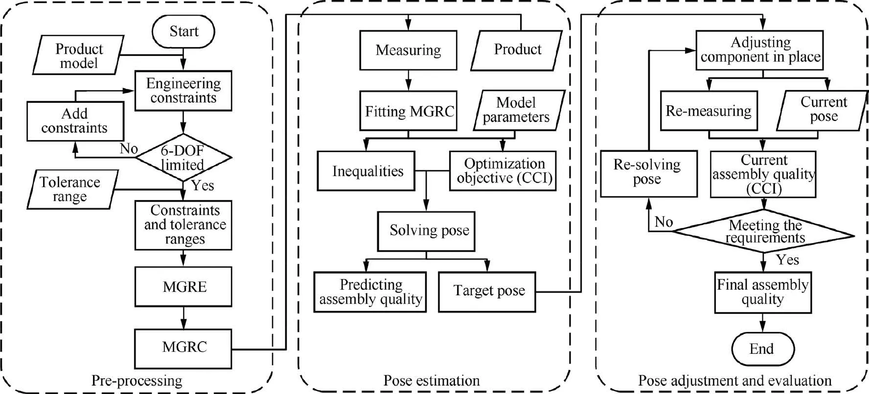
The pose coordination process of large volume components can be divided into 3 steps: 1. pre-processing; 2. pose estimation; 3. pose adjustment and evaluation, as shown in Fig. 3.
Step 1: Firstly, according to the design model of product,the original engineering constraints are selected. Secondly, it needs to be confirmed whether these engineering constraints can limit the relative 6-degrees-of-freedom of components.26If not,new engineering constraints need to be added.The purpose is to ensure that the solution is unique in the process of pose estimation. Then, the tolerance range should be deduced according to the requirements of constraint tolerance in the assembly task.Finally, the assembly features involved in engineering constraints are transformed into MRGE, then the MGRC and their tolerance ranges are constructed.
Step 2:Firstly,based on the constructed MGRC,the corresponding feature points on the product are measured, and the corresponding algebraic expressions of MGRC are formulated by direct measurement data or indirect fitting data. Then, the parameters of the pose coordination model are set according to the actual engineering requirements, and the optimization objective (CCI) and the inequalities are determined to solve target pose. Finally, the target pose and its CCI are solved. Since the target pose are not achieved at this time, the CCI acts as a predicted value in the current condition.
Step 3:Firstly,the movement component is adjusted to the estimated target pose by the pose adjusting mechanism. Then,the involved feature points of components are measured again,then the current CCI can be calculated.If the CCI satisfies the preset value at this time, the assembly process is terminated with the current pose, and the current CCI is the final index of assembly quality. But if not, it is necessary to substitute the measured values into the pose estimation algorithm again,calculate the new target pose, then iterate all the process of step 3.
4. Simulation experiment and analysis
4.1. Construction of the simulation experiment
Taking wing-fuselage jointing as the research object,the simulation experiment is constructed,as shown in Fig.4.Being the reference component of assembly, there are feature points P1, P2, P3on the fuselage as describe in Table 1. Being the movement component of assembly, there are feature points P4, P5, P6, P7on the wing as shown in Table 2.
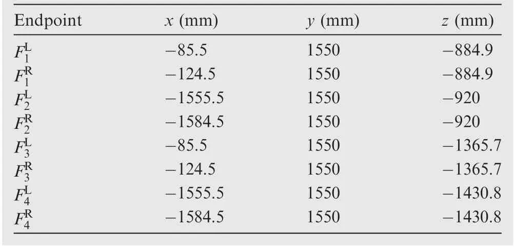
The wing and fuselage are jointed by the attachment lugs,and there are 4 lugs on the fuselage and 6 on the wing. The specific correspondence between them is shown in Fig.5.Taking 1-1 lug pair as an example, the hole axis endpoints of the two lugs areand, respectively. max(r1,r2) is the maximum radial runout between the two axes of hole,which corresponds to the radial runout tolerance. c1is the clearance between the two lugs, which corresponds to the transverse clearance tolerance. When the final assembly is completed,the values of all hole axis endpoints of the fuselage and wing model are shown in Tables 3 and 4.
In Fig.6,the special angles of the wing are expressed by the 4 feature points on the wing, including:
(1) Sweepback angle: backward angle of wing trailing edge from the y-z plane.
(2) Dihedral angle: the upward angle of wing front edge from the x-y plane.
(3) Setting angle: the upward angle of chord line of wing root from the x-y plane.
When the model at the theoretical assembly state, the design values and the corresponding tolerance ranges of the above five constraints are shown in Table 5.
4.2. Comparison of two methods
Regarding the wing and fuselage as rigid objects, let the measuring coordinate system be coincided with the model design coordinate system, and the initial relative pose between the wing and fuselage be T1= [x,y,z,a,b,c].Then,the theoretical target pose of the wing should be T0= [0 mm, 0 mm, 0 mm, 0°, 0°, 0°].Considering the manufacturing error and measurement error synthetically, The Gauss noise N(0,)is added to each dimension of the feature point coordinate to simulate the synthetic error.
To compare the method of point-set-registration and that proposed in this paper, the target pose TWof the wing in the measurement coordinate system is estimated by different methods respectively.

Fig. 3 Process of pose coordination.

Fig. 4 Model sketch of wing-fuselage jointing.

Table 1 Coordinates of feature points on fuselage.

Table 2 Coordinates of feature points on wing.
For the point-set-registration based pose estimation method, the pose TFof the fuselage in the measurement coordinate system is fit by the 11 feature points from Tables 1 and 3. When the theoretical target pose of the wing relative to the fuselage is T0, it can be deduced that the target pose of the wing relative to the measuring coordinate system is TW=T0TF=TF.
For the multi-constraints based pose estimation method,engineering constraints need to be decoupled firstly. For example, the radial runout is transformed into point-to-line distance, and the lateral clearance is transformed into pointto-plane distance, as shown in Fig. 5. Three special angles of wing are transformed into line-to-line angle, as shown in Fig.6.Their corresponding design values and tolerance ranges are defined by Table 5.Then,a constrained optimization problem is constructed to estimate the target pose.
There are 6 pairs of lugs,each of which contains 3 MGRC,and 3 wing angles. A total of 21 MGRC are included in the pose coordination model,based on the data generated in chapter 4.1. The parameters of the model are set as σN=0.02 mm,ηi=1/21, λ=0.5. In the case of initial pose T1= [350 mm, 550 mm, 200 mm, 3°, 5°, 2°], the target pose estimated by the two methods are both close to the theoretical pose T0, as shown in Table 6.

Fig. 5 Specific correspondence between lugs.

Table 3 Endpoint coordinates of lugs on fuselage.

Table 4 Endpoint coordinates of lugs on wing.
4.3. Discussion on model parameters
The important parameters involved in the pose coordination model are divided into external and internal parameters. The external parameters include the noise of data σN, the number of MGRC n, and the internal parameters include the weight factor ηiof MGRC and the balance factor λ of CCI.

Fig. 6 Three special angles of wing.

Table 5 Design values and corresponding tolerance ranges.
4.3.1. Noise of data
With other parameters invariant,several σNare selected in the range of 0.005 - 0.035 mm. For each σN, 100 different sets of noisy data are generated, and the average CCI corresponding to each σNby two methods is calculated as shown in Fig. 7.
Fig. 7 illustrates that as the noise increases, the CCI increases and the satisfaction of all MGRC becomes worse.Because the theoretical pose is solved without considering data noise and MGRC, its CCI is the largest. Although the point-set-registration method considers data noise, it does not consider MGRC, so its CCI is in the middle. The multiconstraints method takes both factors into account, so its CCI is the smallest.

Table 6 Comparison of estimated pose.
When σN=0.02 mm, the average CCI of the point-setregistration method is 0.0292, and that of multi-constraints method is 0.0255. There is a 12% reduction.
4.3.2. Number of MGRC
By adjusting the number of lug pairs, the influence of MGRC number in the pose coordination model is analyzed.In chapter 4.1, six pairs of lugs are constructed, from whichcombination ways can be obtained by choosing n = 3,4,5,6 pairs of lugs. When the number of lug pairs is n, the corresponding average CCI is the average of all possible combinations’CCI. Similarly, 100 sets of noise data are used to solve the average CCI for each n. The final results calculated by the two methods are shown in Fig. 8.
Fig. 8 illustrates that the greater the number of MGRC is,the greater the CCI becomes. Because when more MGRC are considered, it is more difficult to coordinate and to satisfy these MGRC at the same time.
The method based on multi-constraints is more sensitive to the number of MGRC than the method based on the point-setregistration method. For the former, fewer MGRC will make the space of solution larger and it is easier to find a smaller CCI,so the slope will be larger. For the latter, the pose fitting is to overcome the influence of data noise, and the noise level of each lug pair is the same.Therefore,when adding or removing some lug pairs,the variation of pose is small,so the corresponding CCI is linear with the number of lug pairs.
4.3.3. Weight factor of MGRC
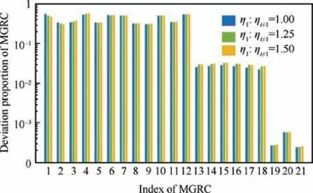
Fig.9 shows that adjusting the weight ηiof MGRC can change their priority. The larger the weight proportion is, the greater the influence becomes,and the better the MGRC satisfies when reaching the target pose.

Fig. 7 Impact of noise on CCI.

Fig. 8 Impact of MGRC number on CCI.

Fig. 9 Impact of weight factor on MGRC deviations.
Among the 21 MGRC, the proportion of 1-1 MGRC is adjusted to analyze the influence of weight. When ηi=1/ηi≠1,i ∈[1,21] equal to 1, 1.25, 1.5 respectively, the importance of 1-1 MGRC increases and the relative deviation decreases gradually. But this improvement sacrifices the satisfaction of the other MGRC.
4.3.4. Balance factor of CCI
When the final assembly is completed, the error proportion of each MGRC should be as small as possible. However, all MGRC are competing with each other and cannot reach their minimum respectively at the same time. The average μ in CCI is used to control the total trend of all MGRC.When the total value of MGRC is optimal, another problem will arise. Some MGRC satisfy well while others do not.For this problem,the standard deviation σ in CCI is introduced to control the equilibrium trend of all MGRC, so that the deviation level of all MGRC is close to each other. Therefore, the role of the balance factor λ is to adjust the influence of the two effects in the model.

Fig. 10 Impact of balance factor on MGRC deviations.
Based on the data in chapter 4.1,only changing the value of λ from 0 to 1,Fig.10 illustrates the effect of λ on the distribution of deviation proportions for all 21 MGRC. In the boxplot, the two horizontal lines at top and bottom represent the maximum and minimum values, the top and bottom of the rectangle represent the quartiles, the horizontal red line represents the median, and the blue cross symbol represents the average.
It can be found that with the increase of λ, the deviation proportion distribution (the upper and lower quartiles) of all 21 MGRC is more scattered but the average (blue cross symbol) is smaller. It indicates that when concerning on the total value of MGRC deviations primarily, a larger λ is needed.when concerning on the equilibrium of MGRC deviations primarily, a smaller λ is needed.
5. Conclusions
(1) Based on the MGRE, the concept of MGRC is proposed.For the different types of engineering constraints,they can be decoupled into MGRC,and then the general method is applied for pose estimation and evaluation.
(2) Based on the MGRC, a constraint coordination index CCI is proposed. The index includes the weight factor and balance factor of MGRC, and can be customized for specific assembly situation. Besides, CCI can complete the pose evaluation while estimating the pose. It can not only predict the assembly quality, but also be the final numerical evaluation index.
(3) According to MGRC and CCI, a pose coordination model for assembly of large volume components are proposed.By the workflow of the model,the simulation experiment of wing-body jointing is constructed. The internal and external parameters of the model are analyzed by comparing with the point-set-registration method, which provides a reference for custom use.
Acknowledgement
This work was supported by the Special Research on Civil Aircraft of China (No. MJZ-2017-J-96); and the Equipment Pre-research Project of China (No. 41423010401).
杂志排行
CHINESE JOURNAL OF AERONAUTICS的其它文章
- Reliability and reliability sensitivity analysis of structure by combining adaptive linked importance sampling and Kriging reliability method
- Aeroelastic dynamic response of elastic aircraft with consideration of two-dimensional discrete gust excitation
- Thermal damage analysis of aircraft composite laminate suffered from lightning swept stroke and arc propagation
- An aerospace bracket designed by thermo-elastic topology optimization and manufactured by additive manufacturing
- Applications of structural efficiency assessment method on structural-mechanical characteristics integrated design in aero-engines
- An energy-based coupling degradation propagation model and its application to aviation actuationsystem
