Machining fixture for adaptive CNC machining process of near-net-shaped jet engine blade
2020-06-11DongboWUHuiWANGJinsongPENGKiyoZHANGJieYUXuesongZHENGYunhiCHEN
Dongbo WU, Hui WANG,*, Jinsong PENG, Kiyo ZHANG,b, Jie YU,Xuesong ZHENG, Yunhi CHEN
a State Key Laboratory of Tribology, Beijing Key Lab of Precision/Ultra-Precision Manufacturing Equipment and Control, Department of Mechanical Engineering, Tsinghua University, Beijing 100084, China
b Yantai University, Yantai 264005, China
c AECC Xi’an Aero-engine LTD, Xi’an 710021, China
d BEIJING POLYTECHNIC, Beijing 100176, China
KEYWORDS Adaptive CNC machining process;Clamping force;Clamping sequence;Fixture displacement response;Machining fixture;Near-net-shaped blade
Abstract Low stiffness and positioning problems are difficulties and challenges in the precise machining of near-net-shaped blades. This paper aims to achieve high accuracy in manufacturing by fixture- and deformation-control in the adaptive CNC machining process. Adaptive CNC machining technology is first analyzed,and new fixture-evaluation criteria and methods to evaluate the adaptive CNC machining process fixture design are built. Second, a machining fixture is designed and manufactured after analyzing its positioning scheme, clamping scheme, materials(PEEK-GF30), and structure characteristics. Finally, the designed fixture is analyzed by FEA and experimentally verified by a cutting experiment. The results show that the deformation of the blade is an overall rigid-body displacement, the main deformation of the blade-fixture system occurs on the four clamping heads, and this fixture can effectively protect the blade from local deformation. The proposed clamping-sequence method reliably and effectively controls the local maximum deformation of the blade.The system stiffness is increased by 20 Hz,with each clamping force increased by 200 N.Both high-and low-frequency displacement in roughing milling or finishing milling are acceptable relative to the accuracy demand of blade machining. This fixture and an adaptive CNC machining process can achieve high accuracy in blade manufacturing.
1. Introduction
As one of the key components of an airplane engine,the blade plays a vital role in its overall performance. The design and manufacture of blades is a challenging scientific problem due to their large numbers, complex shapes, high-performance demands, difficulty in mechanical processing, and propensity to failure.1In addition,blades operate for long periods of time under the harsh conditions of high temperatures, pressures,and speeds.These conditions place high requirements on blade materials and the processes of machining, heat treatment, and surface spraying.2As the last step in the blade-forming process, machining plays a vital role in the mechanical properties of the blade3and is complicated due to the material and structural characteristics of the blade. Titanium alloy and hightemperature alloy are the main materials for airplane engine blades due to their high performance and low weight, and these materials are typically difficult to machine due to their high cutting temperature and severe process hardening. The blade body portion is a typical thin-walled free-form surface with a tiny radius of the leading and trailing edges and a complex and variable radius of curvature at different points.4Wind tunnel experiments were used to design a blade with fluid properties.
Precision forging, as a typical near-net-shaped process,5is an important development in the manufacture of titanium alloy parts for airplane engines and is especially suitable for blades. Precision-forged blades have better reliability, service life, and fatigue resistance at high temperatures, high pressures, and high-speed rotation, and the accuracy of the main parts meets the requirements of the blade. However, the contour accuracy of a precision-forged blade tenon root and tip cannot be used directly in airplane engines and must be CNC-machined due to the poor forming accuracy of precision forging for small radii and geometrically complex parts. CNC machining is the guarantee of the final quality of the blade.Sculptured surfaces and thin-walled shapes will have a negative effect on the machining accuracy of the blade tenon root and tip, and the machining fixture and CNC process will have a dominant influence on the final machining quality.6Positioning is especially difficult in machining the blade tenon root because the positioning part is only the blade body surface,which has a contour error of 0.08 mm after precision forging,leading to inaccurate positioning. Clamping is also difficult because this blade is a typical thin-walled, free-surface part whose low stiffness cannot bear large cutting and clamping forces.7Therefore, the difficulty of positioning and low stiffness are the two major problems in CNC-machining a blade tenon root.
At present, the blade is poured by a low-melting-point alloy to form a square box, which is used as a positioning reference and clamping body to indirectly clamp the blade.The alloy is made from bismuth, cadmium, and lead, and its melting point is near 850°C.8This clamping solution solves the problems of positioning and low stiffness and is one of the most commonly used process methods. However,there are still many defects in the context of intelligent manufacturing. For instance, positioning accuracy is reduced due to positioning benchmark conversion9caused by a free-form-surface six-point positioning fixture before pouring and the large positioning error of pouring the square box caused by heat effects.10The residue of the alloy is not completely removed after processing by a nitric acid solution, and this affects the performance and quality of the blade surface and reduces its fatigue strength and impact strength.2This process is inefficient and expensive and cannot be automated to a high degree. The offline production method requires the blade to be removed from the production line and taken to a separate workshop for manual pouring.
The problem of low stiffness is solved by multi-point positioning and auxiliary support, which can increase the system stiffness and reduce the deformation of thin-walled parts by changing their force state. A fixture can directly clamp the blade, and an auxiliary support to enhance the stiffness of the blade-fixture system. However, an auxiliary support is not conducive to milling because it interferes with the cutter.After one side of the tenon root is milled, the blade must be turned over to mill the other side,which seriously impacts cutting efficiency and consistency. Our research team11improves the auxiliary support scheme based on machine tool-fixture linkage. The auxiliary support can avoid the cutter by automatically expanding and contracting the hydraulic auxiliary support block, and it can be automatically locked to avoid changing the blade position when subjected to a force of approximately 5 N. The hydraulic system control program can be integrated into the machine tool motion-control system.This scheme can avoid secondary clamping and improve efficiency and consistency. The equipment and process scheme have a certain application value and will be displayed at the 12th China International Machine Tool Show (CIMES2014).However,this research idea and process solution are improvements to the traditional scheme and only increase the system stiffness; they do not systematically solve the problem of difficult positioning and low stiffness. With the development of digital-detection technology and the promotion of detection precision and speed,12,13adaptive CNC machining technology14,15can be used in blade manufacturing. The accuracy of blade positioning will be greatly improved because the blade position and shape are measured online after clamping,16and the NC program can compensate for positioning error and improve positioning accuracy. This technology is becoming indispensable in research and application of advanced manufacturing technology,17,18and the problem of positioning difficulty is solved.However,deformation problems caused by low stiffness remain to be solved.Research on fixture is necessary to match the adaptive CNC machining process,especially fixture material and structural problems.
Research on machining fixtures mainly focuses on fixture design, clamping-force analysis, and clamping-deformation control.Fixtures can be designed and manufactured according to the structure and machining processing of a workpiece.The clamping force directly affects the reliability of blade clamping,clamping deformation, and machining accuracy, and the fixture-workpiece system must have appropriate clamping force to ensure fully stable contact between the workpiece and the positioning and clamping parts of the fixture; hence,the analysis of clamping force is an important task in fixture design. There have been many studies on fixture optimization regarding clamping force and deformation. For instance,Liao19established a fixture-workpiece model and analyzed the requirement of clamping factors for stability of the machining process.Djordje20studied the fixture layout,focusing on acquisition positioning and clamping layout schemes.Kulanlara21optimized the clamping layout in the cutting process by the genetic algorithm to minimize the maximum deformation. Haiyan22studied the minimum clamping force that satisfies dynamic clamping stability and established a dynamic clamping model.None of these models and methods is suitable to the adaptive CNC machining process fixture design due to the requirement of a near-net-shaped blade. First, as a typical cantilever beam, it is important to balance between firmly holding the blade and avoiding excessive surface distortion or damage. Second, to evaluate the adaptive CNC machining process fixture will require new fixture-evaluation criteria and methods.
Based on the above analysis,this paper researches machine fixtures with the background of the adaptive CNC machining process and proposes that reasonable fixture and adaptive CNC machining technology can systematically solve the manufacturing problem of a jet engine blade.The remainder of this paper is organized as follows. The adaptive CNC machining process is described in Section 2, and new fixture-evaluation criteria and methods are proposed to evaluate the adaptive process.In Section 3,a machining fixture is designed and manufactured after analyzing its positioning scheme, clamping scheme, materials (PEEK-GF30), and structural characteristics. In Section 4, research conditions and methods are introduced, including FEA and an experimental platform.Simulation and experimental results are analyzed and discussed in Section 5.First,the overall deformation of the blade and clamping heads are analyzed by FEA. Second, an empirical model between clamping forces and maximum deformation is established by FEA, orthogonal experiments, and statistical analysis, and a clamping sequence is determined based on sensitivity and relative sensitivity models. Third,the influence of clamping forces on fixture stiffness is analyzed by modal testing and FEA. Finally, a cutting experiment is conducted to analyze the displacement response under cutting and clamping forces to analyze the verification of the fixture and the adaptive CNC machining process. Our results are summarized and discussed in Section 6.
2. Adaptive CNC machining process of near-net-shaped blade
Fig. 1 shows a typical near-net-shaped blade formed by precision forging. Its four main parts are the blade body, tenon root,blade tip,and leading and trailing edges.The blade body is the main working surface of the blade. The largest part of the blade is made from a typical Ti-6Al-4V titanium alloy. It has a complex shape because it is a typical free-form surface structure. The formed accuracy of this part is 0.1 mm, which fully achieves accuracy requirements, and it will need no subsequent CNC machining. As a typical additive manufacturing process,precision forging is conducive to saving materials,and this is a primary advantage of a near-net-shaped blade. However, it is impossible to obtain the required accuracy by precision forging the tenon root and blade tip, which are clamping parts. The accuracy requirement of leading and trailing edges is not satisfied due to large curvature changes with a small radius. Therefore, the tenon root, blade tip, and leading and trailing edges must be machined by CNC process technology.

Fig. 1 Titanium alloy blade structure.
The key technical machining problems of this blade are the CNC machining of the leading and trailing edges and tenon root.Leading and trailing edges should be milled first because two process reference blocks with high accuracy ensured by the precision forging process can be used as positioning benchmarks. The two process reference blocks, which are specially designed and precision forged, can obtain consistent positioning. Sufficient clamping force is necessary for a stable cutting process and to resist cutting deformation.Therefore,a specific fixture should be designed to cut leading and trailing edges.However, the positioning parts, which are two process reference blocks and a clamping part (the tenon root), will cause the blade to shift from the theoretical positioning. More importantly, the arc radius of the leading and trailing edges is very small,the blanks have poor consistency due to the poor forming accuracy of the precision forging process in the small circular arc area, and the removal margin is small, which is typical of precision machining. It is necessary to compensate for the position shift, and adaptive CNC machining is a good choice for the leading and trailing edges of this type of blade.The high-precision leading and trailing edges after CNC machining can be used as the positioning part to mill the tenon root and tip,and there are two degrees of freedom at the trailing or leading edges.Six degrees of freedom limit the positioning of the blade,which is a flat structure.The positioning part is only the blade body surface to limit the remaining four degrees of freedom. Unfortunately, the blade body surface after precision forging has a surface contour error of 0.08 mm,which will lead to inaccurate positioning.The clamping part is also only the blade body surface, whose stiffness is low due to the blade’s thin wall, whose maximum thickness is 5 mm, and the average thickness is 2 mm, so clamping deformation is easily caused.
Based on the above discussion, errors include the positioning error when mill the leading and trailing edge, machining error of the leading and trailing edge, and blade body surface error and clamping deformation error caused by low stiffness.These errors will accumulate in the blade-fixture system,expand from cutting force in the cutting process, and result in large deformations and poor machining accuracy. More importantly, if the selected fixture material or clamping force is not appropriate, the clamping will be unstable or the blade will break.Therefore,difficulty of positioning and low stiffness are the main technical difficulties of CNC machining of blades.A special fixture design and adaptive CNC machining are reasonable means to solve these problems and achieve highprecision manufacturing.
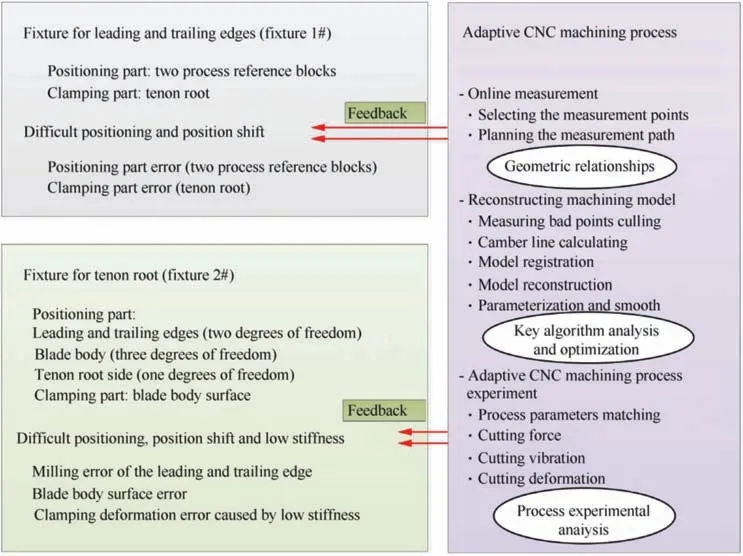
Fig. 2 Adaptive CNC machining process and main fixtures.
Adaptive CNC machining technology has two parts:online machine measurement and machining model reconstruction(see Fig. 2). Measurement points for online machine measurement should be selected based on geometric relationships to reflect the blade characteristics, and the measurement path should be planned based on the selected points to obtain the optimal measurement track. A new CNC machining model should be reconstructed based on the measurement and theoretical models. First, the measuring bad points should be culled out to ensure useful measurement points that can reflect the blade geometry.Second,the measurement model should be based on the measurement points,and the corresponding geometric parameters,such as camber line,chord length,and radii of leading and trailing edges, should be calculated. The corresponding theoretical model is established based on the design model, and its geometric parameters are calculated. Third,model registration is conducted based on the established theoretical and measurement models to obtain the geometric relationship between them. Fourth, the CNC machining model is reconstructed based on the geometric relationship. Finally,the reconstructed machining model is parameterized and smoothed.Based on this adaptive CNC machining technology,the benchmarks, including for measurement, machining, and modeling, will become a unified benchmark. The positioning problem caused by the positioning error due to poor accuracy of the precision forging process is systematically solved and will no longer be considered in fixture design; the fixture will become more targeted and will only be used to firmly clamp the blade and ensure a stable cutting process.It will reduce cutting deformation and vibration to enable the solution of the problem of low stiffness. The key technical issue is how to ensure that the blade is not damaged, based on improving the stiffness of the blade-fixture system and the clamping stability in the cutting process.
Based on the above analysis, it is clear that the difficult problems and challenges of CNC machining of a near-netshaped blade are difficult positioning and low stiffness. The problem of positioning difficulty is solved by adaptive CNC machining algorithms and online measurements, and that of low stiffness by optimized design.
Specifically,in a real adaptive CNC machining process,the NC program can compensate for the positioning error through online measurement of workpiece position/shape, which will lead to the change of the design and evaluation criteria of a fixture.Positioning error control will not be important,while the blade deformation control will be the main problem which needs to be considered in fixture design and adaptive CNC machining process matching. The fixture for adaptive CNC machining generally has three aspects.One is the overall deformation of the blade and clamping heads, which can be compensated for by machining model reconstruction by translation and rotation. Another is the maximum deformation of the blade and clamping heads, which is caused by improper operation and unreasonable magnitude and sequence of clamping forces. This local deformation of a certain part of the blade affects the accuracy of the registration algorithm and machining model reconstruction. Therefore,clamping forces should be reasonably optimized to minimize deformation of the blade and clamping heads.Third is stiffness of the blade-fixture system. This occurs because the adaptive CNC machining process weakens the positioning function and places more emphasis on the clamping capacity.
To sum up, the new fixture-evaluation criteria and method for adaptive CNC machining process fixture design consist primarily of overall deformation, maximum deformation, and system stiffness.
3. Machining fixture for the adaptive CNC machining process
Fixtures for adaptive CNC machining should have specific structural feature and material characteristics. The fixture structure has three main parts,as shown in Fig.3:1)the fixture base is used as a support base and is always connected to the machine tool; 2) the positioning subassembly provides accurate positioning to the workpiece; and 3) the clamping subassembly ensures stability. The clamping subassembly has two independent clamping units, each with one actuator and two clamping heads to pressure the blade body.

Fig. 3 Basic structure of fixture.
Nine positioning (or assistant positioning) heads contact the blade body. There are three auxiliary positioning points based on the original six-point positioning of the fixture to increase the stiffness of the blade-fixture system, which can better clamp the blade and resist deformation caused by cutting force, and all these positioning points are based on the precision forging process coordinate system (XC, YC, ZC)which is also the coordinate system of the 3D model (see Fig. 4(a)).
1. Positioning points1# and 2# are in position line 8#.
2. Positioning points 3#and 4#,which are in position line 2#,form a rotary motion pair with only one degree of freedom that increases system stiffness while avoiding overpositioning. Therefore, positioning points 1#, 2#, 3#, and 4# fix three degrees of freedom of a plane. The accuracy of position lines 2#and 8#is controlled in the forging process of the blade,which is complex due to the free-form surface blade structure and the difficulty of molding TC4 titanium alloy material. The accuracy of precision forging is approximately 0.1-0.2 mm, and the accuracy of those two position lines is less than 0.1 mm.So,the main location points of the blade surface should be distributed on those two position lines (see Fig. 4(a)).
3. Positioning point 5# fixes a degree of freedom of a plane.
4. Positioning points 6#and 7#fix two degrees of freedom of a plane. Positioning points #8 and #9 are used not to limit the degree of freedom but to prevent the blade from swaying. There is a gap of 1.0 mm between the blade and positioning points 8# and 9# (see Fig. 4(b)).
Therefore, there are nine positioning points, different from the six positioning points for determining a plane. However,this is not an over-positioning scheme, as the auxiliary positioning points are only used to improve the stiffness of the blade-fixture system.
The clamping force is generated by the compression adjustment screw,transmitted to the active pressure plate via a hinge structure, and finally transmitted to the active pressure head through two independent hinges to the clamp block. This structure distributes pressure more uniformly, and the pressures of the two active pressure heads are equal when ignoring the frictional force, as shown in Fig. 5.
The main structural components of the fixture are made of steel, the clamping heads and positioning heads are made of polyetheretherketone (PEEK-GF30) material, and the blade’s main material is Ti-6Al-4V, as shown in Table 1.
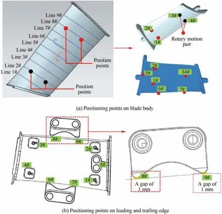
Fig. 4 Positioning scheme of fixture.

Fig. 5 Clamping scheme of fixture.

Table 1 Material properties of blade and fixture components.
4. Conditions and methods
New fixture-evaluation criteria for adaptive CNC machining include the overall deformation, maximum deformation, and system stiffness. The overall deformation of the blade and clamping heads can be described by deformation and a stress cloud map obtained by FEA, the maximum deformation can be described by a mathematical model of the clamping forces and deformation, and the stiffness of the blade-fixture system can be analyzed by modal testing and FEA. The analysis flow is shown in Fig. 6, and the analysis and experimental process are as follows.
Step 1:Calculate the overall deformation,maximum deformation,and modal frequency of the blade-fixture structure by FEA based on the ANSYS platform. The numbers of nodes and elements of the blade-fixture system are listed in Table 2,and the material parameters of the blade,clamping heads,and positioning heads are shown in Table 1.
Most important is to emphasize boundary conditions. As shown in Fig. 7, there are 13 elastic surface contacts betweenthe blade and fixture components, consisting of positioning points and assistant positioning points.Positioning points support and position the blade, B={Li|i=1 ~5}. There are four assistant positioning points on leading and trailing edge surface of the blade, C={Li|i=6 ~9}, which can restrict the potential slip of the workpiece under clamping and cutting forces. At the clamping points of the fixture, A={Ci|i=1 ~4},are clamping pressures Fcuc,where Fcis the clamping force vector, and ucis the direction (to the blade surface)vector. To illustrate the relation between clamping forces and deformation, four clamping forces are loaded according to an orthogonal test, as shown in Fig. 8. Assuming that the surface of each positioning head on the fixture base is fixed,the displacements of all points on the surface are Uxyz=0.
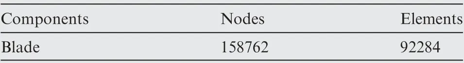
Table 2 Number of nodes and elements of the blade-fixture system.

Fig. 6 Fixture analysis flowchart.
Step 2:Test the clamping forces and deformation.The laboratory equipment includes the following. A thin-film force sensor measures clamping force; a torque wrench tightens the bolt and clamp blade. An eddy current sensor measures the relative displacement variation.This non-contact linearized measurement sensor can measure the distance between the metal conductor and the probe surface by static and dynamic non-contact, with high linearity and high resolution.
The clamping force and deformation test site is shown in Fig.8.The bolt is tightened by a torque wrench,and clamping forces are simultaneously recorded by a film force sensor.This process can be adjusted repeatedly until the clamping force takes a specific value. As mentioned above, the positioning heads and clamping heads are made of PEEK-GF30 material with a typical rigid-flexible coupling model, and the eddy current sensor can only obtain the displacement signal of the observation point in experiments, which can reflect the response ability of the fixture under clamping forces and cutting forces.The fixture used in this experiment is manufactured by Xi’an Aero-Engine (Group) Ltd.
Step 3:The stiffness of the blade-fixture system is an important indicator to evaluate a fixture for the adaptive CNC machining process, and it can be expressed by modal frequency.Modal analysis is necessary, and the modal frequency obtained by FEA should be verified by experiments.Therefore,modal tests of the blade-fixture system under different clamping forces are essential. An acceleration sensor (Dytran 3225 M23) measures the system’s dynamic response; its sensitivity is 49.7 mV/g, which ensures a sufficient sampling frequency to obtain the displacement response signal. A hammer (Dytran 5850B) with sensitivity 2.5 mV/N is used to tap the blade-fixture system. A film force sensor measures clamping forces. The mapping relationship between clamping forces and modal frequencies of the blade-fixture system is analyzed after obtaining the modal frequencies under different clamping forces. An LMS data-acquisition system, with eight data acquisitions (DAQ) module slots for four-channel dynamic signal inputs, collects the displacement response signal of the blade-fixture system from the acceleration sensor.
The modal test site is shown in Fig.9.The bolt is tightened by a torque wrench, the clamping forces are simultaneously recorded by the film force sensor,and the four clamping forces(F1, F2, F3, and F4) are adjusted to near 200, 400, 600, 800,1000 N.Modal experiments are conducted with each clamping force to obtain the corresponding natural frequencies. Five modal frequencies are obtained by FEA with the measured clamping forces.The simulation analysis and experimental test frequencies are analyzed and summarized.

Fig. 7 Simplified analysis model and boundary conditions.
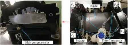
Fig. 8 Clamping force and displacement test site.
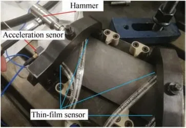
Fig. 9 Test site of modal test.
Step 4: A cutting experiment and fixture application are used to verify the feasibility of the fixture. During the cutting experiment, an emulsion-cooling vertical machining center(KIV Hi-CENTER H40) is used to mill the blade. The working temperature of this four-axis milling machine tool is 20°C.The hard-alloy flat-end cutter has four teeth, and its diameter is 16 mm,and the tenon root can be milled to a plane with flatness of 0.07 mm. A Kistler rotary dynamometer measures the cutter force.This Kistler rotary dynamometer can be mounted on the shank to test its force.The cutting force measured from the shank can more directly reflect the interaction force between the cutter and blade relative to the Kistler 9255B dynamic piezoelectric dynamometer. This is because Kistler 9255B dynamic piezoelectric dynamometer tests the cutting force after transfer process, and this cutting force produces between the cutter and blade, and then to the fixture, and finally to the test platform. A Kistler 5017A charge amplifier and HBM data-acquisition and processing system are used to collect cutting forces.MATLAB software is used to process the cutter-force signals, including filtering and numerical calculations.
The cutting experiment and fixture application proceed as follows. The blade is clamped according to the proposed clamping scheme, and the relative displacement variation during the clamping process is measured by the electrical vortex sensor. Milling experiments, including roughing milling and finishing milling, are conducted. The machining parameters are shown in Table 3. The cutting force is tested by a Kistler rotary dynamometer, and the relative displacement variation is measured by an electrical vortex sensor. The relationship between cutting force and displacement is analyzed. The schematic diagram is shown in Fig. 10. The sample frequency ofcutting force data is 25,000 Hz, and sample frequency of the electrical vortex sensor is 1024 Hz. The cutting force and relative displacement variation test is conducted under stable cutting conditions, and each group of tests is conducted three times for consistency.
5. Results and discussion
5.1.Analysis of overall deformation of blade and clamping heads
Fig.11 shows the deformation of the blade and each clamping head obtained by FEA, and the corresponding stress is shown in Fig.12.The clamping forces(F1,F2,F3,and F4)are 500 N in this case. It can be seen in Fig. 11 that deformation occurs in the four positioning heads, and the blade incurs displacement change rather than local deformation. This phenomenon can be explained by blade stress. Fig. 12 shows that there is no stress concentration in the blade, whose stress is close to zero,and the stress of the PEEK-GF30 clamping heads and positioning heads exceeds the blade stress, which indicates that the deformation mainly occurs at the clamping and positioning heads. The maximum deformation of the blade-fixture system is 0.0525 mm, and the average deformation is around 0.028 mm.
However, if the clamping and positioning heads are made of steel,there will be serious local deformation and stress concentration in the blade, especially near the clamping heads.The clamping heads show less stress than the blade,indicating that the deformation occurs at the blade.The maximum deformation is 0.0026 mm, and the average deformation is around 0.0017 mm, which is far less than the deformation of steel clamping and positioning heads. Therefore, this positioning and clamping method can accurately position the blade, but it will badly damage the blade through stress concentration.
It is an obvious contradiction that the clamping heads and positioning heads are both easy or difficult to deform. If the clamping and positioning heads are difficult to deform, the blade will be priority to deform, which will lead to small defects on the airfoil surface and affect the service life and reliability of final blade, especially for the thin-walled complex curved blade in the case of high clamping pressure.Conversely,easily deformed clamping and positioning heads enable better blade protection and improve the service life and reliability of the final blade but are bad for accurate positioning due to positioning error caused by the deformation of positioning heads.We prioritize the protection of the blade from damage,and the inaccurate positioning will be compensated by the adaptive CNC machining technology. Therefore, the problems of positioning and low stiffness will be solved by designing a reasonable fixture and matching suitable adaptive CNC machining process.

Fig. 11 Deformation cloud map of blade and each clamping head.

Fig. 12 Stress of blade and each clamping head.
5.2. Effect of clamping forces on maximum deformation
Four factors and three levelsof orthogonal simulation analysis are designed to analyze the coupling effect of clamping forces on the maximum deformation.Four main clamping forces affect deformation. These are F1(denoted as A), F2(denoted as B), F3(denoted as C), and F4(denoted as D).The distribution of these forces on the blade surface is shown in Fig. 8, and the test factor level is shown in Table 4.
To research the influence of clamping forces on the maximum deformation enables the understanding of the interaction rule between clamping forces and maximum deformation.Most widely used is the response surface method, wherebythe clamping force combination is designed by a central composite method.The maximum deformation is shown in Table 5.

Table 4 Level of factor distribution of clamping forces.
The maximum deformation prediction model is nonlinear,considering that the maximum deformation is influenced by the coupling effect of clamping forces rather than a single force. Therefore, a quadratic regression design is selected for this study:

Table 5 Orthogonal experimental design and test results.

where Y is the predicted maximum deformation, d is the maximum deformation, ε is the error, b is the model coefficients,and x is the level of clamping force.
The coefficient matrix can be calculated as

where X is a matrix composed of the experimental variables,and β is a matrix of the experimental results.
The maximum deformation prediction model for the clamping forces is established according to Eq.(2).The multiple regression model between the maximum deformation and clamping forces is established by converting the experimental parameters and results in matrix form and combining the least squares regression approach. The final prediction model isThe desired confidence level for ANOVA is considered to be 95%.The model F value of 489.09 shows that the model is significant. The F test with a very low probability value (P value Prob >F=0.0001) shows a high significance of the regression model, as shown in Table 6.

Table 6 ANOVA table for the regression model.
To analyze the coupling effect of clamping forces on the maximum deformation, the zero-level values of two clamping forces are substituted in the empirical model, the other two clamping forces are used as the variables,and the response surface of the clamping forces to the maximum deformation can be obtained, as shown in Fig. 13.
It can be seen in Fig. 13(a)that the maximum deformation gradually increases as F1and F2increase, and F1has a more significant effect than F2. Fig. 13(b) shows that the maximum deformation gradually increases as F1and F3increase, and F1has a more significant effect than F3.It can be seen in Fig.13(c)that the maximum deformation gradually increases with F4and is almost unchanged as F1increases;F4has a more significant effect than F1.Fig.13(d)shows that the maximum deformation gradually decreases as F2and F3increase,and F3has a more significant effect than F2.It can be seen in Fig.13(e)that the maximum deformation gradually decreases as F4increases and is almost unchanged as F2increases;F4has a more significant effect than F2.Fig.13(f)shows that the maximum deformation gradually increases as F4increases and is almost

To test the significance of the maximum deformation prediction model, variance (ANOVA) analysis, residual analysis,and comparison of actual and predicted value are conducted.
unchanged as F3increases;F4has a more significant effect than F3.Therefore,the maximum deformation is mostly sensitive to F4, followed by F1, F3, and F2.
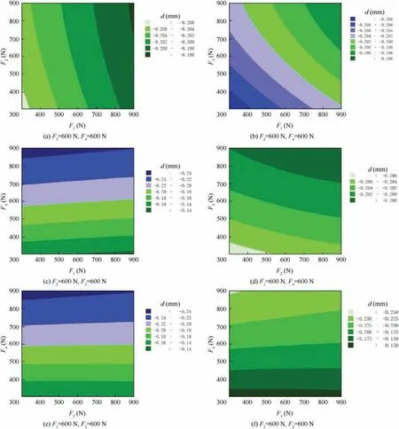
Fig. 13 Contour plot of maximum deformation.
5.3. Analysis of empirical model and clamping sequence
Sensitivity is the degree of maximum deformation to clamping forces. It can be determined by the sensitivity value of clamping forces, which are recognized as significant or insignificant.Therefore, the clamping forces can be effectively and accurately controlled and can be effectively optimized by the sensitivity analysis.If the objective function is f(x),and its variables are x=(x1, x2, xi, ..., xn), then if f(x) is derivable, the sensitivity can be calculated as

where f(x)is objective function,and its variables is x=(x1,x2,xi,...,xn).S(xi)is sensitivity of maximum deformation to variable of xi.
According to the definition of sensitivity, the sensitivity of the maximum deformation to clamping forces is calculated as

Relative sensitivity reflects the sensitivity degree of the maximum deformation to clamping forces. Relative sensitivity is compared under a uniform dimension and is expressed as

where f(x)is objective function,and its variables is x=(x1,x2,xi,...,xn).S(xi)is sensitivity of maximum deformation to variable of xi, S′ ( xi) is relative sensitivity of cutting force to variable of xi.
Relative sensitivity is defined by the absolute value of the relative change ratio between the objective function and variable:

The final relative sensitivity is

To determine the sensitivity order of the maximum deformation to the four clamping forces, the average value of the relative sensitivity of the whole interval is obtained by the median integral value of the relative sensitivity function, which is calculated as
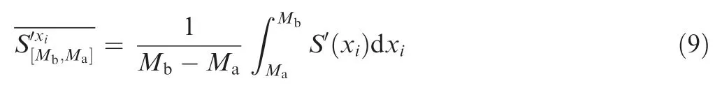
where Maand Mbare,respectively,the lower and upper limits of the interval, with respective values of 300 N and 900 N in this case.is the average value of the relative response S′(xi) in the interval of [Ma, Mb], and is calculated as:
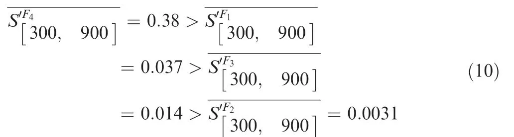
Therefore,the maximum deformation is mostly sensitive to F4,followed by F1,F3,and F2,and this result is consistent with the results of the response surface analysis in Fig.13.In Fig.14(a),the sensitivity of the maximum deformation to F1increases with F1, and this value in the interval [600,900] is higher than in the interval[300,600],so the stable range of F1is[300,600].In Fig. 14(b)-(d), the sensitivity of maximum deformation to F2, F3, and F4first increases and then decreases with the increase of F2, F3, and F4, and this value in the interval [300,600]is higher than in the interval[600,900],so the stable range of F2, F3, and F4is [600, 900].
Based on this, an alternating clamping method should be used, and this process is divided into two stages. First is to adjust the four clamping forces to be within a range around the target value, and second is to control clamping forces soas to strictly equal the target value. For example, assume the target value is 600 N.In the first stage,as a roughing clamping stage,each clamping force should be adjusted within its stable range. F1should be in the range [600-δ,600], whereδ is a small clamping force. F2, F3and F4should be in the range of[600,600+δ].In the second stage,as a precise clamping stage,F3and F2are not sensitive and should be a priority to tighten,and then F1, and finally F4. F1and F4should be strictly controlled and adjusted slowly.The clamping sequence and stable range are shown in Table 7.

Table 7 Stable range and clamping sequence.
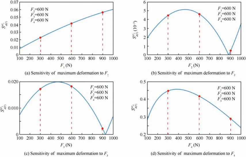
Fig. 14 Sensitivity of maximum deformation on clamping forces.

Fig. 15 Result of modal frequency.
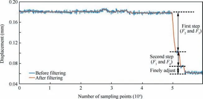
Fig. 16 Displacement change during the clamping process.

Fig. 17 Test results of cutting force in the roughing milling process.
5.4. Effect of clamping force on fixture stiffness
Fig. 15(a) shows the modal frequency of the blade-fixture system obtained by FEA and experiment when the clamping forces are near 200 N. Fig. 15(a) shows that the first-order natural frequency obtained by the modal test is 805 Hz.Fig. 15(b) shows that the first-order natural frequency obtained by FEA is 794.5 Hz, which is less than the measured natural frequency;however,the error between FEA and experiment is less than 5%. Therefore, FEM can reasonably reflect the dynamic characteristic of this fixture-blade system. The first-order natural frequency when clamping forces are near 400 N is 840 Hz (see Fig. 15(c) and (d)), when the clamping forces are near 600 N is 860 Hz (see Fig. 15(e) and (f)) when the clamping forces are near 800 N is 870 Hz (see Fig. 15(i)and (g)), and when the clamping forces are near 1000 N is 910 Hz(see Fig.15(i)and(j)).Stiffness of the blade-fixture system will increase by 20 Hz when each clamping force is increased by 200 N. Therefore, system stiffness can be enhanced by adjusting clamping forces in actual blade production.
5.5. Cutting experiment and application of fixture
The alternating clamping method can decrease the maximum deformation and securely clamp the blade. The first stage is to adjust the four clamping forces to be within a range around the target value, and the second is to control the clamping force to strictly equal the target value, which is 600 N in this case. In the first stage, as a roughing clamping stage, each clamping force should be adjusted within its stable range.Specifically:
F2should be adjusted in the range of[600,600+δ],where δ is a small amount of clamping force. The maximum displacement should occur in this process because the maximum deformation is mostly sensitive to F4, followed by F1, F3and F2, and the stable range of F2is [600, 900].
F3should be adjusted in the range of[600,600+δ],and the displacement is less than in Step 1.
F1should be adjusted in the range of[600-δ,600],and the displacement is less than in Step 2.
F4should be adjusted in the range of[600,600+δ],and the displacement is less than in Step 3.Finely adjust the four clamping forces to the target value.
In practice, the two forces are best adjusted at the same time to maintain balance and reduce distortion. In this experiment, the displacement signal of the observation point obtained by the eddy current sensor can reflect the response ability of the fixture under the clamping and cutting forces.Both F2and F3are adjusted at the same time to the appropriate range, as shown above, the corresponding clamping forces can be obtained by a film force sensor, and the displacement signal is recorded by an eddy current sensor. Both F1and F4are then adjusted at the same time to the appropriate range,and the clamping forces and displacement signal are recorded similarly. Finally, the four clamping forces are finely adjusted to the target values. The test results are shown in Fig. 16.The displacement of 0.08 mm in the first step(adjusting F2and F3)is larger than in the second step(adjusting F1and F4),which is 0.03 mm. The displacement in the step of fine adjustment is 0.01 mm, which is very small relative to the first and second steps. Therefore, the above clamping method can effectively control the deformation of the blade.
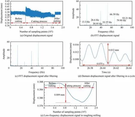
Fig. 18 Test results of displacement in the roughing milling process.

Fig. 19 Test results of cutting force in the finishing milling process.
To verify the feasibility of the fixture and further apply it to the cutting process of the blade, a milling experiment on the blade is conducted, and the cutting force and displacement are measured,including roughing milling and finishing milling.The main machining parameters are shown in Table 3.
Fig. 17 shows the test results of cutting force in roughing milling,and Fig.18 shows the corresponding displacement signal under the same process parameters. To analyze the correspondence between the cutting force and displacement and evaluate the responsiveness of the fixture under cutting force,FFT is used to analyze the cutting force and cutting displacement signals. Fig. 18(a) shows the domain signal of cutting force in a cycle.An eddy current sensor with high sampling frequency and high resolution is used because the displacement in cutting is at the level of 0.001 mm, there is high-frequency noise in the cutting displacement signal due to the complexity of the cutting environment and the interference of other equipment,and there is an electrical surge voltage signal that should be removed. Therefore, FFT analysis and filtering are required. Fig. 18(a) shows the displacement signal measured by an eddy current sensor. Fig. 18(b) shows the FFT signal of displacement. The displacement signal is filtered to emphasize the response signal of the main cutting force,and only the displacement signal whose main frequency corresponds to the cutting force is left to analyze the response of the cutting force under a specific fixture, and other displacement signals are filtered. Fig. 18(c) shows the FFT signal of displacement after high-frequency filtration.Signals with a frequency greater than 50 Hz are filtered out because the main frequency of the cutting force is less than 50 Hz. Fig. 18(d) shows the timedomain signal in one cycle after filtering, which corresponds to the cutting force. Fig. 18(e) shows the low-frequency displacement signal and cutting rebound in the roughing milling process. The displacement signal with the cutting process time can be considered a low-frequency blade-deformation signal at three stages: before cutting, during cutting, and springback after cutting; the trend over time can reflect the deformation of the blade.The roughing milling curve is a displacement signal in the entire roughing milling process,the x-axis represents the number of points collected in the roughing milling process,and the y-axis represents the displacement value obtained through smoothing the collection points of the entire curve to observe its entire trend. The finishing curve is similarly obtained.
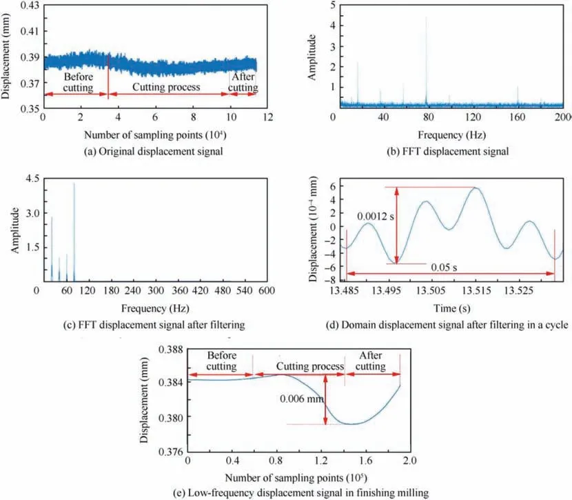
Fig. 20 Test results of displacement in the finishing milling process.
In the roughing milling stage,the resultant cutting forces in the x-,y-,and z-direction are in the range of 0-300 N,its RMS value is 132 N, and the main cutting frequencies are 13.3 Hz,26.6 Hz, 39.9 Hz, and 53.3 Hz. The displacement response of this blade-fixture rigid-flexible coupling system under the action of these cutting forces is shown in Fig.18.It can be seen that the main frequencies of the cutting-force and displacement signals are almost the same,and the response-displacement signal is a superposition of the vibration-displacement signal and deformation signal of the blade, which is composed of elastic and rigid displacements. A signal with the same cutting-force frequency can be understood to be a high-frequency signal,which can be considered a dynamic response signal caused by the cutting force. The displacement signal with time can be considered a low-frequency blade-deformation signal, with the three stages of before cutting, during cutting, and springback after cutting, and the trend with time can reflect the deformation of the blade, as shown in Fig. 18(e). The cutting force cycle is 0.075 s, which is closely related to the cutting spindle speed(800 r/min).In the roughing milling stage,a cutting force of RMS of approximately 132 N with a period of 0.075 s in this rigid-flexible coupling system of fixture blade produces a displacement response whose displacement is 0.012 mm, with a period of 0.075 s. The maximum deformation of blade is 0.009 mm during the before cutting, cutting process, and after cutting. This means that the maximum displacement during the cutting process is 0.009 mm, this displacement will rebound when cutting is completed, and it is an elastic displacement in this rigid-flexible coupling system due to the soft characteristic of PEEK-GF30.
In the finishing milling stage, as seen in Fig. 19, the resultant cutting forces in the x-, y-, and z-directions are in the range of 0-70 N, their RMS value is 35 N, and the main cutting frequencies are 20 Hz, 40 Hz, 60 Hz, and 80 Hz. Therefore, the displacement signals whose frequencies are in the ranges [0-19 Hz], [21-39 Hz], [41-59 Hz], [61-79 Hz], and [81 to +∞Hz] are filtered out, as shown in Fig. 20(c). It can be seen that the main frequencies of the cutting-force and displacement signals are almost identical. The cutting force cycle is 0.05 s, which is closely related to the cutting spindle speed(1200 r/min). In the finishing milling stage, a cutting force of RMS of approximately 35 N with a period of 0.05 s in this rigid-flexible coupling system of the fixture blade produces a displacement response of 0.0012 mm with a period of 0.05 s.The maximum displacement is 0.006 mm in the finishing process before, during, and after cutting (see Fig. 20(e)).
All of those displacements,as shown in Table 8,are acceptable for machining accuracy requirements of 0.1 mm. This shows that a reasonable fixture and adaptive CNC machining process can enable high-accuracy manufacturing of near-netshaped blades. This also indicates that the proposed fixture is reasonable and can be used in a blade-adaptive CNC machining process, and the fixture of rigid-flexible coupling is reasonable in protecting the blade from damage with small deformation during the cutting process. The fixture and pro-cessing methods described in this paper can provide a basis research and engineering application for high-precision manufacturing of near-net-shaped thin-walled blades.

Table 8 Measuring displacement value.
6. Conclusions
In this study, the machining fixture, clamping force, clamping deformation,and cutting displacement response in an adaptive CNC machining process of near-net-shaped thin-walled blades were investigated by theoretical analysis, FEA, and engineering experiments. The results can be summarized as follows.
1) The new fixture-evaluation criteria and method for an adaptive CNC machining process mainly include overall deformation, maximum deformation, and system stiffness.
2) The introduction of PEEK-GF30 material and a multipoint support structure is a meaningful attempt to manufacture a blade fixture, leading to the blade tenon root incurring 0.028 mm rigid deformation. The main deformation of the blade-fixture system occurs on the four clamping heads, and this fixture can effectively protect the blade from local deformation.
3) The relationship between the clamping forces(F1,F2,F3,and F4)and maximum deformation is analyzed by FEA and orthogonal experiments, and the empirical model between the clamping forces and maximum deformation is established. A reasonable clamping sequence is obtained to minimize the maximum deformation. The maximum deformation is mostly sensitive to F4, followed by F1, F3, and F2; the corresponding clamping sequence is F2, F3, F1, and F4; and F4and F1must be precisely controlled. The clamping experiment shows that the proposed method to determine the clamping sequence by sensitivity and relative sensitivity is feasible and can be used to instruct workers to complete the clamping work in practice.
4) The stiffness of the blade-fixture system increases by 20 Hz when the clamping forces increase by 200 N,and the increase of clamping forces has little effect on the stiffness of this soft-rigid coupling system.
5) The cutting experiment shows that the fixture described in this paper can be used in the adaptive CNC machining process of near-net-shaped thin-walled blades, both high- and low-frequency displacement in roughing milling and finishing milling are acceptable,and this fixture and adaptive CNC machining technology have a strong application value in processing near-net-shaped thin-walled blades.
Acknowledgements
The author would like to acknowledge the support and contributions of our colleagues in Xi’an Aero-Engine (Group)Ltd. This research is supported in part by Xi’an Aero-Engine(Group) Ltd., National Key Scientific Instrument and Equipment Development Project(2016YFF0101900),National Natural Science Foundation of China (Grant 51575310) and Beijing Municipal Natural Science Foundation (Grant 3162014).
杂志排行

CHINESE JOURNAL OF AERONAUTICS的其它文章
- Reliability and reliability sensitivity analysis of structure by combining adaptive linked importance sampling and Kriging reliability method
- Aeroelastic dynamic response of elastic aircraft with consideration of two-dimensional discrete gust excitation
- Thermal damage analysis of aircraft composite laminate suffered from lightning swept stroke and arc propagation
- An aerospace bracket designed by thermo-elastic topology optimization and manufactured by additive manufacturing
- Applications of structural efficiency assessment method on structural-mechanical characteristics integrated design in aero-engines
- An energy-based coupling degradation propagation model and its application to aviation actuationsystem