Effects of tooth bending damage on the leakage performance and rotordynamic coefficients of labyrinth seals
2020-06-11YoxingCHENZhigngLIJunLIXinYAN
Yoxing CHEN, Zhigng LI, Jun LI,b,*, Xin YAN
a Institute of Turbomachinery, Xi’an Jiaotong University, Xi’an 710049, China
b Collaborative Innovation Center for Advanced Aero-Engine, Beijing 100083, China
KEYWORDS Labyrinth seal;Leakage;Rotor forward whirl;Rotordynamic coefficients;Tooth bending damage;Vena contracta effect
Abstract Tooth bending damage resulting from an intense impact by the rotor sometimes occurs in the transient operation.To investigate the influence of after-damage clearance and tooth bending length on the leakage performance and rotordynamic coefficients of labyrinth seals, three tooth bending damages were taken into consideration, including the unbent tooth damage (abbreviated as Unbent),the partial tooth bending damage(abbreviated as Pbent)and the complete tooth bending damage (abbreviated as Cbent). The transient CFD solution was utilized to calculate the leakage flow rates and rotordynamic coefficients of labyrinth seals with clearances of 0.3, 0.4, 0.5,0.6 mm for three tooth bending damages.The obtained result shows that the Unbent tooth damage leaks least while the Pbent tooth bending damage leaks most, and an increase of 6.1% for Cbent tooth bending damage and an increase of 19.4% for Pbent tooth bending damage are discovered at the tooth clearance of 0.6 mm in comparison with the Unbent tooth damage. Compared to the Unbent tooth damage,the effective damping for Pbent tooth bending damage and Cbent tooth bending damage is lower and drops by 9.7%-33.6% and 8.5%-22.6% respectively at the tooth clearance of 0.6 mm,suggesting that Pbent tooth bending damage or Cbent tooth bending damage tends to weaken the seal stability when compared to the Unbent tooth damage.
1. Introduction
Annular gas seals play an important role in the internal air system of modern gas turbines to restrict the leakage and improve engine efficiency.1However, tooth damage sometimes occurs in the transient operation, such as start-up, shut-down and hot-restart,which will increase the tooth clearance and change the tooth shape, resulting in a larger leakage and a dropped engine efficiency.2The after-damage tooth shape,such as tooth mushrooming and tooth bending, mainly depends on two factors:the tooth hardness and the operation condition.3For the labyrinth seal with tooth on stator, tooth made of any metal would bend in various degrees when an intense impact by the rotor occurs.3
In the open literature, limited information is concerned with the investigation of tooth bending in annular gas seals.Xu et al.3numerically quantified the influence of afterdamage clearance, bending angle and bending radius on the leakage of after-bend labyrinth seals, and found that the leakage increase induced by tooth bending was mainly ascribed to the increased after-damage clearance. Yan et al.4investigated the effects of tooth bending on the flow fields of the labyrinth seal.
Although manifold investigations on the rotordynamic coefficients of labyrinth seals with different geometrical structures have been conducted, the research regarding rotordynamic behavior induced by tooth bending in labyrinth seals is seriously lacked. Huang and Li5-7employed the transient CFD solution with moving boundaries to predict the rotordynamic coefficients of straight-through labyrinth seals, and pointed out that the accuracy of predictions could be improved by introducing a non-linear model of aerodynamic force and coupling fluid-solid vibration of the rotor. Xia et al.8calculated the rotordynamic coefficients of smooth annular seals utilizing a transient bulk flow model. Cangioli et al.9investigated the effects of upstream and downstream regions of annular gas seals on rotordynamic coefficients. Yang and San Andres10discussed the influence of the shape of entrance section on the rotordynamic performance and observed that the direct damping for the round inlet decreased by 10% compared to the sharp edge inlet. Wang et al.11compared the stability of three groove-on-stator labyrinth seals: no groove,tooth in the middle of the groove and tooth in the upstream of the groove, and found that the labyrinth seal was most stable when the tooth was arranged in the middle of the groove. Mortazavi and Palazzolo12investigated the leakage and rotordynamic performance of a groove-on-rotor annular liquid seal, and they found that the stability characteristics of the labyrinth seal would be reduced when the grooves on the rotor were introduced; however, a superior performance was also shown at higher pressure drop in terms of the leakage.Furthermore, in Mortazavi and Palazzolo’s work, roughness was demonstrated to be crucial in deciding the leakage and the stiffness.Zhang et al.13investigated the fluid-induced excitation force of a new kind of radial annular seal, and found that the tangential force of the radial annular seal dropped about 30%-50% than that of the common axial annular seal.Li et al.14researched on the static stability of pocket damper seals,disclosing that the magnitude of cross-coupling response forces acting on the rotor increased with eccentricity ratios.Meanwhile, Li et al.15investigated the rotordynamic stability of three labyrinth seals: the tooth-on-stator labyrinth seal,the tooth-on-rotor labyrinth seal and the interlocking-tooth labyrinth seal. Xi and Rhode16discussed the cause-effect relationship between various teeth tip geometries and seal rotordynamics for a typical impeller eye seal,and pointed out that the tip geometries considered for the wear-damaged teeth had a negligible effect on the rotordynamic coefficients. In recent work,17the tooth tip mushroom radius was found to influence the seal stability remarkably when the frequency dependence of rotordynamic coefficients was considered.
To obtain a detailed insight of the effect of tooth bending on the leakage and rotordynamic performance, the leakage flow rates and rotordynamic coefficients are presented and analyzed for labyrinth seals with three tooth bending damages and four after-damage clearances.
2. Computational model
The unbent labyrinth seal with the original clearance of 0.3 mm was chosen from Ref.18. The tooth number was designed to be 6. The bending model proposed by Xu et al.3was adopted in this work. Fig. 1 gives the schematic view of a tooth before bending damage (broken lines) and after bending damage (solid lines). Notably, three assumptions3were used in this bending model:the first one was that the tooth center line is an arc with particular radius,the second assumption was that the arc of centerline is tangential to the centerline of unbent portion, and the third assumption was that there is no change of tooth thickness between pre-bend teeth and afterbend teeth at the equal length of the centerline. With these three assumptions, the bending parameters (including the arc radius Rband arc angle β)are only determined by two values:the location where bending starts (denoted by U) and afterdamage clearance (denoted by Cad). When the bending length keeps constant,the bending angle increases with an increasing after-damage clearance while the bending radius drops with an increasing after-damage clearance. Detailed introduction about the bending model can be found in the Ref.3.
In Fig. 1, Wris the thickness of the tooth root, Wtis the thickness of the tooth tip,H is the cavity depth,Ltis the height of the pre-damage tooth,δ is the angle at an arbitrary location,Cpdis the pre-damage clearance.
In order to investigate the effects of the after-damage clearance and tooth bending length on the leakage and rotordynamic performance, the unbent tooth damage (U/Lt=1,abbreviated as Unbent), the partial tooth bending damage(U/Lt=0.5, abbreviated as Pbent) and the complete tooth bending damage(U/Lt=0, abbreviated as Cbent) were taken into consideration. Table 1 lists the detailed geometrical parameters for three tooth bending damages. Figs. 2-4 show teeth geometries with various clearances changing from 0.3 mm to 0.6 mm for three tooth bending damages.
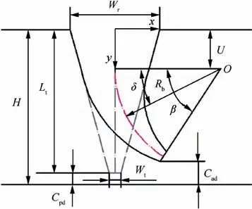
Fig. 1 Tooth geometry before and after bending damage.

Table 1 Geometrical parameters for three tooth bending damages.
The computational model and meshes of labyrinth seals with after-damage teeth are shown in Fig. 5. The multi-block structural meshes were adopted and O-type grids were imposed in the near-wall regions.In particular, extra O-type grids were arranged around the leading edge for labyrinth seals with Pbent tooth bending damage to guarantee a good mesh quality.
3. Numerical method
A transient CFD solution based on the multi-frequency elliptical orbit rotor whirling mode and dynamic mesh technique19,20was used to calculate the leakage flow rates and rotordynamic coefficients of labyrinth seals with an original clearance of 0.3 mm and another three after-damage tooth clearances of 0.4 mm,0.5 mm,0.6 mm for Unbent tooth damage, Pbent tooth bending damage and Cbent tooth bending damage, respectively. Table 2 gives an elaborate numerical method introduction about the transient approach. The inlet total pressure and inlet total temperature imposed were 690 kPa and 14°C, respectively. The outlet average pressure was 383 kPa and the rotational speed was 15,000 r/min. For the multi-frequency whirling model, the vibration frequency f ranging from 20 Hz to 260 Hz contained the subsynchronous and synchronous frequencies (≤250 Hz). The vibration amplitude a and b were chosen to be 1% and 0.5% of the predamage clearance. More detailed introduction to operation steps, convergence criteria in the transient solution approach and the determination methods of the rotordynamic coefficients can be found in the Refs.19,20.
The transient solution approach adopted in this work was validated by comparing the rotordynamic coefficients with Ref.20and test based data (EXP)18for a long unbent straight-through labyrinth seal as plotted in Fig. 6.Compared to the Ref.20,the inlet and outlet regions of the labyrinth seal in the experiments were considered when calculating rotordynamic coefficients in this work. As shown in Fig. 6, the predicted direct stiffness Kxxagrees well with the experimental data. The predicted cross-coupling stiffness Kxyand direct damping Cxxare significantly under-estimated. The predicted effective damping Ceffdiffers with experimental data less than 30% at frequencies above 120 Hz. These prediction errors are likely to be attributed to the difference in the velocity distribution adopted at the seal entrance between the CFD and the experiments. On the other hand, the predicted rotordynamic coefficients are more accurate in comparison with Ref.20,especially for the direct stiffness. In general, the transient solution approach has reasonable accuracy in terms of predicting rotordynamic coefficients of labyrinth seals and can be used for further studies.
To exclude the influence of the computational mesh on the obtained results, three different meshes were generated and calculated at the maximum clearance of 0.6 mm for three tooth bending damages. For Unbent tooth damage, three different grid nodes were 1.99 million, 4.28 million and 6.31 million.For Pbent tooth bending damage, three different grid nodes were 4.04 million, 5.77 million and 7.50 million. For Cbent tooth bending damage, three different grid nodes were 2.28 million,4.77 million and 7.00 million.Fig.7 illustrates the predicted cross-coupling stiffness Kxyand direct damping Cxxobtained at three different meshes and three tooth bending damages.As shown in the Fig.7,the direct damping is slightly weakened and the cross-coupling stiffness possesses a minor increase at frequencies below 180 Hz when the grid number increases. On the other hand, the obtained results show that the leakage at the maximum tooth clearance of 0.6 mm is practically independent of the mesh size for three tooth bending damages.Therefore,4.28 million nodes for Unbent tooth damage, 5.77 million nodes for Pbent tooth bending damage and 4.77 million nodes for Cbent tooth bending damage were chosen in this work.
4. Results and discussion
4.1. Leakage flow rate

Fig. 2 Unbent tooth damage.

Fig. 3 Pbent tooth bending damage.

Fig. 4 Cbent tooth bending damage.

Fig. 5 Computational model and mesh of labyrinth seals with three tooth bending damages.
Fig.8 shows the leakage flow rate as a function of tooth clearance for three tooth bending damages.As shown in Fig.8,the leakage increases with an increase in the tooth clearance for three tooth bending damages. The leakage flow rate in an ascending order is Unbent tooth damage,Cbent tooth bending damage and Pbent tooth bending damage, and this can be explained by Mach number contours or vena contracta effects among three tooth bending damages later.Meanwhile,the discrepancy of the leakage flow rate among three tooth bending damages increases when the tooth clearance enlarges. An increase of 6.1% for Cbent tooth bending damage and an increase of 19.4%for Pbent tooth bending damage are discovered at the tooth clearance of 0.6 mm compared to the Unbent tooth damage. Fig. 9 gives the Mach number (Ma) contours produced at the tooth clearance of 0.6 mm for three tooth bending damages. Compared to the Unbent tooth damage,Pbent tooth bending damage or Cbent tooth bending damage possesses a larger Mach number at the last tooth,and thus the labyrinth seal suffering Pbent tooth bending damage or Cbent tooth bending damage will lead to a larger leakage in comparison with the Unbent tooth damage.
As explained in the Refs.21,22,the vena contracta effect is of great importance in determining the leakage through labyrinth seals.In order to visualize this,streamlines near the first tooth region at the after-damage clearance of 0.6 mm are depicted for three tooth bending damages in Fig.10.For Unbent tooth damage, the effective flow clearance Craround the first toothregion is lower than the seal clearance Cadas a result of recirculation zone, and this is named vena contracta effect. The stronger vena contracta effect will contribute to a smaller effective flow clearance, and thus lead to a lower leakage.For Pbent tooth bending damage and Cbent tooth bending damage, the bent tooth shape helps the flow smoothly pass the leading edge of the first tooth and yield less vena contracta effect compared to the Unbent tooth damage. Normalized to the seal clearance, the effective flow clearances for Unbent tooth damage, Pbent tooth bending damage and Cbent tooth bending damage are around 0.80, 0.99 and 0.89, respectively,indicating a most leakage for Pbent tooth bending damage and a least leakage for Unbent tooth damage.
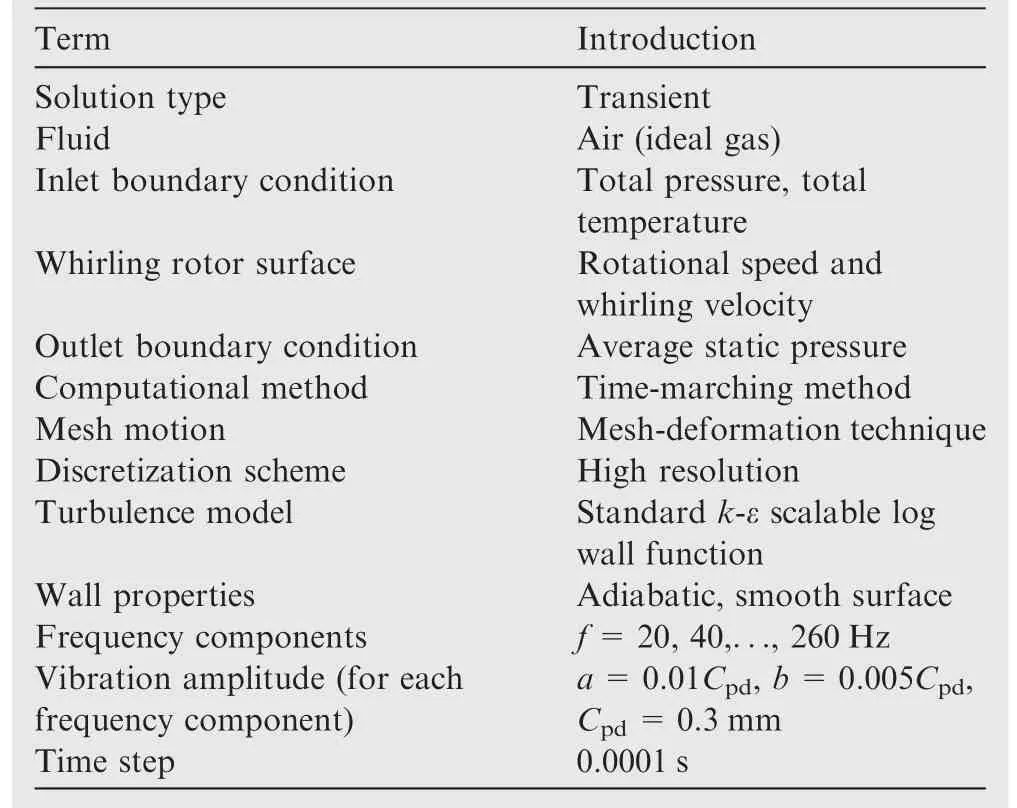
Table 2 Numerical method introduction about transient approach.
4.2. Direct stiffness
Fig. 11 illustrates the dependency of direct stiffness versus vibration frequency at four radial clearances for labyrinth seals with three tooth bending damages. For each tooth bending damage, the direct stiffness is positive. When the tooth clearance gradually enlarges without tooth bending damage, the direct stiffness increases and an increase of 67.9%-126.8%,23.1%-31.0 %, 17.1%-18.9% is obtained in an increased tooth clearance of 0.1 mm,respectively.When the tooth clearance enlarges with partial tooth bending damage or complete tooth bending damage,a similar increase in the direct stiffness is observed. However, a minute increase of less than 2.9% in the direct stiffness for Pbent tooth bending damage and an increase less than 6.3% in the direct stiffness for Cbent tooth bending damage are also observed as the tooth clearance changes from 0.5 mm to 0.6 mm. On the other hand, an obviously weakened frequency dependence for Pbent tooth bending damage and Cbent tooth bending damage at large tooth clearance(≥0.5 mm)is found in the direct stiffness in comparison with the Unbent tooth damage.
4.3. Cross-coupling stiffness
The cross-coupling stiffness is a crucial parameter when evaluating the rotor stability of labyrinth seals. The positive crosscoupling stiffness Kxywill produce the tangential force in the same direction with the whirling velocity and thus encourages the rotor forward whirl. On the contrary, the negative crosscoupling stiffness Kxywill generate the tangential force in the opposed direction with the whirling velocity and thus restrains the rotor forward whirl.
Fig. 12 shows the dependency of cross-coupling stiffness versus vibration frequency at four radial clearances for labyrinth seals with three tooth bending damages. For three tooth bending damages, the cross-coupling stiffness Kxyis negative even though the tooth clearance increases to 0.6 mm. Besides,the opposite sign and equal magnitude cross-coupling stiffness Kxy=-Kyxis observed in all calculated cases. As the tooth clearance changes from 0.3 mm to 0.6 mm, 58.6%-61.6%decrease for Unbent tooth damage, 79.7%-82.3% decrease for Pbent tooth bending damage and 69.1%-71.4% decrease for Cbent tooth bending damage are observed in the magnitude of cross-coupling stiffness.In addition,a strict descending order in the magnitude of cross-coupling stiffness is Unbent tooth damage, Cbent tooth bending damage and Pbent tooth bending damage at an identical tooth clearance, which is consistent with the ascending order of the leakage flow rate.In the open literature,23,24the cross-coupling stiffness is believed to be close to linear with the product of leakage and inlet swirl.In this work, the inlet swirl for all investigated cases are identical and thus the cross-coupling stiffness is decided by the leakage. For Pbent tooth bending damage, a more leakage results in a larger increase in the cross-coupling stiffness, that is,Pbent tooth bending damage possesses a least magnitude of cross-coupling stiffness compared to two other tooth bending damages at the same tooth clearance.

Fig. 6 Rotordynamic coefficients vs whirling frequency.
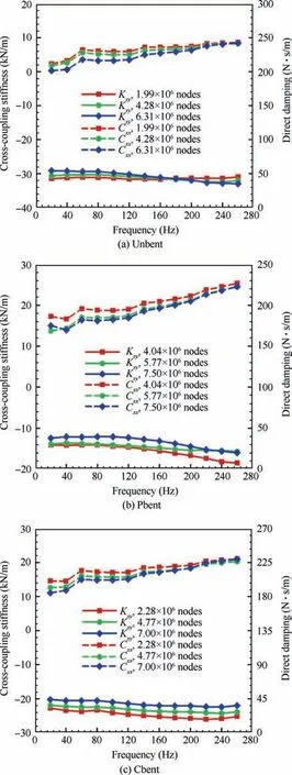
Fig. 7 Impact of mesh density on rotordynamic coefficients for three tooth bending damages.

Fig. 8 Leakage flow rate vs radial clearance.

Fig. 9 Mach number contours of three tooth bending damages.
4.4. Direct damping
The direct damping is another crucial parameter when evaluating the rotor stability of labyrinth seals. The positive direct damping will produce similar effects with the negative crosscoupling stiffness in terms of restraining the rotor forward whirl while the negative direct damping will produce similar effects with the positive cross-coupling stiffness in terms of encouraging the rotor forward whirl.

Fig. 10 Streamlines near the first tooth region showing vena contracta for three tooth bending damages.
Fig. 13 shows the dependency of direct damping versus vibration frequency at four radial clearances for labyrinth seals with three tooth bending damages. Fig. 14 gives the average gas density with various tooth clearance for three tooth bending damages.As concluded by the Refs.23,24,the direct damping is linearly increased with the increased average gas density in seal cavities when the seal geometry is fixed.For each tooth bending damage,as shown in Fig.13,an increased tooth clearance resulting in a dropped average gas density in the labyrinth seal will lead to a lower direct damping (10.4%-17.8%decrease for Unbent tooth damage, 23.9%-31.1% decrease for Pbent tooth bending damage, 18.2%-22.9% decrease for Cbent tooth bending damage with the clearance changing from 0.3 mm to 0.6 mm), that is, the relation between the direct damping and the average gas density mentioned above can be roughly applied for the same tooth bending damage with different tooth clearances. However, for different tooth bending damages with an identical tooth clearance,it always seems to be true that Pbent tooth bending damage has the lowest value in the direct damping and Unbent tooth damage has the largest one, however, as shown in Fig. 14, Pbent tooth bending damage occupies the medium average gas density and Unbent tooth damage occupies the lowest average gas density among three tooth bending damages, indicating that the relation between the direct damping and the average gas density summarized by Refs.23,24is not appropriate here as a result of large difference in the tooth shape.

Fig. 11 Direct stiffness vs whirling frequency for three tooth bending damages.
4.5. Effective damping
The effective damping was introduced to evaluate the rotor stability of labyrinth seals and illustrated in Eq. (1):


Fig. 12 Cross-coupling stiffness vs whirling frequency for three tooth bending damages.

Fig. 13 Direct damping vs whirling frequency for three tooth bending damages.
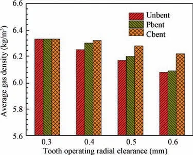
Fig. 14 Averaged gas density vs radial clearance for three tooth bending damages.
Fig. 15 shows the dependency of effective damping versus vibration frequency at four radial clearances for labyrinth seals with three different tooth bending damages. For three tooth bending damages, the positive effective damping implies that the labyrinth seal is still within a stable range. The dropped effective damping resulting from the reduced direct damping and the increasing cross-coupling stiffness is discovered with an increasing tooth clearance, and a decrease of 25.8%-49.3% for Unbent tooth damage, a decrease of 36.4%-70.1% for Pbent tooth bending damage and a decrease of 33.1%-59.8% for Cbent tooth bending damage are obtained respectively as the tooth clearance changes from 0.3 mm to 0.6 mm. Bear in mind that no inlet preswirl is imposed at the seal entrance, thus it can be inferred that the labyrinth seal with larger tooth clearance is more likely at a risk of rotor instability problem if this labyrinth seal is utilized as a shaft seal with a typical inlet preswirl ratio of 0.1-0.525in industrial applications. Compared to the Unbent tooth damage, the effective damping for Pbent tooth bending damage and Cbent tooth bending damage is lower and drops by 9.7%-33.6%and 8.5%-22.6% respectively at the tooth clearance of 0.6 mm,which suggests that Pbent tooth bending damage or Cbent tooth bending damage tends to weaken the seal stability when compared to the Unbent tooth damage.
4.6. Static pressure distribution and fluid response force
Fig. 16 shows the static pressure contours of the intermediate cavity and response forces acting on the rotor at x excitation and t=0.1 s for labyrinth seals with four radial clearances at three tooth bending damages. At x excitation, the rotor is whirling at the maximum displacement C in the positive x direction and occupies the whirling velocity tangent to the rotor motion at t=0.1 s.Noticeably,the response force F acting on the rotor is decomposed into the radial force Frand the tangential force Ft, and the tangential force at three tooth bending damages is in the opposite direction of the rotor velocity,and thus will restrain the rotor forward whirl.For Unbent tooth damage, the magnitude of the tangential force drops by 11.9%,12.6%,10.8%with an increasing clearance in 0.1 mm,and a similar drop in the magnitude of the tangential force is also discovered in the Pbent tooth bending damage and Cbent tooth bending damage. The weakened tangential force is ascribed to the movement of the position of lower and higher static pressure along the clockwise direction when the tooth clearance gradually increases, which will lower the restraint of rotor forward whirl rotor and is not beneficial to the rotor stability.Meanwhile,a close attention is paid to the difference of the tangential force among three tooth bending damages.Normalized to the Unbent tooth damage, the tangential force in the Pbent tooth bending damage and Cbent tooth bending damage is respectively 0.81 and 0.87 at the tooth clearance of 0.6 mm, disclosing that Pbent tooth bending damage or Cbent tooth bending damage weakens the rotor stability when compared to the Unbent tooth damage, which is consistent with the conclusion in Fig. 15.

Fig. 15 Effective damping vs whirling frequency for three tooth bending damages.
Fig. 17 gives the location of each cavity in the labyrinth seal. Fig. 18 shows tangential force distribution along flow direction at x excitation and t=0.1 s for labyrinth seals with three tooth bending damages at four tooth clearances. It should be pointed out that the tangential force distribution is obtained by multiplying the circumferentially integrated pressure distribution with the shaft radius as defined in Eq. (2):
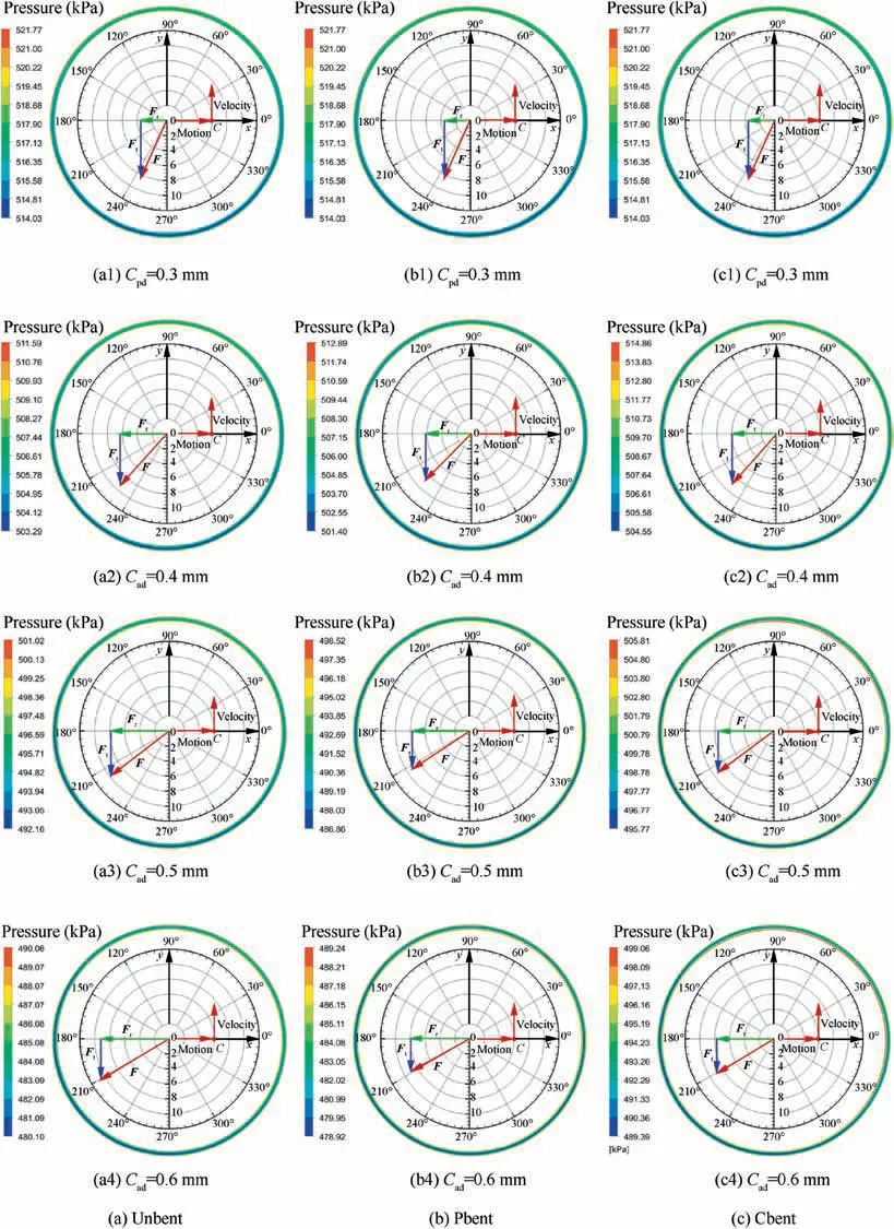
Fig.16 Static pressure contours of intermediate cavity and response forces acting on rotor for labyrinth seals with four different radial clearances at three tooth bending damages (x excitation, t=0.1 s).

where ftis the tangential force distribution along flow direction, P is the pressure on the rotor, φ is the angle of the fluid in the circumfenrential direction, R is the shaft radius.
For three tooth bending damages, an increase in the tangential force is observed when the after-damage tooth clearance increases, which is in accordance with the results of Fig. 16. Special attention is paid to the axial distribution of tangential forces for labyrinth seals with unbent tooth damage.It is clear to see that the negative tangential force gradually increases from Cavity 1 to Cavity 5,implying that the restraint of the rotor forward whirl is reduced from the Cavity 1 to Cavity 5, and thus it is possible to enhance the rotor stability by extending Cavity 1 and shortening Cavity 5.However,the similar increase in the tangential forces from upstream cavity to downstream cavity is not observed in the Pbent tooth bending damage and Cbent tooth bending damage.

Fig. 17 Locations of each cavity in labyrinth seal.

Fig.18 Calculated specific tangential force component for three tooth bending damages (x excitation, t=0.1 s).
5. Conclusions
The leakage performance and rotordynamic coefficients of labyrinth seals with three tooth bending damages were numerically investigated at four clearances,and the conclusions were showed as follows:
(1) Among three tooth bending damages,the Unbent tooth damage leaks least while the Pbent tooth bending damage leaks most,and an increase of 6.1%for Cbent tooth bending damage and an increase of 19.4% for Pbent tooth bending damage are discovered at the clearance of 0.6 mm compared to the Unbent tooth damage.
(2) For three tooth bending damages, the dropped effective damping resulting from the decreased direct damping and the increased cross-coupling stiffness is observed with an increasing tooth clearance. A decrease of 25.8%-49.3% for Unbent tooth damage, a decreased of 36.4%-70.1% for Pbent tooth bending damage and a decrease of 33.1%-59.8% for Cbent tooth bending damage are obtained respectively as the tooth clearance changes from 0.3 mm to 0.6 mm.
(3) Compared to the Unbent tooth damage, the effective damping for Pbent tooth bending damage and Cbent tooth bending damage is lower and drops by 9.7%-33.6% and 8.5%-22.6% at the tooth clearance of 0.6 mm respectively, suggesting that Pbent tooth bending damage or Cbent tooth bending damage tends to weaken the seal stability when compared to the Unbent tooth damage.
Acknowledgements
The authors thank the anonymous reviewers for their critical and constructive review of the manuscript.This study has been funded by the National Key R&D Program of China (No.2017YFB0601804)and the National Natural Science Foundation of China (No. 51776152).
杂志排行

CHINESE JOURNAL OF AERONAUTICS的其它文章
- Reliability and reliability sensitivity analysis of structure by combining adaptive linked importance sampling and Kriging reliability method
- Aeroelastic dynamic response of elastic aircraft with consideration of two-dimensional discrete gust excitation
- Thermal damage analysis of aircraft composite laminate suffered from lightning swept stroke and arc propagation
- An aerospace bracket designed by thermo-elastic topology optimization and manufactured by additive manufacturing
- Applications of structural efficiency assessment method on structural-mechanical characteristics integrated design in aero-engines
- An energy-based coupling degradation propagation model and its application to aviation actuationsystem