Effect of bristle pack position on the rotordynamic characteristics of brush-labyrinth seals at various operating conditions
2020-06-11YunqioZHANGJunLIZhigngLIXinYAN
Yunqio ZHANG, Jun LI,b,*, Zhigng LI, Xin YAN
a Institute of Turbomachinery, Xi’an Jiaotong University, Xi’an 710049, China
b Collaborative Innovation Center for Advanced Aero-Engine, Beijing 100083, China
KEYWORDS Bristle pack position;Brush-labyrinth seal;Porous medium;Rotordynamic characteristics;Whirling rotor method
Abstract Over the last few decades,the research on the effect of bristle pack position on the rotordynamic characteristics of the brush-labyrinth seals is not sufficient. To this end, two kinds of brush-labyrinth seals for the bristle pack element installed upstream of the labyrinth teeth named BSU and installed downstream of the labyrinth teeth called BSD were used to investigate the effect of bristle pack position on the rotordynamic characteristics of the brush-labyrinth seals. Using the numerical model combining the porous medium model and the whirling rotor method,the rotordynamic characteristics of the BSU and BSD at various operating conditions including four kinds of pressure ratios,five kinds of inlet preswirl speeds and four kinds of rotor spinning speeds were conducted. The obtained results show that the effects of operating conditions on rotordynamic coefficients for the different seal configurations are different. The direct stiffness, cross-coupled stiffness and direct damping of the BSU are lower than those of the BSD. The rotordynamic coefficients of the BSU are more insensitive to the operating conditions variation.From the perspective of the seal stability,the BSU is a better brush-labyrinth seal configuration at high pressure ratio,high positive preswirl or high rotor spinning speed conditions. While in the case of low pressure ratio, low positive preswirl or low rotor spinning speed conditions, the BSD is a better choice.
1. Introduction
Sealing technology is a key technology for developing high performance aero-engine.1-4As a highly efficient dynamic sealing technology,brush seals have been widely used in turbomachinery, which offer superior sealing performance and high adaptability to rotor eccentricity.5,6The labyrinth seal with a bristle pack element is called brush-labyrinth seal.It has stronger pressure bearing capacity than that of individual brush seals and its configuration is economical to retrofit the existing labyrinth seal.
The research of leakage flow characteristics is the basis for the study of brush seal performance. Schur et al.7experimentally compared the axial pressure distributions of brush seals manufactured by different methods (clamped brush seal and welded brush seal). Kang et al.8numerically studied the influence of pressure differential and geometric parameters on aerodynamic resistance of brush seals using 2-D tube banks model,which ignores the spatial variability of the bristles distribution in the bristle pack.The porous medium model which takes into account the viscous and inertial resistance of the bristles to the fluid is an effective method to investigate the flow behaviours within bristle pack.9-13
The rotordynamic coefficients of the brush seals should be considered from the perspective of system stability.5,14However, compared with the labyrinth seal, the studies for the effect of the brush seal on the rotordynamic coefficients of machines are insufficient.Conner and Childs15first experimentally studied the rotordynamic characteristics of a four-stage brush seal. The results showed the rotordynamic performance of brush seal is superior to an eight chamber labyrinth seal.Laos et al.16experimentally investigated the rotordynamic characteristics of a hybrid brush pocket damper seal and found that the damping coefficient is 2-3 times that of the original pocket damper seal when a bristle pack element is added at the outlet of the pocket damper seal. Pugachev et al.17studied the influence of the brush seal segmentation on the leakage and rotordynamic coefficients, and found that the segmentation increases direct damping coefficients.
The operating conditions have significant influence on rotordynamic coefficients of the seals, such as the pressure ratio,rotor spinning speed,and inlet preswirl.Positive preswirl will weaken the rotor system stability while negative preswirl will stabilize the rotor.18,19The bristle pack elements of brush-labyrinth seals can be installed upstream or downstream of labyrinth teeth,leading to different tangential airflow speeds of flow passage. The bristle pack produces flow resistance to the fluid flowing through it,so on the one hand,it will decrease positive tangential airflow speed of flow passage; and on the other hand,reduce the entrance negative preswirl velocity generated by other parts18if the bristle pack is installed upstream of labyrinth teeth.As a result,the effects of bristle pack installation position on the rotordynamic performance at various operating conditions are different.
The aim of the this paper is to study the effect of bristle pack installation position on the rotordynamic characteristics of brush-labyrinth seal at various operation conditions and provide a reference for brush-labyrinth seal design at different operating conditions.The numerical model combining the porous medium model and the whirling rotor method is applied to investigate rotordynamic characteristics of the brush-labyrinth seal.
2. Computational model and numerical approach
2.1. Physical model
The detailed geometrical parameters of two brush-labyrinth seals can be found in Fig. 1 and Table 1, which were derived from the experimental data.20,21The first brush-labyrinth seal is named as BSU with a bristle pack element upstream of six labyrinth teeth,and the second type is BSD with a bristle pack element downstream of six labyrinth teeth.

Fig. 1 Cross-sectional configuration and parameters of brushlabyrinth seals.

Table 1 Geometry and operating parameters of brushlabyrinth seal.
2.2. Computational mesh
The multi-block structural mesh was built utilizing ANSYS ICEM CFD software, and the grids were refined in the nearwall and the bristle pack region. The computational mesh of the BSU was shown in Fig. 2. To exclude the influence of the computational mesh on the obtained results,three different meshes were generated and calculated for two types seals.The three different grid nodes are 4.94 million, 7.87 million and 12.20 million.
2.3. Numerical approach
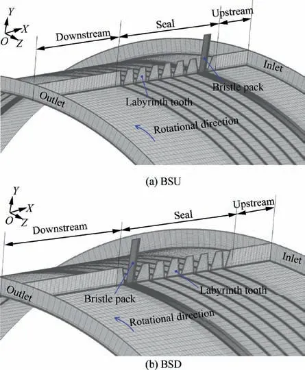
Fig. 2 Computational mesh of BSU and BSD.
As shown in Fig.3(a),the rotor spins around the center of the rotor with a spinning speed ω and whirls around the center of the stator with a whirling speed Ω along a circular orbit. The internal flow field of the rotating seal is unsteady and the transient analysis method is needed to solve the internal flow field at the stationary frame. A three-dimensional steady numerical model can be used to convert the unsteady problem in the stationary frame into a steady problem in a reference frame rotating with a whirling frequency -Ω. The rotor spins around the center of the rotor at the eccentric position and the stator spins around the stator center,as shown in Fig.3(b).At present,the‘‘3D steady-state” CFD numerical model, or called whirling rotor method, has been used by many researchers to investigate the rotordynamic characteristics of labyrinth seals22,23and brush-labyrinth seals.17,24
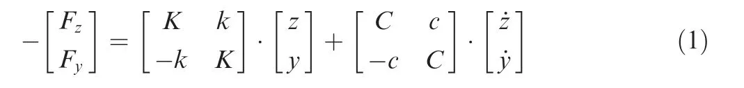
where K and k are direct stiffness and cross-coupled stiffness,respectively; C and c represent direct damping and crosscoupled damping,respectively.The radial force Frand tangential force Ftcan be used to measure the fluid excitation force,when supposing the rotor circumferentially whirling around the stator center,the rotor eccentricity is e and the whirling frequency is Ω.
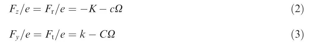
According to Eqs. (2) and (3), calculation of stiffness and damping coefficients needs the value of radial and tangential forces exerted by the seal at different whirl frequencies Ω,and these forces can be obtained directly from ANSYS CFX. At least two data sets at different whirl frequencies Ω are required to calculate the rotordynamic coefficients. In this paper,these coefficients were calculated by obtaining the reaction forces at three whirl frequencies Ω including-176.5 rad/s,0 rad/s and 176.5 rad/s.The direct stiffness K is mainly related to the critical speed of the rotor system and the positive direct stiffness K will increase the critical speed of the rotor system.The rotor system stability is degraded when the cross stiffness k is positive. The positive value of direct damping C indicates that it can restrain the rotor instability, while the negative value of direct damping C can induce the rotor instability.
As shown in Eq. (4), the porous medium model is used to study the flow behaviors within bristle pack in this work,which means that the resistance of the bristle to the fluid Fbiis added to the momentum equation as a source term in the bristle pack region. More information about the porous medium model can be found in the previous work.11As shown in Fig.4,the actual bristle pack thickness and bristle pack radial clearance decrease with the increasing pressure difference.The calibration of these two parameters can be found in Ref.21.where ρ is density of fluid, u means fluid velocity, i and j are spatial coordinate directions, p is static pressure, and σ represents Reynolds stress.
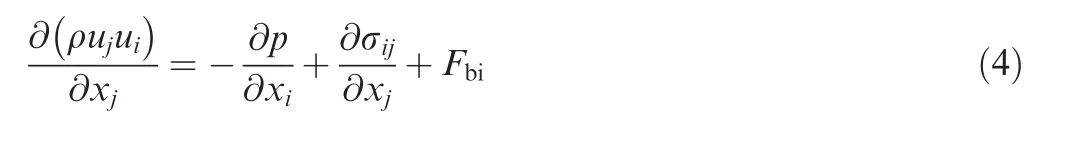
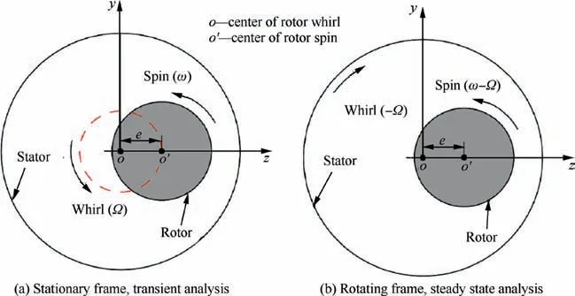
Fig. 3 ‘‘Whirling rotor method” for seal rotordynamic coefficients calculation.

Fig.4 Bristle pack thickness and bristle pack radial clearance vs pressure ratio.
2.4. Boundary conditions
As listed in Table 2, the total pressure and total temperature boundary condition were set at the inlet. Besides, the flow direction was given at the inlet.The positive inlet preswirl indicates that preswirl direction is the same as the spinning direction of the rotor. The negative inlet preswirl indicates that the preswirl direction and the rotor spinning direction are opposite. The static pressure was set up at the outlet boundary.The working fluid is ideal air.The rotor surface,stator surface and fluid domain rotational speed were set according to the foregoing whirling rotor method. All solid wall surfaces were applied as non-slip and adiabatic conditions. The CFD model was established in ANSYS CFX software and SST (Shear Stress Transport) turbulence model was used.24,29
2.5. Numerical approach validation
The numerical approach is validated by computing the rotordynamic coefficients of a similar brush-labyrinth seal. The precdited rotordynamic coefficients of a brush-labyrinth seal as function of pressure ratio are plotted in Fig. 5. The present numerical direct stiffness and cross-coupled stiffness are in good agreement with numerical results30over the whole pressure range.The reliability of the numerical method for prediction of the brush-labyrinth seal rotordynamic coefficients is validated as a whole.
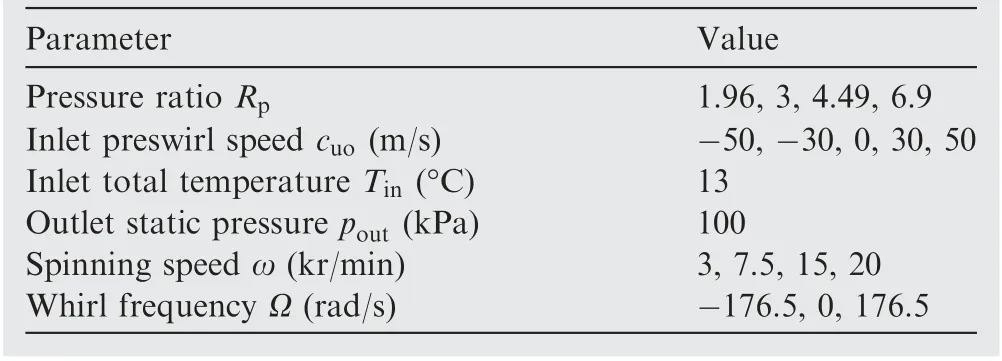
Table 2 Operating conditions of brush-labyrinth seals.
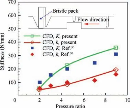
Fig. 5 Predicted rotordynamic coefficients of a brush-labyrinth seal as function of pressure ratio.
3. Results and discussions
The effect of the bristle pack installation position on the rotordynamic characteristics of brush-labyrinth seals at various operation conditions was investigated in detail using the established CFD model of the brush-labyrinth seal.
3.1. Influence of pressure ratio on rotordynamic coefficients
Fig. 6 illustrates rotordynamic coefficients of the two types of seals at different pressure ratios for three different meshes.The rotordynamic coefficients of two types of brush-labyrinth seals are slightly changed when the grid number increases.The computational results of 7.87 million nodes case and those of 12.20 million nodes case are almost the same. Therefore, as a result of the trade-off between accuracy and computational time,7.87 million nodes for two seals were chosen to be the final nodes in this work. Figs. 6(a) and (b) plot the direct stiffness coefficients and cross-coupled stiffness coefficients of the two types of seals versus pressure ratio, respectively. The stiffness coefficients of two seals increase with an increasing pressure ratio, and the stiffness coefficients of the BSD is higher than that of the BSU. Compared with the BSD, the stiffness coefficients of the BSU are less sensitive to the variation of pressure ratio. Damping coefficients of the BSU and the BSD can be observed from Figs. 6(c) and (d), respectively. The damping coefficients of the BSD increase with respect to the increasing of pressure ratio, while the damping coefficients of the BSU change little with the pressure ratio variation. Furthermore,the direct damping coefficient of the BSD is higher than that of the BSU. As shown in Eq. (5), the effective damping Ceffis an indicator used to evaluate the sealing stability.31

where ωnrepresents natural frequency of rotor system. The natural frequency of rotor system is based on rotor system parameters, such as bearing span distance and mass of rotor.The brush seal parameters in this paper were derived from Ref.21and it is tested on the seal test rig.24In order to evaluate the seal stability, 28 Hz was set to the natural frequency of rotor system in this paper.This value is nearly coincident with the setting in the Ref.24. Fig. 6(e) plots the effective damping at different pressure ratios.The effective damping of two seals decreases with the increase of pressure ratio. The effective damping of the BSD is higher than that of the BSU at the low pressure ratio condition, while the effective damping of the BSU is higher than that of the BSD at high pressure ratio condition.
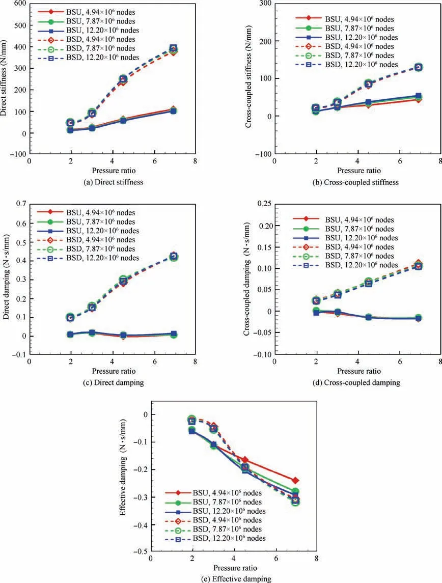
Fig. 6 Impact of mesh density on rotordynamic coefficients at different pressure ratios (ω=1.5 kr/min, cu0 =30 m/s).
In order to explain the influence mechanism of the pressure ratio on the the rotordynamic characteristics of seals,it is necessary to show the circumferential pressure distribution in the flow passage at different pressure ratios.As illustrated in Fig.7(a), the three pressure point positions of the BSD in the axial direction are located at 0.15 mm away from the rotor surface in the middle of the first seal cavity, the fourth seal cavity and the bristle pack. The three pressure point positions of the BSU in the axial direction are situated at 0.15 mm away from the rotor surface in the middle of the bristle pack, the third seal cavity and the sixth seal cavity. The Position 3 of the BSD and Position 1 of the BSU represent brush seal region,and other two positions stand for labyrinth seal region.The differential pressure Δpφ,Δpα,β,Δpφ,τalong circumference direction are defined as follows.
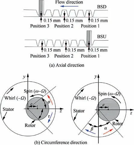
Fig. 7 Schematic diagram of pressure point position.

where p is static pressure;φ,α,β and τ are shown in Fig.7(b);m represents axial position number; and pmin,mmeans minimum circumferential pressure value at each axial position.
As shown in Figs. 8(a) and (b), the increase of pressure ratio significantly affects the circumferential pressure distribution of the flow passage, especially for the bristle pack region,which affects the rotordynamic coefficients of seals. It should be noted that the radial force Frand tangential force Ftsatisfy the Eqs.(7)and(8),respectively,so Δpα,βand Δpφ,τat different axial positions can be used to evaluate rotordynamic coefficients.

where x is axial direction and L means seal axial length.
As illustrated in Figs.8(c)and(d),with the increasing pressure ratio Rp, the pressure differences Δpα,βof labyrinth seal region decrease slightly, while the pressure difference Δpα,βat brush seal region increases significantly at the same whirl frequency Ω.So the pressure difference Δpα,βincreases as a whole.Also, most of the pressure differences Δpα,βare offered by brush seal sections and the pressure difference Δpα,βof the brush seal sections (Position 3) of the BSD are higher than those of the brush seal section(Position 1)of the BSU.Besides,the pressure differences Δpα,βof labyrinth seal sections (Position 1 and Position 2) of the BSD are higher than those of the labyrinth seal sections (Position 2 and Position 3) of the BSU. So the pressure differences Δpα,βof the BSD are higher than those of the BSU at the same working conditions.According to the above reasons,the direct stiffness coefficients of seals increases as a whole due to the increase of pressure ratio and the direct stiffness of the BSD is higher than that of the BSU. Besides, from the point of view of whole BSD,the pressure difference Δpα,βof the condition with pressure ratio 6.9 increases more obviously with the increasing whirl frequency compared with the condition of pressure ratio equal to 3, so the cross-damping c of the BSD increases with the increase of pressure ratio. The pressure difference Δpα,βof the BSD changes little as the whirl frequency increases at both pressure ratio conditions, which is the reason why the crossdamping c of the BSU is smaller than that of the BSD and is insensitive to the change of pressure ratio.
As plotted in Figs. 8(e) and (f), the pressure differences Δpφ,τincrease as the pressure ratio Rpincreases as a whole.Moreover, most of the pressure differences Δpφ,τare offered by brush seal sections and the pressure differences Δpφ,τof the brush seal section (Position 3) of the BSD are higher than those of the brush seal section(Position 1)of the BSU.Besides,the pressure differences Δpφ,τof labyrinth seal sections (Position 1 and Position 2) of the BSD are higher than those of the labyrinth seal sections (Position 2 and Position 3) of the BSU. So the pressure differences Δpφ,τof the BSD are higher than those of the BSU at the same working conditions. Based on these two factors,the phenomenon that cross-coupled stiffness k of seals increase as a whole due to the increase of pressure ratio and the phenomenon that the cross-coupled stiffness of the BSD is higher than that of the BSU are observed.Besides, the reason why the direct damping C of the BSD increases with the increase of pressure ratio is that the pressure differences Δpφ,τof the condition with pressure ratio 6.9 decrease more obviously with the increasing whirl frequency compared with the condition of pressure ratio equal to 3.For the BSU, the pressure difference Δpφ,τat the condition with pressure ratio 6.9 at brush seal region decreases slightly more obviously with the increase of whirl frequency compared with the condition of pressure ratio equal to 3,while the opposite is true at the labyrinth seal region.So the direct damping C of the BSU changes little with the pressure ratio variation and lower than that of the BSD.
3.2. Influence of inlet preswirl on rotordynamic coefficients
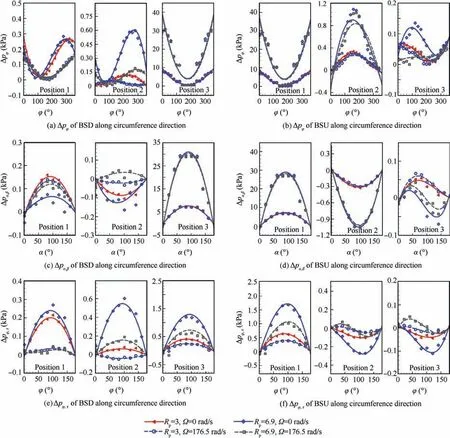
Fig. 8 Pressure differences along circumference direction at different pressure ratios (ω=1.5 kr/min, cu0 =30 m/s).
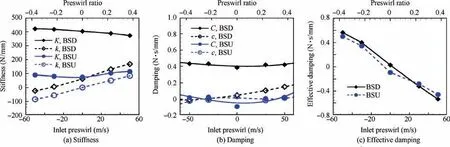
Fig. 9 Rotordynamic coefficients as a function of inlet preswirl (Rp=6.9, ω=1.5 kr/min).
Fig.9 shows the relationship between the rotordynamic coefficients and the inlet preswirl (or preswirl ratio). The preswirl ratio μ0is defined as the ratio of the inlet preswirl speed to the rotor surface speed. It can be seen from Fig. 9(a) that the direct stiffness of the BSD slightly decreases with the increase of inlet preswirl and the direct stiffness of the BSU changes little with the inlet preswirl variation.The cross-coupled stiffness coefficients of both seals linearly increase with the increase of inlet preswirl. Compared with the BSU, the stiffness coefficients of the BSD are higher. As we can see from Fig. 9(b),the effects of the inlet preswirl on the direct damping of the two seals are similar. Direct damping coefficients are insensitive to the inlet preswirl variation, and the direct damping of the BSD is larger than that of the BSU. The cross-coupled damping of the BSD increase with an increase of inlet preswirl.The cross-coupled damping of the BSU fluctuates with the change of inlet preswirl but the variation on the whole is small.Fig. 9(c) shows the effective damping of the BSU and BSD.The effective damping decreases with the increase of inlet preswirl for both seals. The negative inlet preswirl will significantly improve the effective damping of seals, thus improving the rotor system stability. The effective damping of the BSD is higher than that of the BSU at negative inlet preswirl or low positive inlet preswirl,while the effective damping of the BSU is higher than that of the BSD at high positive inlet preswirl condition. Because of the resistance of the bristles to the flow, the bristle pack acts as a ‘‘swirl brake” which would decrease the positive or negative tangential airflow speed in the seal flow passage,so the effective damping of the BSU is insensitive to the inlet preswirl speed variation, compared with the BSD.It means that the BSU will decrease the benefit for rotor system stability caused by negative inlet preswirl condition and the disadvantage for rotor system stability caused by positive inlet preswirl condition.
Similar to the analyses in Section 3.1, Fig. 10 shows the pressure differences along the circumference at different inlet preswirl speeds. As illustrated in Figs. 10(a) and (b), the pressure differences Δpφalong circumference direction are changed by the increasing inlet preswirl speed cu0, which has an significant influence on the rotordynamic coefficients of seals.
As shown in Figs. 10(c) and (d), the pressure differences Δpα,βof the BSD decrease with the increase of the inlet preswirl speed,and those value of the BSU change little as the inlet preswirl speed increases due to the ‘‘swirl brake” effect of bristle pack. So the direct stiffness K of the BSD decreases due to the increase of the inlet preswirl speed and the direct stiffness of the BSU is insensitive to the increasing inlet preswirl speed.Also,the higher inlet preswirl speed,the higher increase in pressure difference Δpα,βof the BSD with the increasing whirl frequency condition. So the cross-coupled damping c of the BSD increases with the increase of the inlet preswirl speed.The cross-coupled damping c of the BSU changes little with the increasing inlet preswirl speed because of the approximately equal increase of pressure difference Δpα,βwith the increasing whirl frequency as a whole at different inlet preswirl speeds.
As the inlet preswirl speed increases, the pressure differences Δpφ,τof the BSD significantly increase at each position while the increase of those values of the BSU only occurs at the brush seal region, as shown in Figs. 10(e) and (f). Besides,the increase of pressure difference Δpφ,τof two seals changes little as the whirl frequency increases at both inlet preswirl conditions.According to the above two reasons,the cross-coupled stiffness k increases and the cross-damping c changes little when the inlet preswirl increases.
3.3. Influence of rotor spinning speed on rotordynamic coefficients
Figs. 11 and 12 show the rotordynamic coefficients of two brush-labyrinth seals versus rotor spinning speed (or preswirl ratio) at the 30 m/s inlet preswirl condition and -30 m/s inlet preswirl condition, respectively. As illustrated in Figs. 11(a)and 12(a), the stiffness coefficients of the BSD increase with the increase of rotor spinning speed and the stiffness coefficients of the BSU are insensitive to variation of rotor spinning speed.As shown in Fig.11(b),the rotor spinning speed has little effect on direct damping of the BSD and the increasing rotor spinning speed would slightly decrease the direct damping of the BSU at the 30 m/s inlet preswirl condition. The cross-coupled damping coefficients of both seals increase with the increasing rotor spinning speed at the 30 m/s inlet preswirl condition. As illustrated in Fig. 12(b), the tendency at the-30 m/s inlet preswirl condition is different. On the whole,the damping coefficients of the BSD increase with an increasing rotor spinning speed, while direct damping of the BSU is insensitive to the rotor spinning speed variation and the cross-coupled damping would slightly decrease due to the increasing rotor spinning speed. As plotted in Figs. 11(c) and 12(c),the effective damping decreases with an increasing rotor spinning speed. Compared with the BSU, the effective damping of the BSD is more sensitive to rotor spinning speed,especially at the negative inlet preswirl condition. The effective damping of the BSD is higher than that of the BSU at high rotor spinning speed condition, while in the case of low rotor spinning speed conditions, the opposite is true.
Fig. 13 plots the pressure differences along the circumference at two rotor spinning speeds, which is similar to the descriptions in Section 3.1. Figs. 13(a) and (b) show pressure differences Δpφalong circumference direction of two seals at two rotor spinning speeds.The circumferential pressure distribution of the flow passage is significantly affected by the change of rotor spinning speed ω, so the rotordynamic coefficients of seals will be changed with the increasing rotor spinning speed ω.
As shown in Figs.13(c)-(f),when the rotor spining speed ω increases, the pressure differences Δpα,βand Δpφ,τof the BSD significantly increase as a whole although those values slightly decreases at the labyrinth seal region. While the pressure differences Δpα,βand Δpφ,τat brush seal region of the BSU increase slightly and these values at the labyrinth seal region of the BSU decrease, so the pressure differences Δpα,βand Δpφ,τof the BSU change little with the increasing rotor spining speed ω as a whole.According to the above analyses,the direct stiffness K and cross-coupled stiffness k of the BSD increase as a whole due to the increase of the rotor spining speed and these two stiffness coefficients of the BSU are insensitive to variation of the rotor spinning speed. Besides, the higher rotor spinning speed, the more increase of pressure difference Δpα,βwith the increasing whirl frequency as a whole, so the cross-coupled damping c of two seals increases with the increase of rotor spinning speed. The decrease in pressure difference Δpφ,τof the BSD with the increasing whirl frequency is approximately equal at different rotor spinning speeds,so the direct damping C of the BSD changes little with the increasing rotor spinning speed. For the BSU, the pressure difference Δpφ,τat the high rotor spinning speed condition at brush seal region decreases slightly with the increase of whirl frequency when compared with the lower rotor spinning speed condition. While pressure differences Δpφ,τincrease more obviously with the increase of whirl frequency and the increase of rotor spinning speed at the labyrinth seal region. So the direct damping C of the BSU changes little with the pressure ratio variation as a whole.
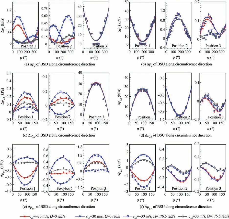
Fig. 10 Pressure differences along circumference direction at different inlet preswirl speeds (Rp =6.9, ω=1.5 kr/min).

Fig. 11 Rotordynamic coefficients vs rotor spinning speed at positive preswirl condition (Rp =6.9, cu0 =30 m/s).

Fig. 12 Rotordynamic coefficients vs rotor spinning speed at negative preswirl condition (Rp =6.9, cu0 =-30 m/s).
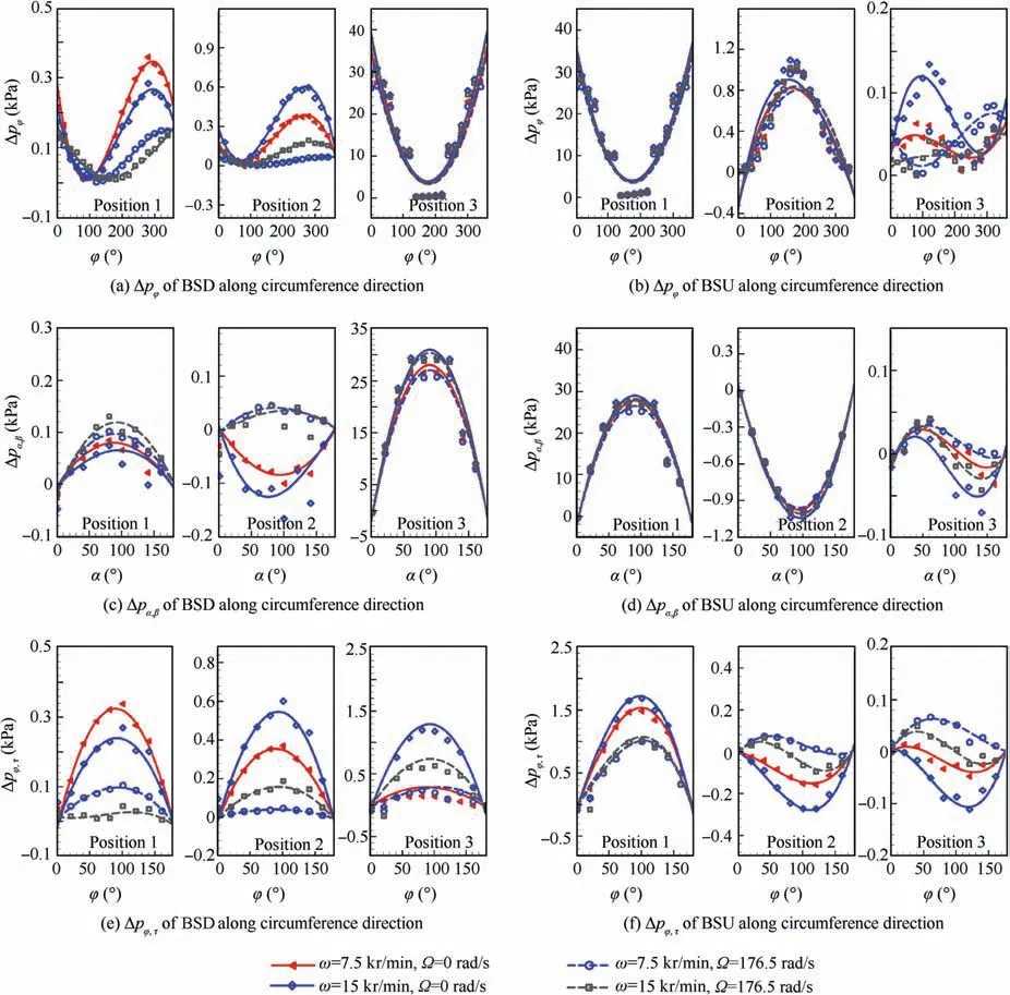
Fig. 13 Pressure differences along circumference direction at different rotor spinning speeds (Rp =6.9, cu0 =30 m/s).
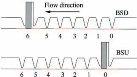
Fig. 14 Schematic diagram of seal section position.

Fig. 15 Direct stiffness along axial direction at various operation conditions.
3.4. Rotordynamic coefficients of seal section along flow direction
To investigate the effect of the bristle pack installation position on the rotordynamic characteristics of brush-labyrinth seals better, the rotordynamic characteristics of each seal section along flow direction are required. Fig. 14 plots the schematic diagram of the seal section position. Section 6 of the BSD and Section 0 of the BSU are brush seal sections. Sections 0-5 of the BSD and Sections 1-6 of the BSU are labyrinth seal sections.Fig.15 shows variation of the direct stiffness of seven seal sections at the different working conditions. Direct stiffness of the labyrinth seal sections of the BSD is near zero and over 92%of positive direct stiffness is offered by the brush seal section.The direct stiffness of the BSU’s labyrinth seal sections is negative and increases along the flow direction and brush seal section of BSU provides nearly 100% of positive direct stiffness.The inlet preswirl variation and rotor spinning speed variation primarily affect the direct stiffness of brush seal section.
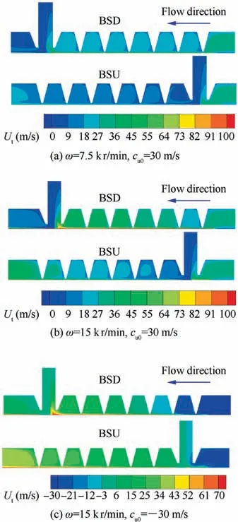
Fig. 16 Tangential airflow speed contours of brush-labyrinth seals at different working conditions (Rp =6.9).
The tangential airflow speed Utof flow passage increases with the increasing rotational speed and inlet preswirl speed,which would affect the rotordynamic characteristics of seals,especially for effective damping. In order to investigate the effect of rotational speed and inlet preswirl speed on rotordynamic characteristics of seal sections, the tangential airflow speed of flow passage was studied at first. Fig. 16 shows the tangential airflow speed contours of the brush-labyrinth seals at different working conditions. The tangential airflow speed Utof the flow passage of labyrinth seal section will increase along the flow direction due to rotor spinning, especially for the region near to the rotor surface. The comparison between Figs. 16(a) and (b) shows that the tangential speed in the flow passage increases with the increase of the rotor spinning speed.The bristle pack acts as a ‘‘swirl brake” caused by the resistance of the bristles to the flow, as shown in Eq. (4), which would decrease the positive or negative tangential airflow speed in the seal flow passage, as plotted in Figs. 16(a)-(c).
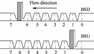
Fig. 17 Schematic diagram of position of flow passage section.
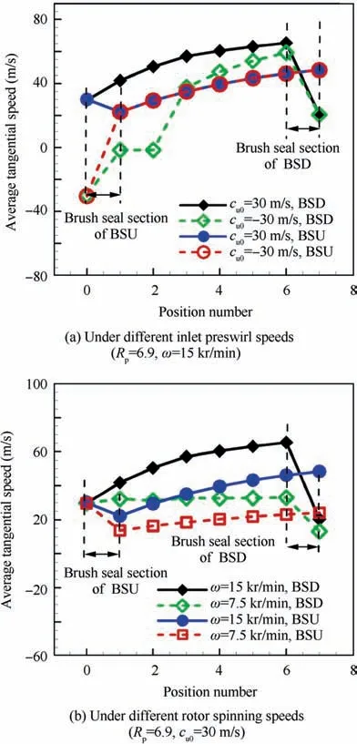
Fig. 18 Average tangitial speed of flow passage section at different working conditions.

Fig. 19 Effective damping along axial direction at various operation conditions.

Table 3 Summary of effects of operating conditions on rotordynamic characteristics.
To show the influence of bristle pack position on the tangential airflow speed Utas a whole,the circumferential average tangential airflow speeds U-tof different flow passage sections(as shown in Fig.17) at different working conditions are plotted in Fig. 18. For the positive inlet preswirl condition (preswirl ratio μ0=0.225), the average tangential airflow speed U-tof the BSD increases along the flow direction and decreases rapidly after passing through the bristle pack.The average tangential airflow speed U-tof the BSU decreases after passing through the bristle pack and then increases along the flow direction for the positive inlet preswirl condition. As to the negative inlet preswirl condition (preswirl ratio μ0=-0.225),the average tangential airflow speed U-tof the BSD increases gradually from negative speed to positive speed along the flow direction,then decreases after passing through the bristle pack,while the average tangential airflow speed U-tof the BSU changes rapidly from negative value to positive value after passing through the bristle pack and increases gradually along the axial direction in accordance with the positive inlet preswirl condition.In addition,the average tangential airflow speed U-tof labyrinth sections of the BSD is higher than that of the BSU at the positive inlet preswirl condition. However, at the negative inlet preswirl condition, the average tangential airflow speed U-tof labyrinth sections of the BSU is higher than that of the BSD at first along the flow direction,and then less than that of the BSD. As can be seen from Fig. 18(b), the average tangential speed U-tof the BSD almost keeps at a constant level along the axial direction and decreases rapidly after passing through the bristle pack when the rotor spinning speed is low (preswirl ratio μ0=0.449), while the average tangential speed U-tof the BSU decreases rapidly after the bristle pack and then increases along the flow direction.
Fig. 19(a) shows effective damping along axial direction at various operation conditions. The inlet preswirl and bristle pack position have significant effects on the effective damping of seal sections.The effective damping of labyrinth seal section of the BSU is near to zero. The negative inlet preswirl would increase the effective damping of brush seal section, while has little influence on effective damping of labyrinth seal section. The reason is that bristle pack installed at the inlet position of the seal will act as a‘‘swirl brake”(as plotted in Figs.16 and 18) which decreases the negative and positive inlet preswirl,and the effect of the inlet preswirl variation on the effective damping of BSU is limited at the brush seal section. For the BSD, the negative inlet preswirl would significantly increase the effective damping of seal sections, especially the brush seal section.
The effective damping versus rotor spinning speed is shown in Fig. 19(b). For both types of seals, the effect of rotor spinning speed variation on the effective damping of labyrinth seal sections far away from the brush seal section is limited. As to the BSD,the effective damping of brush seal section and labyrinth seal sections near to the bristle pack would significantly decrease with the increasing rotor spinning speed. For the BSU, the increasing of rotor spinning speed would slightly decrease the effective damping of the brush seal section and labyrinth seal sections near to the bristle pack. The following point is explained for the phenomenon in Fig. 19(b). As illustrated in Fig. 18(b), the increase amplitude of the tangential airflow speed of the BSU in the brush seal section and the labyrinth seal sections near to the bristle pack is smaller than that of the BSD when the rotor spinning speed increases, so the influence of the increasing rotor spinning speed on the effective damping coefficients of the BSD in the brush seal section and the labyrinth seal sections near to the bristle pack is higher than that of the BSU.
To more intuitively compare the rotordynamic characteristics of both the seals at various operation conditions, a summary of the effects of operating conditions on rotordynamic characteristics is shown in Table 3. The symbols ‘‘↑”, ‘‘↓”and ‘‘~” represent ‘‘increase”, ‘‘decrease” and ‘‘change little”,respectively.
4. Conclusions
The effect of the bristle pack installation position on the rotordynamic characteristics of the brush-labyrinth seals at various operating conditions was investigated using numerical simulations in this work.
(1) Compared with the BSD, the direct stiffness, crosscoupled stiffness and direct damping of the BSU are lower at the same operating conditions and rotordynamic coefficients of the BSU are more insensitive to operating conditions variation. Direct stiffness coefficients of the BSD increase with the increase of the pressure ratio and rotor spinning speed, while decrease due to the increasing inlet preswirl. Direct stiffness coefficients of BSU increase with the increasing pressure ratio and are insensitive to the inlet preswirl variation and rotor spinning speed variation.
(2) The effective damping of the BSD and the BSU decrease with the increasing pressure ratio, inlet preswirl and rotor spinning speed. Compared with the BSU, the effect of rotor spinning speed on the effective damping of the BSD is significantly higher.
(3) Before the brush-labyrinth seal design or the existing labyrinth seal retrofit, the pressure ratio and the inlet preswirl should be estimated first. From the perspective of brush-labyrinth seal stability, the BSU is a better brush-labyrinth seal configuration at the high pressure ratio,high positive preswirl or high rotor spinning speed conditions because of its higher effective damping.While in the case of low pressure ratio,low positive preswirl or low rotor spinning speed conditions,the BSD is a better choice.
(4) The bristle pack acts as a ‘‘swirl brake” which would decrease the tangential airflow speed in the seal flow passage.
(5) Over 92% of positive direct stiffness of the BSD and nearly 100% of positive direct stiffness of the BSU are offered by brush seal element. The direct stiffness of the labyrinth seal sections of the BSD is near zero and this value of the BSU is negative. The effect of inlet preswirl variation on effective damping is concentrated in the brush seal section of the BSU and the all seal sections of the BSD. The rotor spinning speed variation mainly affects the effective damping of the brush seal section and labyrinth seal sections near to the brush seal section.
(6) The numerical model combining the porous medium model and the whirling rotor method is capable of predicting rotordynamic characteristics of the brushlabyrinth seals.However,comparisons between rotordynamic characteristics of brush-labyrinth combined seal with only one bristle pack and those of multi-stage brush seal should be studied further.
Acknowledgements
The authors thank the anonymous reviewers for their critical and constructive review of the manuscript. This study was co-supported by the National Key R&D Program of China(No. 2017YFB0601804) and the National Natural Science Foundation of China (No. 51776152).
杂志排行

CHINESE JOURNAL OF AERONAUTICS的其它文章
- Reliability and reliability sensitivity analysis of structure by combining adaptive linked importance sampling and Kriging reliability method
- Aeroelastic dynamic response of elastic aircraft with consideration of two-dimensional discrete gust excitation
- Thermal damage analysis of aircraft composite laminate suffered from lightning swept stroke and arc propagation
- An aerospace bracket designed by thermo-elastic topology optimization and manufactured by additive manufacturing
- Applications of structural efficiency assessment method on structural-mechanical characteristics integrated design in aero-engines
- An energy-based coupling degradation propagation model and its application to aviation actuationsystem