Effect of Ca addition on the microstructure and the mechanical properties of asymmetric double-sided friction stir welded AZ61 magnesium alloy
2020-04-29MengranZhouYoshiakiMorisadaHidetoshiFujii
Mengran Zhou, Yoshiaki Morisada, Hidetoshi Fujii
Joining and Welding Research Institute (JWRI), Osaka University, Japan
Abstract The effects of 2% Ca addition on the microstructure and the mechanical properties of the asymmetric double-sided friction stir welded magnesium alloy AZ61 were investigated. Compared to the Ca-free AZ61magnesium alloy, the addition of 2% Ca significantly refines the grains in the stir zone after welding. Due to the existence of thermally stable Al2Ca particles, there is no noticeable change in the grain size in the stir zone regardless of the welding heat input. The electron backscattered diffraction analysis at the center of the stir zone confirmed the significant deterioration of the (0001) texture strength from the addition of 2% Ca. The tensile test of the joint suggested that the addition of 2% Ca provides stable tensile properties to the joint regardless of the welding parameters. The critical (0001) texture strength that determines the ultimate tensile strength decreased from 20 to 15 by the Ca addition. The addition of Ca enhanced the deterioration of the plastic elongation when the (0001) texture strength increased.
Keywords: Mg alloy; Friction stir welding; Microstructure; Mechanical properties; Texture.
1. Introduction
With the ongoing energy crisis, reducing carbon emissions and developing sustainable resources has become a worldwide consensus. The introduction of lightweight strategies into the manufacturing of vehicles, including cars, high-speed trains,airplanes, and aerospace equipment, is considered a practical approach [1–3]. Magnesium (Mg) alloy can be used as a structural material to reduce the weight of vehicles due to several attractive properties, such as its high specific strength,high specific toughness, and excellent vibration absorption capacity. These favorable properties make Mg alloy highly attractive to replace steel and aluminum alloys in the manufacturing of the next-generation high-speed vehicles [1,2,4].However, the industrial application of the Mg alloys is hindered by the highly-active chemical properties and the relatively low ignition temperature that exist in conventional Mg alloys like the AZ, AM, and ZK series [1,2]. Recently, the addition of calcium (Ca) into conventional Mg alloys simultaneously allowed optimal mechanical properties and an increased ignition temperature[5–11].At high temperatures,the addition of Ca modifies the oxidization process by forming a dense oxidation layer on the surface of the molten metal that prevents the inward diffusion of oxygen. Therefore, Ca-added magnesium alloys are called non-combustive Mg alloys [11].
To expand the industrial application of non-combustive Mg alloys, an energy effective and environmentally friendly welding method is needed. However, obtaining a sound Mg alloy joint with excellent mechanical properties by fusion welding is quite difficult due to the formation of pores and cracks [12–15]. Moreover, argon gas is needed during welding to prevent ignition. To overcome these problems, friction stir welding (FSW) can be used to weld Mg and its alloys[16]. Conventional FSW is achieved by a rotating tool with a cylindrical or truncated-cone probe and utilizing the heat generated by friction and the plastic deformation to soften the material while moving in a specific direction to achieve the welding. Conventional FSW has been successfully used forseveral types of Mg alloys [17–22]. The joints obtained by conventional FSW show a superior tensile strength compared to those formed by fusion welding. However, a decreased ductility of the joint along the transverse direction (TD) has been widely reported [17–19,22]. Intensive studies revealed that the decreased ductility of the joint along the TD originates from the highly concentrated (0001) texture formed in the stir zone (SZ) [23–25]. The simple shearing deformation introduced by the stirring causes a highly concentrated (0001)texture in the SZ. Due to the hexagonal closed-pack (HCP)structure, the basal ({0001}<11–20>) slip most likely occurs during the FSW of the Mg alloys [23,24]. Combined with the simple material flow during conventional FSW, a highly concentrated (0001) texture is formed in the SZ by the activation of basal slip during welding.

Table 1 Chemical compositions and mechanical properties of the materials used.
A new welding method, namely asymmetric double-sided friction stir welding (DFSW), uses two separate tools for stirring from both the upper and lower sides during the welding of Mg alloys [26–28]. A much more complicated material flow is obtained during welding because of the asymmetrical layout of the upper and the lower tools. Therefore, a randomized crystal orientation is observed in the SZ of an Mg alloy joint formed by DFSW. At the same time, excellent tensile properties (strength and ductility) are obtained along the TD.Therefore, asymmetric DFSW is an ideal welding method for Mg alloys. Several studies achieved the texture randomization of an AZ31 Mg alloy using DFSW [26,27]. The successful uses of asymmetric DFSW to Ca-added Mg alloys were also reported [28,29]. However, the effects of the Ca addition on the microstructure and the mechanical properties of the Mg alloy joint formed by the asymmetric DFSW have not been fully investigated.
In this study, the effects of the addition of 2% Ca on the intermetallic compound formation and distribution, the microstructure, the texture, and the mechanical properties of the joint are discussed.
2. Materials and methods
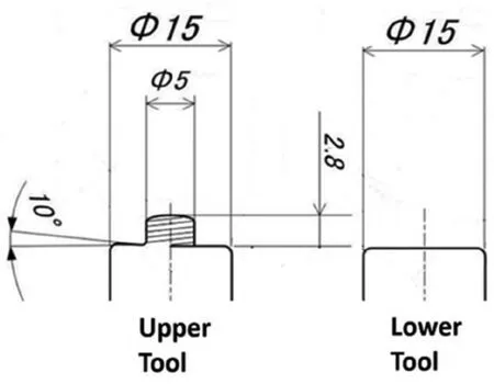
Fig. 1. Schematic illustration of the upper and lower tools.
Extruded AZ61 (Mg-6% Al-1% Zn) and AZX612 (Mg-6%Al-1% Zn −2% Ca) Mg alloy plates were prepared. Both the AZ61 and AZX612 plates were extruded at 350°C with the extrusion speed of 1m/min. After extrusion, the plates were conducted with 2 h of heat-treatment at 250°C under the Argon protection.The chemical composition and the mechanical properties are summarized in Table 1. The plates were prepared in 65-mm wide, 200-mm long, and 3-mm thick samples using a linear motor driven wire-cut electrical discharge machine (EDM, Sodick AG360L). The oxide layer on the surface was carefully removed before welding using 2000#SiC abrasive paper and cleaning with high purity ethanol.An upper tool with a threaded probe and a flat lower tool(Fig. 1) enabled the asymmetric DFSW. The upper tool had a shoulder diameter of 15mm. The probe had a diameter of 5mm and a length of 2.8mm. The lower tool is a flat tool with a shoulder diameter of 15mm without the probe. Both tools were made of JIS-SKD61 steel(equivalent to AISI H-13 steel). The tools rotated clockwise (CW) in this study. During welding, the upper tool was tilted three degrees to optimize the material flow and restrict the formation of flash. Fig. 2 illustrates the layout of the asymmetric DFSW process. The welding direction, the normal direction, and the transverse direction are abbreviated as WD, ND, and TD, respectively.The upper tool rotation speed was constant at 600rpm. The lower tool rotation speed was 600rpm, 500rpm, and 400rpm(L600, L500, and L400) to determine the effect of the Ca addition on the microstructure and the mechanical properties of a joint formed with different heat inputs. The welding speed was constant at 500mm/min.
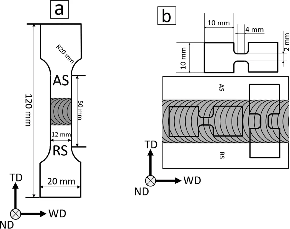
Fig. 3. Schematic illustration of both joint tensile specimens (a) and the SZ tensile specimen (b). Two types of SZ tensile specimens along the TD and the WD were carried out. The AS and the RS represent the advancing side and the retreating side, respectively. The transverse direction, the welding direction and the normal direction are abbreviated as TD, WD and ND, respectively.
The microstructures were observed using an optical microscope (OM, OLYMPUS BX51M) in both the SZ and the base metal (BM). The samples were mechanically polished with 4000# SiC abrasive paper and buffed with 1μm and 0.1μm alumina suspensions for the OM observations. For the optical observation, chemical etching was carried out with a solution containing 10g picric acid, 175ml ethanol, 25ml acetic acid, and 25ml distilled water for 15 s followed by 10 min of ultrasonic cleaning in high purity ethanol. An energy dispersive X-ray spectrometry (EDS) module attached to a scanning electron microscope (SEM, JEOL JSM-7001FA)was used to determine the morphology and the distribution of the intermetallic compounds. Electron backscattered diffraction (EBSD) was performed at the center of the SZ using via an Orientation Imaging Microscopy (OIM) method on a TexSEM Laboratories, Inc (TSL, OIM v7.0) system. The samples for EBSD were first mechanically polished in a similar way than for the optical observations. Then, they were electronically polished in a solution of 10ml perchloric acid and 90ml ethanol for 20 s at −30°C and at 15V. A transmission electron microscope (TEM, JEOL JEM-2001F) was used with an acceleration voltage of 300kV to observe the state of the particles. A focused ion beam (FIB, JEOL JIB-4500) was used to prepare the TEM samples.
The tensile tests were conducted at room temperature on a universal tensile test machine (SHIMAZU, AGS-10kNX).Two types of tensile specimens were used to evaluate the mechanical properties of the joint and the SZ (Fig. 3). AS and RS in Fig. 3 denote the advancing side and the retreating side of the FSW. The crosshead speeds for the tensile tests of the joint and the SZ were 1mm/min and 0.08mm/min,respectively, which is equivalent to a strain rate of 3.3×10⁻⁴.
3. Results and discussion
3.1. Microstructures
Ca addition reduces the defect-free welding parameter window of the FSW for Mg alloys [18,28]. A relatively high heat input is needed for AMX602 (AM60 with 2% Ca) to form a defect-free joint [18]. Such a narrow defect-free welding parameter window was also confirmed for AZX912 (AZ91 with 2% Ca) [28]. Fig. 4 shows optical images of the crosssection of the joints. No defect was observed in the AZ61 and AZX612 joints after asymmetric DFSW. The morphology of the SZ was barely affected by the addition of 2% Ca regardless of the conditions.
Fig. 5 shows OM images of the BM and the center of the SZ for both AZ61 (a-d) and AZX612 (e-h). The BM of AZ61 consists of mostly equiaxed grains with some twins. The average grain size of the AZ61 BM is 27μm. The AZX612 has uniform and equiaxed grains with many intermetallic compound particles. EDS was used to confirm the chemical composition of the intermetallic compound. The EDS analysis determined that there was only Ca and Al in the intermetallic compound. The atomic ratio of Al/Ca in the intermetallic compound was close to 2:1. Therefore, the intermetallic compounds in AZX612 seem to be Al2Ca [5–8]. The average grain size decreased from 27μm to 5μm after the addition of 2% Ca. A noticeable grain refinement in the BM upon Ca addition occurs in AZX612. In the SZ of AZ61, the grain size decreased when the lower tool rotation speed decreased.In AZX612, the grain size in the SZ hardly changed with the DFSW conditions. The Al2Ca particles also had a strong pinning effect to refine the grains. Since the size, the morphology, and the distribution of the intermetallic compound particles have a significant influence on the final microstructure and the mechanical properties. SEM was used to investigate the morphology and the distribution of the particles in AZX612 after DFSW. Fig. 6 shows the SEM images of three typical regions: (a) the BM, (b) the BM/SZ boundary, and (c)the center of the SZ. Both granular and irregular Al2Ca particles (white arrows in Fig. 6a) were present in the BM. The size of the particles in the BM ranged from below 1 μm to a maximum of ∼4 μm, and the morphology was not uniform.In the SZ, most particles were granular with a sub-micron size (white arrows in Fig. 6c). Moreover, the size and the morphology of the particles were more uniform in the SZ.
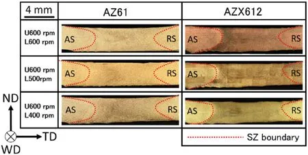
Fig. 4. Cross-section optical micrographs of the DFSW joints made from AZ61 and AZX612.
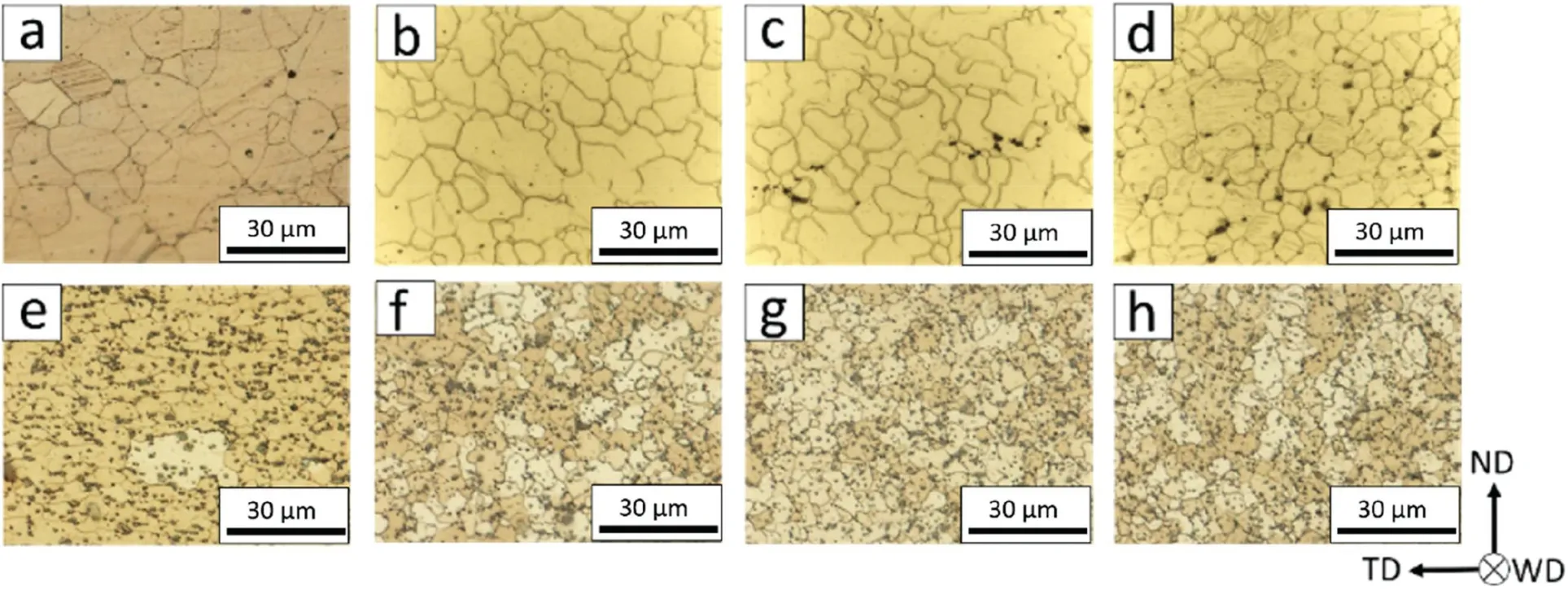
Fig. 5. Optical micrographs of AZ61 (a–d) and AZX612 (e–h). AZ61: (a) BM, (b) L600, (c) L500, (d) L400A. ZX612: (e) BM, (f) L600, (g) L500, (h) L400.

Fig. 6. SEM images of the BM (a), the SZ/BM boundary (b), and the SZ center (c).
This indicates that the intermetallic compound particles were refined during the DFSW.
Figs. 5 and 6 show that the addition of 2% Ca does not form any defects during asymmetric DFSW but affects the final microstructure in the SZ. The Al2Ca intermetallic compound is refined during the DFSW and uniformly distributed in the SZ. A significant grain refinement (∼10μm to∼5μm) occurred in the SZ upon the addition of 2% Ca. The Al2Ca particles contribute to the grain refinement by inducing particle-stimulated nucleation (PSN) and prevent the movement of the grain boundary during the grain growth [29]. The average grain size decreases in AZ61 when the lower tool rotation speed decreased.However,the average grain size hardly changed in AZX612 regardless of the DFSW conditions.
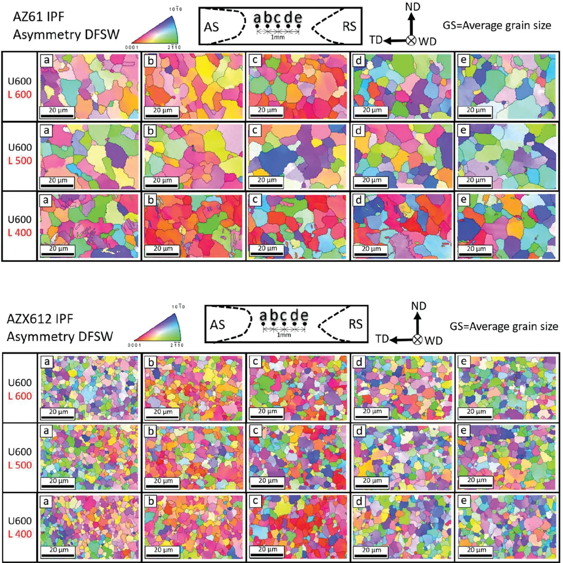
Fig. 7. Inverse pole figures obtained in several regions along the transverse centerline in the cross-section of the SZ (AZ61 and AZX612). Five regions (a–d)were measured by EBSD. Region c is at the center of the SZ. Region a and region b are 2mm and 1mm from the center of the SZ on the AS, respectively.Region d and region e are 1mm and 2mm from the center of the SZ on the RS, respectively.
3.2. Texture evolution
The mechanical properties of Mg alloys are closely related to their crystal orientation distribution (texture) due to the HCP structure. Mg alloys with a randomized crystal orientation and excellent mechanical properties have been obtained by asymmetric DFSW [26,27]. The addition of Ca can also significantly enhance the mechanical properties and the stretch formability due to a decrease in the (0001) texture strength of hot-rolled Mg alloy [29,30]. The optimization of the mechanical properties is related to texture randomization induced by PSN and the activation of the prismatic and pyramidal
To determine the effect of the addition of 2% Ca on the crystal orientation in the SZ of AZX612, EBSD was carried out in the SZ of both AZ61 and AZX612. The scanned regions and the crystal orientation color maps (inverse pole figure with color scheme triangle) are shown in Fig. 7 for AZ61 and AZX612. Five representative regions were selected: (a)2mm from the center of the stir zone on the AS, (b) 1mm from the center of the stir zone on the AS, (c) the center of the stir zone, (d) 1mm from the center of the stir zone on the RS, and (e) 2mm from the center of the stir zone on the RS.The grain size distributions in AZ61 and AZX612 are shown in Fig. 8, The a–e regions are abbreviated as AS2, AS1, CT,RS1, and RS2, respectively. In AZ61, the average grain size between the five scanned regions was 12.2±1.6μm at a lower tool rotation speed of 600rpm. When the lower tool rotation speed decreased to 500rpm and 400rpm, the average grain size in the SZ decreased to 11.5±0.8μm and 9.7±1.1μm,respectively. The coarsening of the grains in the SZ originates from the higher peak temperature and the longer subsequent annealing time at a higher tool rotation speed [33–37]. However, the grain size in the SZ of AZX612 shows a weak correlation with the heat input. At a lower tool rotation speed of 600rpm, the average grain size in the SZ of AZX612 is 4.9±0.2μm.When the lower tool rotation speed decreased to 500rpm and 400rpm, the average grain size was 4.8±0.2μm and 4.7±0.1μm, respectively. The Al2Ca particles refine the grain after the FSW. Moreover, the Al2Ca particles stabilize the grain size and reduce the sensitivity to the different heat inputs.

Fig.8. Average grain size at several locations along the transverse center line in the cross-section of the SZ. The CT denotes the center of the stir zone.The AS2 and AS1 represent the 2mm and 1mm to the CT at the advancing side. The RS2 and RS1 mean the 2mm and 1mm to the CT at the retreating side.
Additionally, the addition of 2% Ca caused a noticeable difference in the grain morphology. In Fig. 7, the grains of AZ61 in the SZ are non-equiaxed and with different sizes and morphologies. Grain boundary bulging due to strain induced boundary migration was observed. Meanwhile, small grains with different orientations from the adjacent grains at the triple junction were observed. These characteristics indicate a discontinuous recrystallization.The grain size distribution and the morphology are more uniform after the addition of 2%Ca. Fig. 9 shows the low angle boundary (LAB, < 15°) fraction in the SZ. In AZ61, the LAB fraction increases rapidly when the lower tool rotation speed decreases. The average LAB fraction increased from 21.0% (L600) to 27.9% (L500)and 30.5% (L400). A higher lower tool rotation speed leads to a higher peak temperature. Therefore, more sub-structures were consumed by the recovery and recrystallization. Moreover, the LAB fraction is different on the AS and on the RS.Previous studies showed that the difference originates from the difference in the strain rate, the total strain, and the temperature distribution between the AS and the RS [38,39]. In AZX612, the LAB fraction is hardly affected by changing the DFSW parameters. The average LAB fractions in the SZ of AZX612 are 22.1%, 21.4%, and 23.1% for L600, L500, and L400, respectively. Therefore, the addition of Ca reduces the LAB fraction. As seen in Fig. 6c, a large number of Al2Ca particles with various sizes are introduced by the addition of 2% Ca. Particles larger than 1 μm can induce PSN, which decreases the LAB fraction and yields a more random crystal orientation. Fig. 10 shows (a) the Kernel average misorientation (KAM) map around a large Al2Ca particle and (b) the bright-field TEM image and diffraction pattern of three adjacent grains. The grains around the large Al2Ca particles are dislocation-free and the different orientations indicate the occurrence of PSN during the discontinuous recrystallization.Therefore, it can be concluded that the addition of 2% Ca has several effects on the microstructure and the LAB fraction; i.e., (1) it refines the grain and stabilizes the grain size in the SZ due to a pinning effect, and (2) it decreases the LAB fraction by affecting the discontinuous recrystallization process.
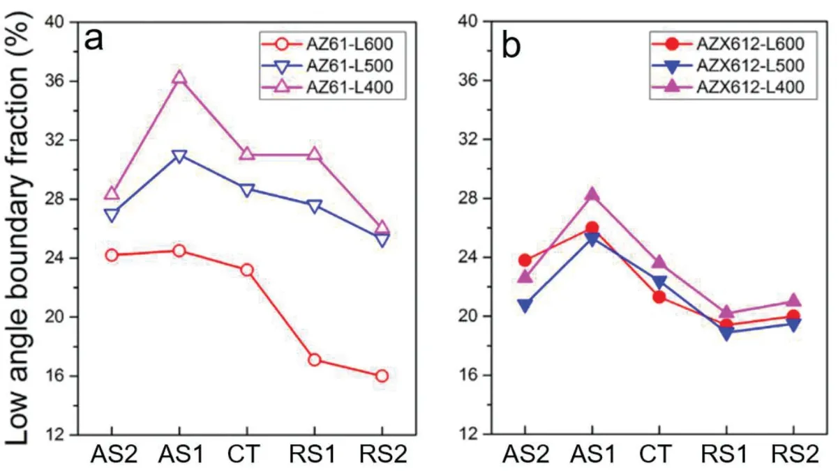
Fig. 9. LAB fraction of the (a) AZ61 SZ and the (b) AZX612 SZ.

Fig. 10. (a) Kernel Average Misorientation (KAM) map around a large Al2Ca particle. (b) Bright-field TEM image and diffraction pattern of three adjacent grains.
Because of the significant difference between the critical resolved shear stress (CRSS) of the basal slip system and that of non-basal slip systems, such as prismatic, pyramidal, and
The weakening of the (0001) texture upon the addition of Ca in a thermally mechanically processed Mg alloy has been reported previously [29–32]. The first principle calculation reveals that the general stacking fault energies (GSFEs) of {0001}<10–10> for the basal partial slip and{1100}<11–20> for the prismatic perfect slip are reduced upon the addition of Ca [31,32]. On the other hand,thermally activated processes prevent basal slip and relatively favor the prismatic slip by affecting the CRSS. Since asymmetric DFSW is a thermal mechanical process, it is considered that the weakening of the (0001) texture observed in this study originates from this same mechanism. Overall, it is confirmed that the addition of Ca significantly reduces the(0001) texture strength in the SZ.
3.3. Mechanical properties
3.3.1. Tensile properties of the joint
Fig. 13 shows the yield strength (YS), the ultimate tensile strength (UTS), and the elongation to failure rate (EI)of the (a) AZ61 and (b) AZX612 joints. In AZ61, the YS,UTS, and EI increased when the lower tool rotation speed decreased. Only the L400 joint fractured at the HAZ, the L500 and L600 joint fractured at the AS side in the SZ. When the lower tool rotation speed decreased from 600rpm to 400rpm,the YS and the UTS of the joint increased by 24.1% and 13.2%, respectively. The (0001) texture strength at the CT in the SZ of L400 is approximately 16% higher than that in L600, but the average grain size of L400 is approximately 35% lower. Therefore, the change in the joint strength is significantly affected by the grain refinement with the lower heat input. Moreover, the ductility of the joint is also improved when decreasing the lower tool rotation speed. The EI of the AZ61 joint increases by 20.8% between L600 and L400. The strength and the ductility of the joint increase simultaneously when the heat input decreases.
In conclusion, the AZ61 joint shows better mechanical properties for a lower heat input. With a lower heat input,the average grain size in the SZ decreases when the LAB fraction increases (Figs. 8 and 9). The strength of the SZ is enhanced by the grain refinement and the preservation of the sub-structures(higher LAB fraction)under a lower heat input.Even though a higher (0001) texture strength has a negative effect on the ductility of the joint, the decrease in the grain size and the higher LAB fraction contributes to increasing the strength of the joint.
The mechanical properties in AZX612 joints follow a different trend than for AZ61. The L400 joint fractured at the
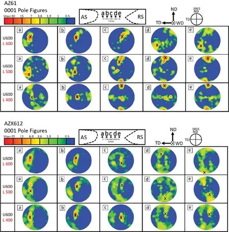
Fig. 11. (0001) pole figures obtained in several regions along the transverse center line in the cross-section of the SZ (AZ61 and AZX612). The max (0001)texture strength points are marked with black X symbols.
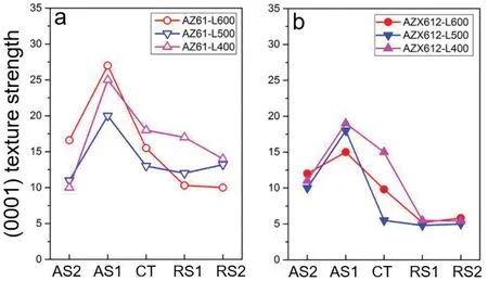
Fig. 12. (0001) texture strength of the measured regions in the SZ of (a) the AZ61 and (b) the AZX612.
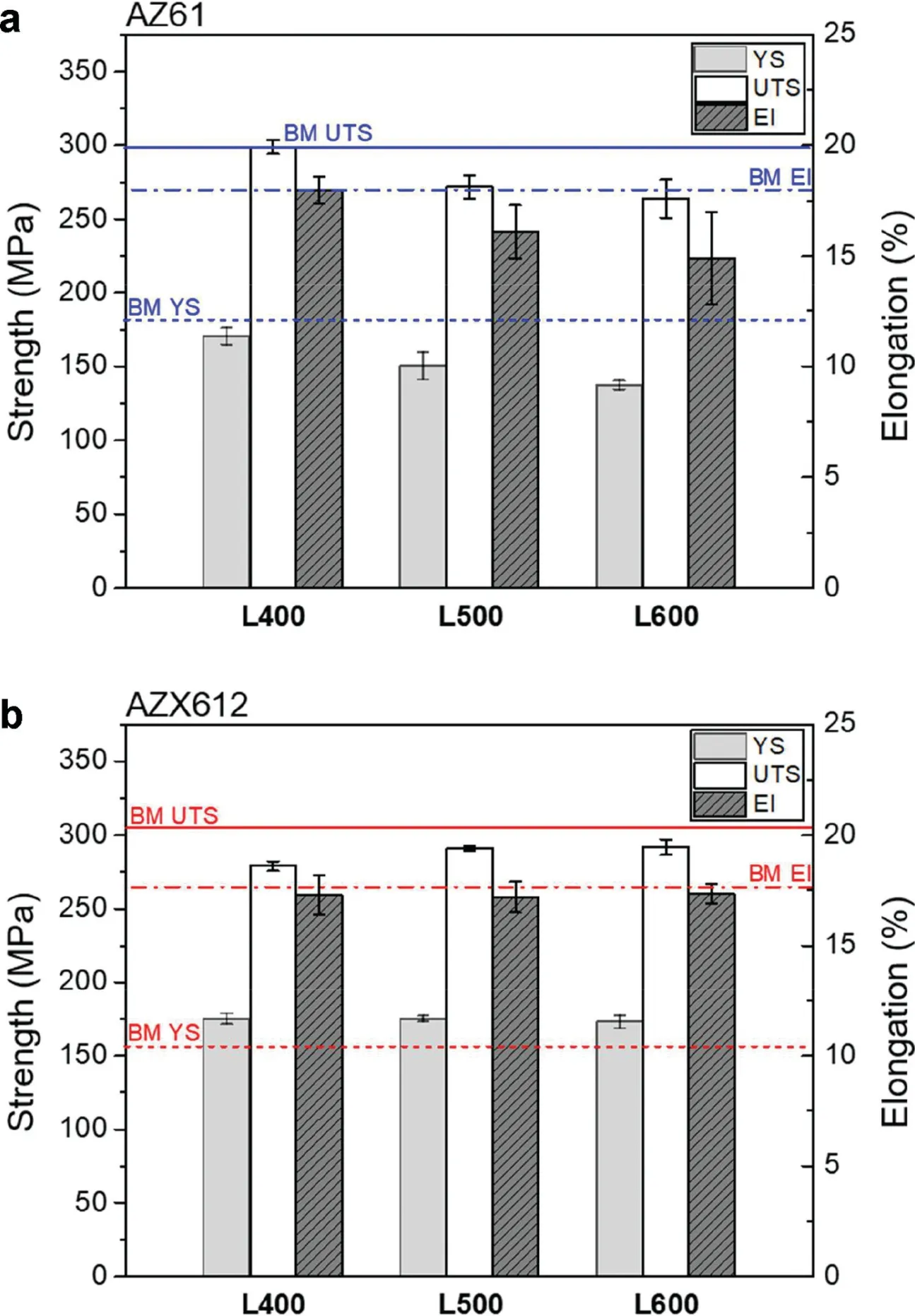
Fig. 13. Transverse tensile properties of the a) AZ61 and b) AZX612 DFSW joints.
center of the SZ, the L500 and L600 fractured at the AS side close to the HAZ. The YS only slightly changes for a different heat input and remains constant around 175MPa. The UTS and the EI show a similar tendency than the YS. The UTS of the AZX612 joints remains around 286MPa. The EI of the joints remains close to 17%, which is equivalent to the value of the BM. As shown in Figs. 8 and 9, there is no apparent difference between the average grain size and the LAB fraction in the SZ for a different heat input. This explains the lack of an observable difference in the mechanical properties of the AZX612 joints.
3.3.2. Tensile properties of the SZ
To evaluate the relationship between the mechanical properties and the microstructure (texture), local tensile tests were conducted in the SZ along the TD and the WD. Due to the significant changes in the (0001) texture strength in the SZ,local tensile tests along the WD were carried out at the center of the stir zone (CT) and at AS1. The strain-stress curves are shown in Fig. 14.
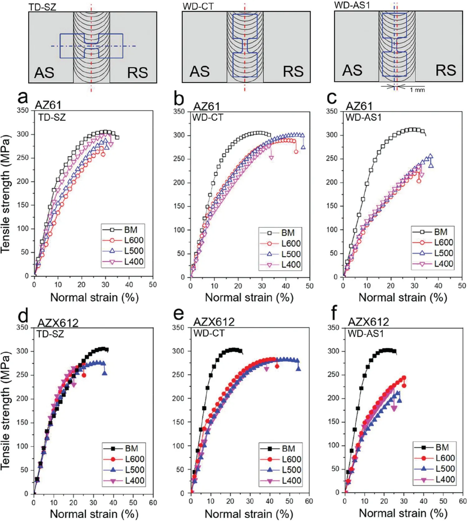
Fig. 14. Tensile properties at the SZs of the AZ61 sample (a) along TD, (b) at SZ along WD, and (c) at AS1 along WD. Tensile properties at the SZ of the AZX612 sample (d) along TD, (e) at SZ along WD, and (f) at AS1 along WD. The schematic illustration figures above the strain-stress curves show the geometric detail about the tensile test specimen of TD-SZ, WD-CT and WD-AS1.
The UTS along the TD in AZ61 explained why the ductility of the joint increases when the grain size decreases(Fig. 14a). In the tensile test along the TD, the UTS increases when the lower tool rotation speed decreases. The UTS of L400, L500, and L600 along TD are 302MPa, 281MPa, and 272MPa, respectively. Comparatively, the UTS of the BM is 305MPa. The SZ of L400 has the highest UTS and is the closest to that of the BM. Therefore, the excellent ductility of the L400 joint results from the uniform tensile deformation of the whole joint because the SZ has a similar UTS as the BM. Since the TD tensile specimen contains all five regions shown in Fig. 7 and their (0001) texture and LAB fraction are drastically different, the tensile tests along the WD were carried out at the CT or at AS1 to focus on the effects of the texture on the mechanical properties.The results of the tensile tests along the WD at the CT and at AS1 are shown in Fig.14b and c, respectively. The specimen for WD has a noticeably different elongation (Fig. 14b). The plastic elongation of L400, L500, and L600 along the WD at CT is 25.2%, 40.6%,and 35.1%, respectively. The plastic elongation along WD at AS1 dramatically decreases to 21.3%, 22.5%, and 27.0% for L400, L500, and L600, respectively (Fig. 14c). The noticeable drop in the UTS and the fracture during work hardening could also be confirmed in Fig. 14c.
The UTS in the AZX612 SZ along the TD shows a similar value (around 280MPa) for the tensile tests of the joints (Fig.14d). The results of the tensile tests along the WD at CT and AS1 are shown in Fig. 14e and f, respectively. Similarly, the plastic elongation along the WD in AZ61 decreases significantly from the CT to AS1. The plastic elongation of the CT along WD is 28.3%, 45.2%, and 35.7% for L400, L500 and L600, respectively. The plastic elongation at AS1 along the WD drops to 14.1%, 18.6%, and 20.2% for L400, L500,and L600, respectively. This confirms that the addition of Ca further deteriorates the plastic elongation in the high (0001)textured region.
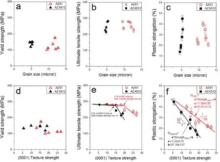
Fig. 15. Relationship between the grain size and (a) the yield strength, (b) the ultimate tensile strength, and (c) the plastic elongation. Relationship between the (0001) texture strength and (d) the yield strength, (e) the ultimate tensile strength, and (f) the plastic elongation.
Fig. 15 summarizes the relationship between the grain size and(a)the yield strength,(b)the ultimate tensile strength,and(c) the plastic elongation, as well as the relationship between the (0001) texture strength and (d) the yield strength, (e)ultimate tensile strength, and (f) the plastic elongation. Given the uniformity of the microstructure of the tensile specimen,only the results of WD-CT and WD-AS1 were summarized.There is no significant relationship between the grain size and these mechanical properties. The grain size variation without any Ca addition is significant, as shown in Fig. 8. After the addition of 2% Ca, the grain size does not vary significantly for the different welding parameters. Additionally, the LAB fractions in AZ61 change with the grain size whereas the LAB fraction remains almost identical after the addition of Ca. However, the mechanical properties of AZX612 show a significant variation even for the same grain size and a similar LAB fraction. The UTS of AZ61 drops when the (0001)texture exceeds 20 whereas the UTS of AZX612 drops when the (0001) texture exceeds 15 (Fig. 15e). The strain-stress curves of Fig. 14c and f illustrate that a fracture occurred during the work hardening stage of the tensile tests in the high (0001) texture strength region (AS1). The decrease of the critical (0001) texture strength from 20 in AZ61 to 15 in AZX612 and the deterioration of the UTS after the addition of 2% Ca originates from the introduction of a large number of Al2Ca particles, as shown in Fig. 5. The particles prevent the movement of the dislocations during the work hardening stage, which leads to an early strain concentration and a fracture. Fig. 15f shows the variation of the plastic elongation with the (0001) texture strength. The decrease in the plastic elongation when the (0001) texture strength increases is similar in AZ61 and in AZX612. Fig. 15f clearly shows that the addition of Ca deteriorates the plastic elongation for the same (0001) texture strength. For instance, AZ61 has an elongation of 25.2% for a (0001) texture strength of 18 and AZX612 decreases to 18.6%. Meanwhile, the slope of the linear fit further decreases from −1.28 for AZ61 to −2.22 for AZX612. In general, a decrease in the (0001) texture strength optimizes the plastic elongation in the Mg alloys[26–32]. However, the large number of particles present decreases the plastic elongation even for a relatively low (0001)texture strength in AZX612. This explains the decrease in the UTS when the (0001) texture strength increases. The UTS has a similar value at the low (0001) texture strengths because the plastic elongation is sufficient for the material to reach the maximum uniform elongation for the UTS. When the (0001) texture strength increases to a critical value (20 for AZ61 and 15 for AZX612), fracture occurs during the uniform elongation stage. Therefore, when the (0001) texture strength exceeds the critical value (Fig. 15e), the higher(0001) texture strengths yield a lower plastic elongation,which leads to a decrease in the UTS. The addition of Ca decreases the critical (0001) texture strength value from 20 to 15 because the particles introduced prevent the movement of dislocations, which results in a lower plastic elongation even for the same (0001) texture strength (Fig. 15f).
4. Conclusion
The effects of the addition of 2% Ca on the microstructure and the mechanical properties of the AZ61 joints treated by asymmetric DFSW were investigated. The results can be summarized as:
(1) The Ca addition shows a remarkable grain refinement during asymmetric DFSW. The grain refinement originates from a large amount of intermetallic Al2Ca that provides a strong pinning effect. The Al2Ca particles restrain the growth of the grains during the subsequent annealing stage after DFSW. A similar grain size is obtained regardless of the DFSW conditions when Ca is added;
(2) The Ca addition decreases the (0001) texture strength in the SZ. The activation of the non-basal slip and the PSN effect by the addition of 2%Ca reduces the(0001)texture strength. Therefore, a much lower (0001) texture strength is obtained in the SZ of AZX612 than for AZ61;
(3) The plastic elongation of the SZ is mainly affected by the local (0001) texture strength. The increase in the(0001) texture strength decreases the plastic elongation.The Ca addition further decreases the plastic elongation due to the introduction of a large number of particles;
(4) The critical (0001) texture strength that determines the UTS is revealed.A high(0001)texture strength leads to fracture during the work hardening stage,which yields a low UTS. The critical (0001) texture strength decreases from 20 to 15 after Ca addition because it requires a random texture to reach the UTS after the introduction of particles.
Declaration of Competing Interest
The authors declare that they have no known competing financial interests or personal relationships that could have appeared to influence the work reported in this paper.
Acknowledgment
This study was partially supported by the New Energy and Industrial Technology Development Organization(NEDO) under the “Innovation Structural Materials Project(Future Pioneering Projects)”.
杂志排行
Journal of Magnesium and Alloys的其它文章
- Latest research advances on magnesium and magnesium alloys worldwide
- Advances in coatings on biodegradable magnesium alloys
- Stability of twins in Mg alloys – A short review
- A review on thermal conductivity of magnesium and its alloys
- Effect of pre-deformation on microstructure and mechanical properties of WE43 magnesium alloy II: Aging at 250 and 300 °C
- Constitutive behavior and processing maps of a new wrought magnesium alloy ZE20 (Mg-2Zn-0.2Ce)
