Experimental investigation of velocity fluctuations in a radial diffuser pump*
2015-02-16FENGJianjun冯建军LUOXingqi罗兴锜BENRAFriedrichKarlDOHMENHansJosef
FENG Jian-jun (冯建军), LUO Xing-qi (罗兴锜), BENRA Friedrich-Karl, DOHMEN Hans-Josef
1. State Key Laboratory Base of Eco-Hydraulic Engineering in Arid Area, Xi’an University of Technology, Xi’an 710048, China
2. Department of Mechanical Engineering, Faculty of Engineering, University of Duisburg-Essen, Duisburg 47048, Germany, E-mail: fengjianjunxaut@163.com
Experimental investigation of velocity fluctuations in a radial diffuser pump*
FENG Jian-jun (冯建军)1,2, LUO Xing-qi (罗兴锜)1, BENRA Friedrich-Karl2, DOHMEN Hans-Josef2
1. State Key Laboratory Base of Eco-Hydraulic Engineering in Arid Area, Xi’an University of Technology, Xi’an 710048, China
2. Department of Mechanical Engineering, Faculty of Engineering, University of Duisburg-Essen, Duisburg 47048, Germany, E-mail: fengjianjunxaut@163.com
(Received April 22, 2014, Revised August 4, 2014)
The strong interaction in a radial pump due to the relative movement between the impeller and the diffuser may excite not only strong pressure fluctuations but also velocity fluctuations. In this paper, the laser Doppler velocimetry (LDV) technique is successfully applied to measure the periodic flow field in a radial diffuser pump with low-specific speed, in order to investigate the velocity fluctuations caused by the impeller-diffuser interactions both in the impeller and diffuser regions. The velocity fluctuations in the impeller region are quantitatively examined at different radial positions, and the flow structure at the radial gap between two flow components is analyzed at different relative positions. In addition, the downstream effect on the diffuser flow is quantitatively and qualitatively assessed and compared with the turbulence effect.
laser Doppler velocimetry (LDV), radial pump, impeller-diffuser interaction, velocity fluctuations
Introduction
The radial pumps are turbo-machines used for transporting or raising a specified volume flow to a specified pressure level, and are extensively used in industry. The inside flow structure is very complicated and strongly unsteady, and it is induced by a strong interaction due to the relative movement between the rotating impeller and the stationary diffuser, known as the impeller-diffuser interaction. It is reported that the interaction in between can produce strong pressure fluctuations both upstream the impeller flow and downstream the diffuser flow[1-3], along with velocity and turbulence fluctuations[4,5].
The pressure fluctuations in radial diffuser pumps were extensively studied by both numerical and experimental methods, such as Wang and Tsukamoto[6], Furukawa et al.[7], Guo and Maruta[8], Yuan et al.[9]and Ni et al.[10]. It is revealed that the unsteady interactions can generate strong pressure fluctuations upstream and downstream, to produce high dynamics forces and cause vibrations, noises and even damages in some extreme cases.
The velocity fluctuations in radial pumps were studied with particle image velocimetry (PIV) measurements[11-14]and axial pumps[15]. Another non-contact method of measuring velocities is the laser Doppler velocimetry (LDV), which is considered to be more accurate due to its direct measurements at the points of interest. The LDV measurements in radial pumps were conducted to study unsteady flows there. Akhras et al.[16]and Hajem et al.[17]applied the LDV to investigate the flow field near an impeller outlet. Pintrand et al.[18]measured the velocity field in the impeller outer part and also in the diffuser region. Nicholas et al.[19]studied the impeller internal flow fields using the LDV technique. Akhras et al.[20]applied the LDV to investigate the influence of the downstream diffuser on the impeller flow field. Feng et al.[21]applied the LDV in a radial pump to investigate unsteady effects related to the unsteady velocities. Their studies improved the understanding of the unsteady flow characteristics in radial diffuser pumps. However, the velocity fluctuations caused by the impeller-diffuser interaction remain an issue for further studies.
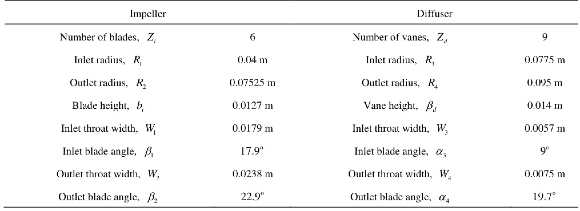
Table1 Pump geometry
In this paper, the LDV technique is successfully applied to measure the unsteady flow in the impeller and the diffuser of a radial diffuser pump, in order to examine the velocity fluctuations caused by unsteady interactions between the impeller and the diffuser.
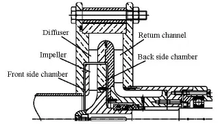
Fig.1 Meridional section of the pump stage
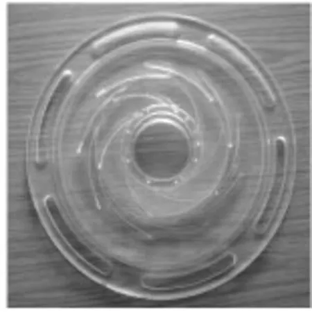
Fig.2 A view of the pump
1. Experimental procedures
1.1 Pump geometry
The radial pump stage is in a low-specific speed, which is composed of a shrouded six-blade impeller and a nine-vane diffuser. The impeller blade is constructed with one single arc and in constant thickness, with inlet radius R1=0.04 mand outlet radius R2= 0.07525 m. The blades are arranged with blade angle of β=17.9oat the inlet andβ=22.5oat the outlet.
12The radius for the diffuser inletR3is 0.0775 m, with a radial gap of 0.00225 m, which is relatively small and is assumed to generate very strong unsteady effects due to the rotor-stator interaction. Table 1 shows some important parameters for the pump stage, and Fig.1 shows the meridional section of the pump stage. For the optical measurement, the whole pump stage including the impeller, the diffuser and the return channel is constructed entirely with Plexiglas. Figure 2 shows an overview of the impeller and the diffuser.
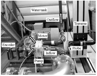
Fig.3 Pump test stand with LDV
1.2 LDV measurements
Figure 3 shows the pump test stand equipped with the LDV measuring system. The pump stage is driven by a motor connected with a belt, and its rotation frequency can be increased gradually to 50 Hz with a minimum step of 0.1 Hz. A water tank of 3 m3in volume is used to feed the water into the pump and also recollect the water out of the pump. An electromagnetic flow meter is installed behind the pump to measure the flow rate. For the LDV system, a laser light is generated by an Argon-Ion laser. Two laserbeams, the green one (514.5 nm) and the blue one (488 nm), are produced by a beam separator for an optics probe for transmitting and receiving signals. The probe is mounted on a two-dimensional traverse system, whose movement is controlled by software to make successive measurements at required points.

Fig.4 LDV measurement points

Fig.5 Velocity decomposition of signals in LDV
The measurement region is shown in Fig.4, located at the midspan, i.e., the half blade height plane as indicated in the meridional section in the right subfigure, covering a part of the impeller region and a full diffuser channel. The encoder fixed on the pump shaft produces one pulse in a predefined impeller position during each revolution, which is utilized to synchronize the measurement at the impeller circumferential position. In the impeller, the range of measurement points at 8 radial positions covers one whole diffuser pitch. In the diffuser, more than 210 points are selected. At each point, 100 000 sets of data are recorded with the coincidence model, in which each set of two velocity signals are taken simultaneously.
1.3 Data post-processing
Measurements are conducted only inxandy directions, as indicated in Fig.4, and the velocity in the z-axis direction is not measured. The relative impeller positionφis utilized to associate the impeller relative circumferential position with the diffuser during the impeller rotation.φ=0ois the relative impeller position when the pre-defined impeller blade trailing edge approaches the leading edge of a pre-defined diffuser vane.
Figure 5(a) shows the velocity signals from the LDV measurements, each measured signal is synchronized with time in the range between 0 andT(the pump rotation period) with the function of resetting time each cycle realized by the shaft encoder. Then, the signals are sorted into 360 bins (one degree for each bin width), and each bin represents a particular impeller positionφ. During each bin, the mean (arithmetic-average) velocities () and the velocity standard deviations (are calculated taken account of all signals falling into the bin width, as shown in Fig.5(b) and expressed in Eq.(1) for two velocity componentsuandv. The turbulence intensityTu is defined in Eq.(3) based on the velocity standard deviation components. Moreover in cylindrical coordinates, the absolute circumferential velocity Cuand the radial velocity Crare obtained from Eq.(4) according to the azimuth angleφ

2. Results and discussions
Results discussed in the following section are for the design condition of the pump: the rotating speed ndes=1450 rpmand the flow rate Qdes=4.5l/s.
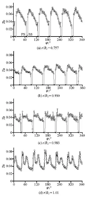
Fig.6 Evolution of turbulence intensity in impeller
Figure 6 shows the turbulence intensity distributions in the impeller region at four measurement points, positioned at a radial plane of φ=70o(Fig.4). Each measurement point is fixed in the absolute coordinate system, resulting in different circumferential positionsφwithin one impeller revolution.
The similarity of the turbulence intensity among six impeller channels can be still observed despite some noise, showing the consistence of the measured data set and the uniformity of the flow. For all investigated points, the turbulence intensityTu near the impeller suction side is larger than that near the pressure side, and the largestTu is located near the impeller suction side. This is due to the unsteady effects from the leakage flows in the front side chamber of the impeller, as is confirmed by the CFD results not presented here. The highest turbulence intensity near the impeller suction side keeps decreasing from around 7.5% at r/ R2=0.757to 5.3% at r/ R2=0.930. This is because the unsteady leakage flow effect attenuates with the increase of the radial distance to the outlet of the front side chamber near the impeller inlet[ 12]. However, the highest turbulence intensity on the pressure side stays at around 3%. Moving from r/ R2=0.983to r/ R2=1.01, the turbulence intensity on the pressure side remains 3%, but the highestTu near the impeller suction side increases and reaches up to 8%. In addition, two peaks are generally observed for each impeller pitch. The propagation of the impeller wake and its interaction with the diffuser leading edges contribute to this high magnitude ofTu and the mentioned two peaks.

Fig.7 Velocity triangle
The relative flow angleβis defined in Fig.7 and expressed as in Eq.(5). Figure 8 shows the relative flow angle distributions at the radial position r/ R2= 1.01, which is located in the radial gap region between the impeller and the diffuser.

Obviously,βexperiences a very strong variation in the circumferential direction, influenced not only by the location of the impeller trailing edge (marked with rectangles on the top) but also by the location of the diffuser vane leading edge (marked with ellipses on the bottom).The flow angleβpredicted by the LDV is smaller than the design value (β2= 22.5o)nearly in the whole circumferential range, as a result of the slip effect due to the finite number of the impeller blades. Negative values ofβare observed near each diffuser leading edge due to the local back flow. In addition, the peak-to-peak difference ofβin the circumferential direction is as high as 50o. Notice thatβhas a tendency to increase in the impeller wake region, decreasing when the impeller wake begins to impinge the diffuser leading edge (Fig.8(b)) andincreasing after the impingement. This phenomenon was also reported in axial turbines[22].

Fig.8 Comparison of relative flow angles in the radial gap between the impeller and diffuser,r/ R2=1.01
The stator unsteady intensitySuis defined to identify quantitatively the impeller rotation effect on the diffuser flow structure, which is expressed as in Eq.(6) based on the periodic velocity components calculated by excluding the time-averaged components from the phase-averaged components in Eq.(7). In addition, the averagedSuandTu can be obtained from Eq.(8).
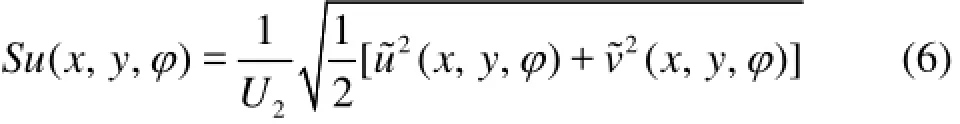
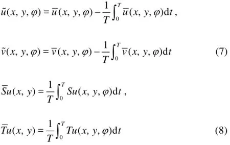
Figure 9 shows a comparison betweenTuand Suat three measuring points in the diffuser. For the point in the semi-vaned region near the diffuser inlet (P1), it is found that the peak value ofSureaches up to 12%, nearly twice larger than that ofTu , which means thatSu is more sensitive to the impeller position thanTu in this region. In addition, six peaks in both distribution curves correspond very clearly to six blades of the impeller. Moving to the point located behind the diffuser inlet throat (P2),Sudecreases greatly and becomes smaller thanTuin the whole range. At the point behind the diffuser outlet throat (P3), the domination of the impeller blade passing frequency on SuandTu becomes very weak, andTustays at about 4% whileSufluctuates around less than 1%.

Fig.10 Stator unsteady intensity Suin diffuser
Figure 10 shows the contours of the stator unsteady intensitySu at two impeller positions. The highestSu is around 10%, taken at the position just behind the trailing edge of the impeller blade.Su in the semi-vaned region stays in general at a high level of about 6%.

Fig.11 Comparison between stator unsteady intensity and turbulence intensity in diffuser
Figure 11 shows several comparisons of the contours between the turbulence intensityTu and the stator unsteadinessSu , including the time averages and also the peak-to-peak differences (the difference between the maximum and the minimum) in the complete diffuser passage. It is obvious thatSu in Fig.11(a) on the diffuser suction side is much higher than thaton the pressure side, indicating that the flow on the suction side changes more strongly during the impeller rotation, i.e., is more influenced by the impeller rotation. This might be due to the fact that the suction side is closer to the trailing edge of the impeller blade as compared to the pressure side of the diffuser vane. Furthermore, in the front part of a diffuser pitch in the circumferential direction (based on the rotation direction of the impeller) one sees the highest Su reaching 7%. This suggests that the flow field in this region is the most sensitive to the impeller relative position, and the diffuser leading edge contributes to this effect. For Tuin Fig.11(b), a higher value is observed near the diffuser suction side in the semi-vaned region and in the diffuser wake region. In a further analysis, one sees thatSuis larger than or at least comparable to Tuin the semi-vaned region, which is very clearly seen by the comparison in Fig.12(a). Here it is indicated that both the impeller orientation effect and the turbulence effect are dominant for the flow in that region. Behind the inlet throat of the diffuser,Suis observed to be generally smaller than 2%. However,Tu remains to be about 2% in magnitude. Behind the outlet throat of the diffuser, the stator unsteady intensity keeps decreasing and is now much lower than the turbulence intensity, as shown in Fig.12(b). Moreover, the peak-to-peak distribution of Sushown in Fig.11(c) is similar to the averaged distribution, showing that a higherSuis accompanying by a higher peak-to-peak value. The peak-to-peak distribution of Tu in Fig.11(d) shows a highest value of around 6%.

Fig.12 Comparison of TuandSu in diffuser
3. Conclusions
The periodic flow field in a radial diffuser pump stage is measured by the LDV. The attention is paid to the velocity fluctuations caused by the unsteady interactions between the impeller and the diffuser. It is shown that the distribution of the relative flow angle βnear the impeller outlet is strongly non-uniform. Consequently, different inlet conditions are produced for the downstream diffuser. The high turbulence intensity on the impeller suction side induced by the leakage flow is nearly in the same magnitude as in the impeller wake, around 8% based on U2, and it decreases slightly with the radial position. The turbulence intensity on the pressure side stays at about 3% for all measured radial positions, much smaller than on the suction side.
In the diffuser, the stator unsteady intensity assumes a peak value of about 12% near the diffuser inlet, twice as high as that of the turbulence intensity in that region. In addition, the time-averaged values of both at the diffuser inlet are generally around 5%-6%, slightly fluctuating depending on the circumferential position. It is found that both the impeller orientation effect (i.e., the stator unsteady intensity) and the turbulence effect play important roles for the flow structure in the semi-vaned region ahead of the inlet throat of the diffuser. In other words, the unsteady intensity from the impeller rotation is larger than or at least comparable to the turbulence intensity. Behind the diffuser inlet throat, the stator unsteady intensity diminishes greatly and is lower than the turbulence effect. The impeller orientation effect nearly vanishes behind the outlet throat of the diffuser, while the turbulence intensity does not decay but still remains in a relatively high level.
[1] ARNDT N., ACOSTA A. J. and BRENNEN C. E. et al. Rotor-stator interaction in a diffuser pump[J]. Journal of Turbomachinery,1989, 111(3): 213-221.
[2]PAVESIG.,CAVAZZINIG. and ARDIZZON G. Pressure instabilities in a vaned centrifugal pump[J]. Proceedings of the Institution of Mechanical Engineers, Part A: Journal of Power and Energy, 2011, 228(4): 930-939.
[3] JAPIKSE D., MARSCHER W. D. and RAYMOND M. B. F. Centrifugal pump design and performance[M]. Vermont, USA: Concepts ETI Incorporated, 1997.
[4] SINHA M., KATZ J. Quantitative visualization of the flow in a centrifugal pump with diffuser vanes, part I: On flow structures and turbulence[J]. Journal of Fluids Engineering, 2000, 122(1): 97-107.
[5] SINHA M., KATZ J. Quantitative visualization of the flow in a centrifugal pump with diffuser vanes, part II: Addressing passage averaged and LES modeling issues in turbomachinery flow[J]. Journal of Fluids Engineering, 2000, 122(1): 108-116.
[6] WANG H., TSUKAMOTO H. Experimental and numerical study of unsteady flow in a diffuser pump at offdesign conditions[J]. Journal of Fluids Engineering, 2003, 125(5): 767-777.
[7] FURUKAWA A., TAKAHARA H. and NAKAGAWA T. et al. Pressure fluctuation in a vaned diffuser downstream from a centrifugal pump impeller[J]. International Journal of Rotating Machinery, 2003, 9(1): 285- 292.
[8] GUO S., MARUTA Y. Experimental investigations on pressure fluctuations and vibration of the impeller in a centrifugal pump with vaned diffuser[J]. JSME International Journal, Series B: Fluids and Thermal En- gineering, 2005, 48(1): 136-143.
[9] YUAN Shou-qi, NI Yong-yan and PAN Zhong-yong et al. Unsteady turbulent simulation and pressure fluctuation analysis for centrifugal pumps[J]. Chinese Journal of Mechanical Engineering, 2009, 22(1): 64-69.
[10] NI Yong-yan, YUAN Shou-qi and PAN Zhong-yong et al. Diagnosing the running condition of pump by its vibration character[J]. Drainage and Irrigation Machi- nery, 2007, 25(2): 49-52(in Chinese).
[11] WUIBAUT G., BOIS G. and DUPONT P. et al. PIV measurements in the impeller and the vaneless diffuser of a radial flow pump in design and off-design operating conditions[J]. Journal of Fluids Engineering, 2002, 124(3): 791-797.
[12] FENG J, BENRA F.-K. and DOHMEN H. J. Unsteady flow visualization at part-load conditions of a radial diffuser pump: by PIV and CFD[J]. Journal of Visuali- zation, 2009, 12(1): 65-72.
[13] CAVAZZINI G.,CAVAZZINIG. and ARDIZZON G. Validation of an analysis method for particle image velocimetry of turbulent unsteady flows in turbomachinery[J]. Proceedings of the Institution of Mechanical Engineers, Part A: Journal of Power and Energy, 2010, 224(5): 679-689.
[14] GAETANI P., BOCCAZZI A. and SALA R. Low field in the vaned diffuser of a centrifugal pump at different vane setting angles[J]. Journal of Fluids Engineering, 2012,134(3): 031101.
[15] ZHANG Hua, SHI Wei-dong and CHEN Bin et al. Experimental study of flow field in interference area between impeller and guide vane of axial flow pump[J]. Journal of Hydrodynamics, 2015, 26(6): 894-901.
[16] AKHRAS A., HAJEM M. E. and MOREL R. et al. Internal flow investigation of a centrifugal pump at the design point[C]. 20th IAHR Symposium on Hydraulic Machinery and Systems. Charlotte, NC, USA, 2000.
[17] HAJEM M. E., AKHRAS A. and CHAMPAGNe J. Y. et al. Rotor stator interactions in a centrifugal pump equipped with a vaned diffuser[J]. Proceedings of the Institution of Mechanical Engineers, Part A: Journal of Power and Energy, 2001, 215(6): 809-817.
[18] PINTRAND G., CAIGNAERT G. and BOIS G. et al. Analysis of unsteady flows in a vaned diffuser radial flow pump[C]. XXIst IAHR Symposium on Hydraulic Machinery and Systems. Lausanne, Switzerland, 2002.
[19] NICHOLAS P., LARSEN P. S. and JACOBSEN C. B. Flow in a centrifugal pump impeller at design and offdesign conditions, Part I: Particle image velocimetry (PIV) and laser Doppler velocimetry (LDV) measurements[J]. Journal of Fluids Engineering, 2003, 125(1): 61-72.
[20] AKHRAS A., HAJEM M. E. and CHAMPAGNE J. Y. et al. The flow rate influence on the interaction of a radial pump impeller and the diffuser[J]. International Journal of Rotating Machinery, 2004, 10(1): 309-317.
[21] FENG J., BENRA F.-K. and DOHMEN H. J. Investigation of turbulence and blade orientation effects in a radial diffuser pump by laser Doppler velocimetry[J]. Proceedings of the Institution of Mechanical Engineers, Part A: Journal of Power and Energy, 2009, 223(8): 991-998.
[22] YU W. S., LAKSHMINARAYANA B. Numerical simulation of the effects of rotor-stator spacing and wakeblade count ratio on turbomachinery unsteady flows[J]. Journal of Fluids Engineering,1995, 117(4): 639-646.
* Project supported by the National Natural Science Foundation of China (Grant Nos. 51339005, 51379174 and 51279160), the Doctoral Fund of Ministry of Education of China (Grant No. 20126118130002).
Biography: FENG Jian-jun (1976-), Male, Ph. D., Professor
猜你喜欢
杂志排行

水动力学研究与进展 B辑的其它文章
- United friction resistance in open channel flows*
- Ski jump trajectory with consideration of air resistance*
- Selection of organic Rankine cycle working fluids in the low-temperature waste heat utilization*
- Stability of a tumblehome hull under the dead ship condition*
- Multi-scale Runge-Kutta_Galerkin method for solving one-dimensional KdV and Burgers equations*
- Numerical study of the performance of multistage Scaba 6SRGT impellers for the agitation of yield stress fluids in cylindrical tanks*