Characteristics research of magnetic filed sensor based on collecting magnetic field structure
2020-03-24ZHAOXiaoFengSONGCanLIUWeiWeiWENDianZhong
ZHAO Xiao-Feng, SONG Can, LIU Wei-Wei,WEN Dian-Zhong
(School of Electronics Engineering, Heilongjiang University, Harbin 150080, China)
Abstract:A magnetic field sensor is proposed in this paper, consisting of a silicon magnetic sensitive transistor (SMST) and two collecting magnetic field structures (CMFSs) fabricated based on Ni-Fe alloy material by using wire cut electrical discharge machining (WEDM) technology. Using finite element software ANSYS to analyze the properties of the CMFS achieved the optimization of the sensor structure by adjusting the dimensions and angles. Based on that, the sensor chip was designed and fabricated on a p-type silicon wafer with a high resistivity utilizing microelectromechanical system (MEMS) technology. The experimental results show that in the conditions of supply voltage VDD=5.0 V, the collector load resistance RL=2.3 kΩ and the base injection current Ib=8.0 mA, the proposed SMST with a CMFS represents an excellent sensitivity of 926.1 mV/T about 3.5 times than that without the one in a magnetic field range from -80 mT to +80 mT at room temperature. The study on the magnetic field sensor with a CMFS makes it possible to improve the magnetic sensitivity of the SMST and achieve a high amplification.
Key words:magnetic field sensor; silicon magnetic sensitive transistor; collecting magnetic field structure; MEMS technology
To improve the sensitivity of silicon magnetic sensitive transistors in the past years, many methods had been utilized to design and fabricate the sensitive transistors, including various structures, different materials and technology, etc[1-7]. Moreover, the current materials and structures limit its further development from meeting the demand of high sensitivity applications, leading to researchers begin to pay much attention to the other ways. For example, in 2002, Predrag M D, et al. proposed a Hall device with a planar magnetic flux concentrator with different high permeability amorphous alloy shapes, gaining an amplification of 50% and a sensitivity of 30.2 V/T with in the same linear working range[8]. In 2007, Guedes A, et al. proposed a thermal noise regime spin value sensor with two soft magnetic flux guide concentrator structures, achieving a high magnetic field detection range from 1.3 nT/Hz1/2to 0.064 nT/Hz1/2[9]. In 2009, Brugger S, et al. implemented a high sensitive resonant magnetic microsensor by combining an electrostatic driving micromechanical resonator with a geometrical optimizing planar magnetic concentrator with two narrow gaps, obtaining a sensitivity of 1.91 MHz/T, a resolution of 1.3 μT and a resolution of 400 nT in a vacuum[10]. In 2010, Mansour M, et al. proposed a magnetic concentrator with Mn-Zn ferrite magnetic cores consisting of two ferromagnetic rods and anisotropic magnetoresistance sensors[11]. In 2011, Zhang Z Y, et al. presented new type magnetic lens made up of NbTi/Cu rings, with a concentrated magnetic flux density up to 0.618 T and a concentration ratio of 1.82 under a background field of 0.339 T at the tip of the lens[12]. In 2012, Chen J, et al. proposed a 3-D magnetic field sensor consisting of a giant magnetoresistive (GMR) spin valve (SV) and soft magnetic flux guides[13]. In 2013, Zhao J, et al. fabricated a giant magnetoresistive (GMR) with a good symmetry, realizing a converting between an out-of-plane magnetic flux and a GMR sensor plane[14]. In 2017, Lin A, et al. proposed an automatic induction heating system using an output inductor to concentrate the generated high frequency magnetic field, achieving a heat localization of the rifle case neck and shoulder[15]. Based on the above analyzing, it can be concluded that the low detecting accuracy on magnetic fields affects the improvement of the properties of magnetic sensor.
In this paper, a silicon magnetic sensitive transistor composed by a silicon magnetic sensitive transistor (SMST) and two collecting magnetic field structures (CMFSs) was designed and fabricated on a p-type silicon wafer. To improve the properties of the sensor, a sensor structure simulation model was installed to optimize the basic structure. Based on that, the sensor chip was fabricated by utilizing MEMS technology, achieving an excellent sensitivity compared with that without the CMFS at room temperature. The structure design of the proposed CMFS makes it possible to improve the magnetic sensitivity and realize a high amplification of the SMST.
1 Basic structure and working principle
1.1 Basics structure
The basic structure front view of the magnetic field sensor is shown in Fig.1(a), including a cubic SMST, two CMFSs, an emitter (E) sited on the bottom surface of the SMST, a collector (C) and a base (B) both located on the top surface of the SMST. Fig.1(b) shows the back view of the structure with an emitter window sitted on the bottom surface of the chip, where the chip of cubic SMST is packaged on a printed circuit board (PCB) and the two CMFSs are placed on the either side of the chip to collect magnetic fields from the positive or the negative direction, respectively.
Fig.1(c) shows the basic structure of the CMFS with a trapezoid structure composed of a high permeability Ni-Fe soft magnetic alloy material fabricated by WEDM technology, where the depth D of CMFS is 0.3 mm, the height H of trapezoid is 2.0 mm, the trapezoid short side lengthLsis 1.0 mm, the trapezoid long side lengthLmis set as 2.0 mm, 4.0 mm and 6.0 mm, respectively. To collect and guide the magnetic field flux from a large plane to a small plane along the normal direction of two planes, and then along the magnetic sensitive direction of the SMST, the trapezoid plane was placed parallel with the top and bottom surfaces of the chip, with the smaller side of cross section close to the SMST and its bigger side away from the SMST. Thus, it is possible for the CMFS to collect the space weak magnetic field.
1.2 Working principle
The operating principle of the SMST is shown in Fig.2,where representing the motion of carriers (electron and holes) in the SMST with and without a CMFS by the black arrows, in contrast, the inside and outside magnetic field of the SMST with the CMFS by the green.When the external magnetic fieldBxis zero as shown in Fig.2(a), the carriers are only affected by the electric field force, resulting in a part of the electrons from the emitter region to flow through the transport base region and then enter into the collector region, finally being accumulated in the collector region to form the collector currentIc. The others from the emitter region would be combined with the holes from the base region, the output voltageVout0of the SMST can be expressed as the following:

Fig.2 Working principle of the SMST with CMFSs
Vout 0=VDD-Ic 0RL
(1)
Ic 0=βIb
(2)
where,Ic0is the collector current without an external magnetic field,βis the current amplification factor of the SMST,Ibis the base injecting current,RLis the collector load.
When exerting an external magnetic fieldBxto the SMST, the carriers would be deflected from the emitter region to the collector region due to the simultanious action of the electric field and Lorentz force in the base region, resulting in the change ofIc. When applying a positive external magnetic fieldBxalongx+-axis (Bx>0 T) to the SMST, the number of electrons from the emitter region combined by the holes from the base region would be increased, leading to the decrease both of the carriers accumulated by the collector and the collector currentIc1with B. Thus,Ic1andVout1of the SMST can be expressed as
Ic1=Ic0-ΔIc
(3)
Vout1=VDD-Ic1RL=VDD-(Ic 0-ΔIc)RL
(4)
When applying a negative external magnetic fieldBxalong thex-axis (Bx<0 T), the carriers accumulated by the collector andIc1will increase. So,Ic1andVout1of the SMST can be expressed as
Ic1=Ic 0+ΔIc
(5)
Vout1=VDD-Ic1RL=VDD-(Ic 0+ΔIc)RL
(6)

(7)
The increasing number of electrons from the emitter region combined by the holes from the base region caused the decrease both of the carriers accumulated by the collector and the collector currentIc2withB. So,Ic2and the output voltageVout2of the SMST with the CMFS can be expressed as
Ic2=Ic 0±AmΔIc
(8)
Vout2=VDD-Ic2RL=VDD-(Ic0±AmΔIc)RL
(9)
The magnetic sensitivity of the proposed SMST without and with the CMFS can be expressed as
(10)
(11)
where,S1is the magnetic sensitivity of the SMST without the CMFS,S2is the magnetic sensitivity of SMST with the one and ΔBis the change of the magnetic field in the space.
(12)

2 Simulation analysis and fabrication technology
2.1 Simulation analysis of CMFS

As shown in Fig.3(b), the magnetic flux distribution on the exit surface without the CMFS is parallel with thez-axis. From Fig.3(c)~Fig.3(e), the distributions of magnetic flux in the magnetic sensitive region of the SMST with CMFS-Ⅰ, CMFS-Ⅱand CMFS-Ⅲ can be directly observed, both being parallel with thez-axis on the exit surfaces and owning lengthsLm1,Lm2andLm3of 2.0 mm, 4.0 mm and 6.0 mm, respectively. The enhancing factors of CMFS-Ⅰ, CMFS-Ⅱ and CMFS-Ⅲ areAm1,Am2andAm3, respectively. As shown in Fig.3(f), the horizontal coordinate axis is theLsaxis at the exit of the magnetic field, whereLsis the length of output magnetic field of the CMFS in the range from -0.5 mm to 0.5 mm to represent the magnetic flux of the magnetic field output with and without the CMFS. According to the relationship curve of position vs. magnetic flux, it can be seen that the output of magnetic flux with the CMFS has a higher growth rate than that without the one. By collecting magnetic field and choosing the magnetic flux value at the 0 mm position of the horizontal coordinate axis, the enhancing factors of different CMFS can be got, i.e.Am1=3.7,Am2=3.9 andAm3=4.0, respectively. In addition, the simulation result dedicates that the magnetic flux increases with the increasingLm, but decreases with increasingLmof the CMFS. WhenLm3is 6.0 mm, the magnetic field intensity achieves a maximum.
2.2 Fabrication technology
The SMST chip was fabricated on a <100> orientation p-type silicon wafer with a high resistivity (ρ>500 Ω·cm) using MEMS technology as shown in Fig.4. The synthesis procedure is as follows,(a) cleaning a silicon wafer with a high resistivity and a thickness of 550 nm and growing a SiO2layer on its double sides by using a thermal oxidation technology; (b) removing the SiO2and growing a thin SiO2layer, adopting first photolithography to form a suppressed injection ring region and a diffusion process to fabricate n+ suppressed injection ring; (c) removing the SiO2and growing a thin SiO2layer, again, using the second photolithography to make a collector region window, injecting P-ion to form n+ collector region, and then utilizing third photolithography to fabricate a base region window and injecting B-ion to form p+ base region; (d) using buffered oxide etch (BOE) to remove the SiO2layer and cleaning the silicon wafer, growing a thin SiO2layer with a thickness of 50 nm by a thermal oxidation technology, adopting forth photolithography and inductively coupled plasma (ICP) technology to etch a C-type silicon cup of emitter; (e) utilizing fifth photolithography and etching to make contact holes; (f) sputtering Al on the double sides of the silicon wafer by a magneto sputtering technology and etching the Al layer of top surface to fabricate interconnect lines and electrodes, metalizing the silicon chip at 420 ℃ for 25 min to achieve ohmic contacts. Finally, the chip with two CMFSs located on the either side of the sensitive region of the SMST was packaged on a printed circuit board (PCB) using inner lead bonding, as shown in Fig.4(g).

Fig.4 Main processing steps of the SMST with CMFSs
3 Experimental results and discussion
3.1 Ic-Vce Characteristics
As shown in Fig.5, theIc-Vcecharacteristic curves of the SMST with and without the CMFS at room temperature were measured using semiconductor characteristics testing system (KEITHLEY4200-SCS) in the conditions of the base injection currentIbfrom 0 mA to 8.0 mA (with a step of 2.0 mA) andVcein the range of 0~5.0 V. Fig.5(a) and Fig.5(b) show the basicIc-Vcecharacteristics of the SMST with and without the CMFS whenBx=+100 mT andBx=-100 mT, respectively. Fig.5(c) shows theIc-Vcecharacteristics of the SMST with and without the CMFS when theIb=8.0 mA,Bx=0 mT andBx=±100 mT. Fig.5(d) and Fig.5(e) show the basicIc-Vcecharacteristics of the SMST with and without the CMFS whenBx=+200 mT andBx=-200 mT, respectively. Fig.5(f) shows theIc-Vcecharacteristics of the SMST with and without the CMFS when theIb=8.0 mA,Bx=0 mT andBx=±200 mT. Fig.5(g) and Fig.5(h) show the basicIc-Vcecharacteristics of the SMST with and without the CMFS whenBx=+300 mT andBx=-300 mT, respectively. Fig.5(i) shows theIc-Vcecharacteristics of the SMST with and without the CMFS when theIb=8.0 mA,Bx=0 mT andBx=±300 mT. Fig.5(j) shows theIc-Vcecharacteristics of the SMST with and without the CMFS when there is no magnetic field in space.
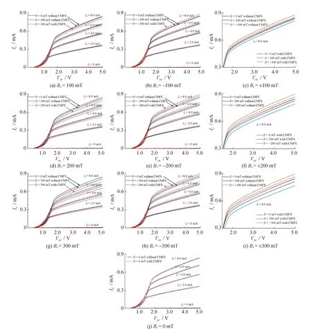
Fig.5 Ic-Vce characteristic curves of SMST with and without CMFS under different Ib
As shown in Fig.6, the base injection currentIbis increased from 0 mA to 8.0 mA (with a step of 2.0 mA) under a constantVceof 5.0 V. Fig.6(a)~Fig.6(c) show theIc-Ibcharacteristic curves of the SMST with and without the CMFS whenBx=±100 mT, ±200 mT and ±300 mT, respectively.

Fig.6 Ic-Ib characteristic curves of SMST with and without CMFS under different Bx
The experimental results indicate the SMST simultaneously exhibits positive and negative magnetic sensitive properties without effect of the CMFS onIcwhenBx=0 mT. The CMFS has a little coercive force, small remanence and no its own magnetic field, resulting in that the SMST can’t be acted under no other magnetic field. As shown in Fig.5(a)~Fig.5(c), theIc-Vcecharacteristics of the SMST can be changed under the magnetic field. Furthermore, theIc-Vcecharacteristics with the CMFS significantly change compared with that without the one, with an increasing variation ofIcwithIbwhenBx=±100 mT, especially existing a maximum enhancingIcwhenIb=8.0 mA. As shown in Fig.5(d)~Fig.5(f), theIc-Vcecurve changes for the SMST atBx=±200 mT are even more significant than that atBx=±100 mT. Even though theIc-Vcecharacteristics of the SMST with the CMFS increases with respect to that without the one, the enhancing degree decreases. WhenBx=±300 mT, theIc-Vcecharacteristics of the SMST with the one achieve a maximum increase than that without the one. From the above experiment results, it can be included that theIc-Vcecharacteristics enhance with the increasing magnetic field.
The enhancing degree ofIc-Vcecharacteristics of the SMST with the CMFS decreases as the increasing magnetic field. From Fig.6, it can be found thatIcincreases withIb, obtaining a maxIcwhenIb=8.0 mA. When exerting an external magnetic field to the SMST,Icexhibits not only a positive but also a negative magnetic sensitive property, with an increasing change ofIcwith the increasingBx. Furthermore, the changes ofIcfor the SMST with the CMFS represents a great increase but decreasing as the increasingBx.
3.2 Vout-B Characteristics
Due to the changes ofIcof the SMST with the CMFS decrease as the increasing magnetic field, the saturation magnetization of the CMFS was investigated before packaging it with the SMST. The hysteresis loops of the CMFS samples were measured by the vibrating sample magnetometer (VSM). The test results are shown in Fig.7(a), whereHis the magnetic field strength andMis the magnetization intensity. Based on the typical properties of soft magnetic materials for the CMFS of Ni-Fe, the coercive force (Hc) and saturation magnetization (Ms) are obtained. To study the characteristics of collecting magnetic field for the CMFS, the relationship curves of the output voltage (Vout) and magnetic induction intensity (Bx) were measured using a magnetic field generator system and a semiconducting characterization system in the conditions ofBxin the range from -300 mT to 300 mT, supplly voltageVDD=5.0 V, the collector load resistanceRL=2.3 kΩ and the base injection currentIb=8.0 mA. TheVout-Bcharacteristic curves of the SMST with different CMFS made up of different soft magnetic materials are shown in Fig.7(b), in which the black, red and blue lines refer as 1J36-Ni-Fe, 1J50-Ni-Fe and 1J85-Ni-Fe, respectively.
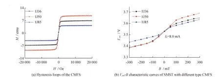
Fig.7 Hysteresis loops of the CMFS and the Vout-B characteristic curves of SMST with CMFS
From the results of hysteresis loops andVout-Bcharacteristic curves, it indicates that all type soft magnetic materials have the excellent properties, including a high permeability, low coercive force and a low remanence. As is shown in Fig.7(a), theMsof 1J50 is better than that of 1J36 and 1J85. All outputVoutof the SMST with different CMFS increase withBx, owning a linear region with a higher slope as shown in Fig.7(b). Due to the liner region under a lower slope has a high magnetic field over theMsof each CMFS, it means that the CMFS composed of 1J50 achieves a longest liner region with a highest slope in accordance with the result of hysteresis loops. Based on the above analysis, the material and the linear working region can be determined,i.e. material of 1J50 and the magnertic field range from -80 mT to 80 mT.
To study the characteristics of the collecting magnetic field for the CMFS, the relationship curves ofVoutandBxwere got using a magnetic field generator system and a semiconducting characterization system. The range ofBxis from -80 mT to 80 mT, the supplly voltageVDD=5.0 V and the collector loadRL=2.3 kΩ,Ibis 2.0 mA, 4.0 mA, 6.0 mA and 8.0 mA, respectively. Fig.8(a) shows the test circuit diagram, whereIbcan be changed by adjusting the base load resistance (Rb). As shown theVout-Bcharacteristic curves in Fig.8(b), it can be seen thatVoutincreases with the magnetic field at a constantIb, linearly, in contrast existing an enhanced magnetic sensitivity of the SMST as the increasingIb. Fig.8(c) shows the basicVout-Bcharacteristic curves of the SMST with and without the CMFS whenIb=8.0 mA. Based on that, it indicates that the magnetic sensitivity of the SMST with the CMFS can achieve a great growth rate than that without the one, where the magnetic sensitivity increases with the increasingLmof the CMFS but with a reduced increment. WhenLm3=6.0 mm, the magnetic sensitivity is up to a maximum.

Fig.8 Test circuit diagram and Vout-B characteristic curves of SMST with and without CMFS
WhenVDD= 5.0 V,RL= 2.3 kΩ,Ib=8.0 mA and T = 293 K, the characteristic parameters of the proposed SMST without and with different types of CMFS were given in Table 1.

Table 1 Characteristic parameters of SMST with and without CMFS.
From the data of Table 1, it can be found that the characteristic parameters of the SMST have been improved, significantly. The magnetic sensitivity of the proposed SMST with the CMFS increases with the increasing lengthLm, achieving all gains more than 2.4 times magnification than that without the one at eachLmand owning the amplification trend similar to the simulation result. WhenLm3=6.0 mm, the proposed sensor compared to that without the CMFS realized super properties, i.e. a maximum magnetic sensitivity of 926.1 mV/T and a maximum magnification of 3.5 times. Due to the existing of the void between the SMST and the CMFS, the actual experiment enhancing factor is smaller than the simulation result.
4 Conclusions
A magnetic field sensor is designed and fabricated on a p-type silicon wafer with a high resistivity utilizing microelectromechanical system (MEMS) technology, consisting of a SMST and two CMFSs fabricated based on Ni-Fe alloy material by using wire cut electrical discharge machining (WEDM) technology. Through analyzing the properties of the CMFS based on finite element software ANSYS, the sensor structure was optimized by adjusting the dimensions and the angles. The experimental results show that it is possible for the CMFS to improve the sensitivity of the SMST by collecting and guiding magnetic flux to its sensitive region. WhenT= 293 K,VDD= 5.0 V andRL= 2.3 kΩ, the resulted SMST with the CMFSs represents an excellent sensitivity of 926.1 mV/T about 3.5 times than that without the one in a magnetic field range from -80 mT to +80 mT at room temperature. The study on the silicon magnetic sensitive transistor with the collecting magnetic field structure makes great contribution to the measurement of magnetic field and improvement of testing accuracy.
杂志排行

黑龙江大学工程学报的其它文章
- Research and discussion on road extraction with deep learning network U-Net
- 中国城市更新体系中的工业遗产再生研究
——以合肥市东部新中心核心区为例 - Preparation and electrochemical properties of modified PAN-based carbon fiber electrode materials with Nickel-plated polystyrene spheres
- 环戊二烯基锕系配合物结构和还原性质的密度泛函理论研究
- 王花泡滞洪区洪水资源优化分析
- LamAg (m=1-4) 小团簇的结构和稳定性密度泛函研究