液力减速器启动过程的瞬态压力脉动分析
2020-03-03刘厚林张立新刘嘉伟
刘厚林,张立新,董 亮,刘嘉伟
液力减速器启动过程的瞬态压力脉动分析
刘厚林,张立新,董 亮※,刘嘉伟
(江苏大学流体机械工程技术研究中心,镇江 212013)
为研究叶片倾角、充液率对液力减速器启动过程瞬态压力脉动的影响,该文基于INV3020数据采集系统组成的瞬态压力脉动测试系统,对60°、75°、90°共3种叶片倾角和60%、70%、80%、90%、100%共5种充液率工况下的压力脉动信号进行采集。结果表明:不同叶片倾角的液力减速器在启动过程压力脉动峰值所对应的频率均出现在200 Hz以下,压力脉动主要集中于叶频处且随着叶片倾角的增加呈现增大的趋势。不同充液率液力减速器在启动过程压力脉动主要集中于叶频处,在60%~90%充液率工况下,压力脉动幅值随着充液率上升而减小,在90%~100%充液率工况下,随着充液率上升而快速增大。因此,减小叶片倾角和维持充液率在70%~90%下能有效减小压力脉动。研究结果揭示了不同叶片倾角,不同充液率对液力减速器启动瞬态压力脉动的影响规律,可为低振动,低噪声液力减速器的优化设计提供理论依据。
压力;模型;液力减速器;充液率;叶片倾角;瞬态
0 引 言
液力减速器也称液力缓速器,是车辆传动系统中一种高效辅助制动装置[1-3]。目前,车辆正向高速、重载方向发展,但车辆制动仍主要依靠传统摩擦制动器来实现,车辆在制动过程中会出现制动器制动效能热衰退现象,导致车辆安全性和舒适性下降[4-7]。相比传统车辆制动系统,装有液力减速器的车辆能有效改善制动和传动品质,在长坡道下行时,能够连续提供控制车辆下行速度的阻力,保证行车安全;在平路制动时,能够平稳、无磨损地提供车辆所需约90%的制动力,且在整个制动过程中,速度均匀变化,避免出现冲击现象[8-9]。在国外,液力减速器已经广泛应用于军用车辆,重型工程汽车和大型公共汽车上;在国内,虽然一些厂家也开始研制相应的产品,但是品种比较单一,还未能广泛应用。因此,提升自主研制液力减速器的能力,对中国车辆行车安全、经济发展具有重大意义。
液力减速器内部流动复杂,在启动工况时泵轮、涡轮较大的转速差会引起明显的非定常流动现象,由于液力减速器的内部流动决定外部性能,所以内部的压力脉动是影响机组运行稳定性的关键因素[10-11]。目前,国外学者在液力变矩器的概述理论、流场特性和稳态试验测量方面已经做了大量的研究[12-15]。国内对液力变矩器的研究主要集中在稳态特性试验和理论分析[16-18];国外对液力变矩器流场计算方法的研究逐渐由稳态发展到瞬态。以稳态特性工作理论解释液力元件在实际动态下的工况变化,在以传动为主的液力元件应用领域是合适的,但在以快速性、准确性等瞬态指标为目标的控制系统中应用液力元件,则必须考虑它们的动态特性[19]。实际工作过程中,液力减速器经常处于速度突变的瞬态变化过程,所以液力减速器内部流体的非线性瞬态特性不能忽略[20-22]。
Song等[23]采用全流道瞬态数值计算方法对液力减速器瞬态流场进行分析与计算,开发了液力减速器流场分析、性能计算与优化设计相结合的液力减速器设计优化系统。刘春宝[24]等在液力变矩器瞬态流场特性分析的基础上进行了液力变矩器三维瞬态流场计算,建立了旋转坐标系下的控制方程,采用数值模拟的方法对液力变矩器瞬态控制方程进行计算,并将计算结果与试验结果对比,二者误差较小,说明瞬态流场计算方法可用于指导液力变矩器的设计和性能优化。
液力减速器内部压力脉动是引起其振动噪声的重要因素之一,目前还没有液力减速器在不同叶片倾角、不同充液率下启动过程瞬态压力脉动的研究。本文以液力减速器为试验对象,采集不同叶片倾角在不同充液率下启动过程的瞬态压力脉动信号,分析轴频和叶频处的压力脉动幅值,研究叶片倾角和充液率对瞬态压力脉动的影响,以期为低振动低噪声液力减速器的结构优化设计提供理论依据。
1 试验对象与测量系统
1.1 试验对象
本文以液力减速器为试验对象,其水力结构主要包括泵轮、涡轮、壳体和后盖板,液力减速器结构如图1所示。

1.泵轮 2.涡轮 3.壳体 4.后盖板 5.机械密封 6.传动轴 7.轴承箱 8.轴承 9.地脚螺栓
泵轮与涡轮叶片倾角相同,倾角分别为60°、75°和90°,循环圆内径为50 mm,外径为150 mm,叶片高度均为20 mm,泵轮叶片数为11片、涡轮叶片数为12片。泵轮、涡轮几何参数如表1所示。
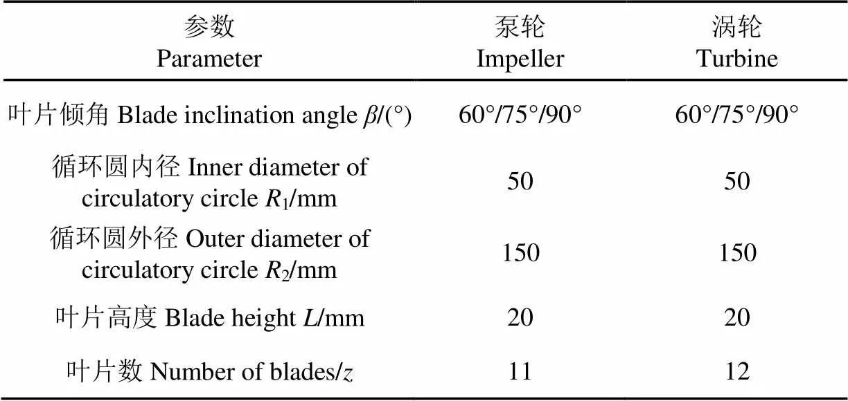
表1 泵轮、涡轮几何参数
1.2 试验方案
以60°、75°、90°叶片倾角的液力减速器为试验对象,调节腔体内充液量,对60%、70%、80%、90%、100%充液量,700、800、900、1 000 r/min时的液力减速器进行压力脉动信号采集。
1.3 试验测量系统
试验装置主要有变频器、驱动电机、液力减速器、高频动态压力传感器、转矩转速采集仪和增压泵等。变频器型号为三星F700变频器,可实现对驱动电机变频调速。驱动电机为皖南生产的三相异步电动机,型号为Y2-90L-4,技术参数如表2所示,试验系统示意图如图2所示。

表2 电机参数

1.变频器 2.INV3020C数据采集系统 3.转速转矩采集仪 4.电机 5.转速转矩传感器 6.出口球阀 7.压力脉动传感器 8.进口球阀 9.液力减速器 10.排液球阀 11.增压泵 12.水池
测试前,打开液力减速器进口球阀和出口球阀,启动增压泵将液力减速器腔体充满水,关闭增压泵,关闭液力减速器进口球阀和出口球阀,通过调节排液球阀开度来控制液力减速器腔体不同充液率[25]。
充液率(%)的计算公式为
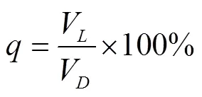
式中V为充液容积,mm3;V为满充液时的充液容积,mm3。
充液率的标定如图3所示。
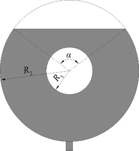
注:α为充液角,(°)。
充液容积V的计算公式为
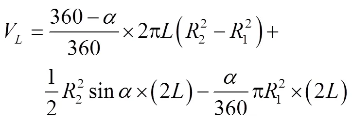
满充液时的充液容积V的计算公式为

本文对不同工况下液力减速器启动过程瞬态压力脉动信号进行采集和数据处理。试验采用HM90高频动态压力传感器采集压力脉动信号,每次测量之前对压力传感器均进行校准。HM90高频动态压力传感器技术指标如表3所示,压力脉动测点布置位置如图4所示。

表3 HM90高频动态压力脉动传感器参数
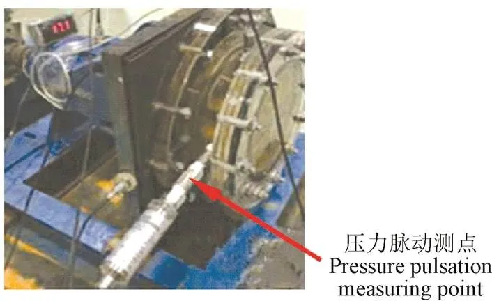
图4 高频动态压力变送器安装位置
采样频率过高会导致特征信号混叠,采样频率过低则会导致特征信号无法被捕捉,无法保证采集信号对原始信号的真实还原。为反映真实瞬态压力脉动信号,根据奈奎斯特理论,将采样频率设为高于原始信号最高频率的2倍[26]。本文选取采样频率为6 400 Hz,采样时间为30 s。
2 试验结果与分析
2.1 液力减速器瞬态压力脉动模型
压力脉动是由于叶片和导叶之间相互作用引起的周期性水流脉动。液力减速器内部压力脉动产生原因是:转动的泵轮叶片与静止的涡轮叶片之间产生动静干涉作用,泵轮叶片出口的旋转压力场、速度场与下游的静止的涡轮叶片发生干涉,从而导致压力脉动[27-28]。下面从液力减速器压力脉动的产生机理进行研究。
假定液力减速器内部流体绝热、不可压缩,内部能量转换主要有2种形式,泵轮将自身的动能转换为流体的动能,流体将获得的动能全部转换为内能,因此可以用连续性方程和动量方程作为控制方程。旋转坐标系下的控制方程如下[29]:
1)连续性方程

2)动量方程


假定泵轮内部为定常流动,同时忽略泵轮内部的质量力,方程可以简化为

将式(7)转化为圆柱坐标系下表示为
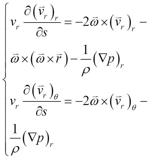
泵轮周围流场表示为


2.2 压力脉动信号分析
2.2.1 不同叶片倾角对压力脉动的影响
对试验数据的压力脉动时域进行时频变换,本文采样频率为6 400 Hz,样本点32 768个,采用汉宁窗进行数据处理[30]。选取充液率70%下的各倾角叶轮时域信号内连续数点做汉宁窗的快速傅里叶变换,图5为不同角度叶轮在70%充液率下启动至转速分别达到800、900、1 000 r/min的瞬态过程压力脉动频域图,试验结果如图5所示。本文下面所说轴频、叶频、干涉频率都是针对于目标转速而言。

图5 不同叶片倾角在70%充液率下的压力脉动频域图
从图5可以看出,各角度叶轮的压力脉动峰值所对应的频率均出现在200 Hz以下,启动过程压力脉动峰值点出现在叶频处,这是由于液力减速器启动瞬间转速的快速增加导致了干涉频率。90°叶轮的压力脉动峰值最大,且压力脉动主要集中于轴频、干涉频率及其倍频处。75°叶轮和60°叶轮与90°叶轮有相似的规律,在干涉频率处压力脉动幅值最大,且干涉频率处压力脉动幅值随着叶频倍数的增加呈现下降趋势。压力脉动由泵轮与涡轮干涉产生,且表现为干涉频率倍频脉动。为进一步分析不同倾角叶轮对压力脉动的影响,取轴频、干涉频率及其倍频处的压力脉动幅值,得到了不同倾角叶轮在70%充液率情况下启动到不同转速情况下轴频、干涉频率压力脉动幅值如表4所示。
从表4中可以看出,在轴频处,压力脉动幅值表现为随着叶轮角度的增大先减小后增加的变化趋势。瞬态过程中压力脉动主要集中于叶频处,在充液率70%情况下,较低转速即700、800 r/min时,压力脉动幅值随着叶轮角度增大而上升;较高转速时,压力脉动幅值随着叶轮角度增大先减小后大幅度上升。在90°叶轮达到峰值1 670 Pa。在叶频倍频处,叶片倾角的增加也引起压力脉动幅值的增大。因此,减小叶片倾角角度能有效的降低压力脉动幅值,从而降低动静叶片干涉产生的射流尾迹影响。

表4 70%充液率下不同叶片倾角的压力脉动幅值
2.2.2 不同充液率对压力脉动的影响
截取75°叶轮下的各充液率在不同转速时域信号内连续数点做汉宁窗的快速傅里叶变换,分析频域0~1 000 Hz内主要频率成分及其幅值大小,如图6所示。

图6 启动至不同转速的压力脉动频域图
从图6可以得出,瞬态过程下,压力脉动主要集中在0~400 Hz。随着充液率的增加,压力脉动幅值先减小后增大,在100%充液率时液体所具有的动能达到最大,此时叶频处压力脉动为最高值。压力脉动峰值存在于轴频、叶频及叶频倍频处。不同充液率下的轴频、叶频及叶频倍频处压力脉动见图7。
由图7中可以看出,在轴频处,随着充液率增大,压力脉动幅值总体呈现上升趋势,在60%~80%充液量时,压力脉动幅值随转速变化不明显;在90%~100%充液率时,随着泵轮转速的增加,压力脉动幅值明显增大;相同充液量下,压力脉动幅值随转速增大而增加。压力脉动最大值在叶轮叶频处,且随着充液率增加压力脉动先降低后增加;随着转速的增加,各充液率下压力脉动幅值变化幅度越大,所以适当降低转速可以减小压力脉动变化幅度,增加液力减速器使用寿命。在叶轮倍频处,压力脉动幅值在60%~90%充液率时下降,在90%~100%充液率时大幅度上升且达到最大值。因此,在75°叶轮时,使充液率保持70%~90%能有效减小压力脉动。
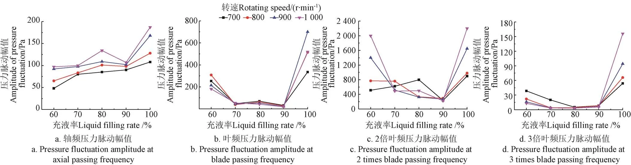
图7 不同充液率压力脉动幅值折线图
3 结 论
1)在瞬态启动过程时,液力减速器运行时的压力脉动峰值出现在一倍叶频处。
2)对于相同充液率下不同叶片倾角的叶轮,倾角在60°~75°时,启动过程压力脉动峰值随着转速的增加呈现减小的趋势;倾角在75°~90°时,启动过程压力脉动峰值随着转速的增加呈现先减小后快速增大的趋势。在实际工程应用中,保持叶片倾角在60°~75°时可以有效降低瞬态压力脉动。
3)75°叶轮在60%及100%充液率启动过程有较大的压力脉动,在70%~90%充液率下压力脉动较小,且压力脉动幅值随转速增大变化不大。在实际工程应用中,保持充液率在70%~90%时可以有效降低瞬态压力脉动,实现液力减速器平稳启动。
[1]梁荣亮,过学迅. 车辆液力减速器的应用现状与技术发展[J]. 上海汽车,2008(2):28-31.
[2]吴超,徐鸣,李慧渊,等. 车辆液力缓速器的特点分析及发展趋势[J]. 车辆与动力技术,2011(1):51-55.
Wu Chao, Xu Ming, Li Huiyuan, et al. Analysis of characteristic and development of vehicle hydraulic retarder[J]. Vehicle & Power Technology, 2011(1): 51-55. (in Chinese with English abstract)
[3]荆崇波,胡纪滨,鲁毅飞,等. 车用液力减速器制动性能试验研究[J]. 汽车技术,2005(12):27-31.
Jing Chongbo, Hu Jibin, Lu Yifei, et al. Study on brake performance of automotive hydraulic retarders[J]. Automobile Technology, 2005(12): 27-31. (in Chinese with English abstract)
[4]王峰,阎清东,乔建刚. 液力减速器制动性能的计算方法[J]. 起重运输机械,2006(5):24-27.
[5]闫清东,邹波,魏巍. 液力减速器部分充液工况制动性能计算方法研究[J]. 北京理工大学学报,2011,31(12):1396-1400.
Yan Qingdong, Zou Bo, Wei Wei. Research on braking performance calculation model of two-phase flow in hydraulic retarder cascade[J]. Transactions of Beijing Institute of Technology, 2011, 31(12): 1396-1400. (in Chinese with English abstract)
[6]闫清东,邹波,唐正华,等. 车用液力减速器叶片数三维集成优化[J]. 农业机械学报,2012,43(2):21-25.
Yan Qingdong, Zou Bo, Tang Zhenghua, et al. 3D Integrated optimization of blade numbers for vehicular hydraulic retarder[J]. Transactions of the Chinese Society for Agricultural Machinery, 2012, 43(2): 21-25. (in Chinese with English abstract)
[7]陆中华,程秀生. 重型车液力缓速器制动性能仿真研究[J]. 汽车技术,2009(3):22-24.
Lu Zhonghua, Cheng Xiusheng. Simulation study on the brake performance of heavy-duty vehicle hydraulic retarder[J]. Automobile Technology, 2009(3): 22-24. (in Chinese with English abstract)
[8]杨珊珊. 汽车液力减速器结构参数优化与动态特性预测[D]. 长春:吉林大学,2011.
Yang Shanshan. Structural Parameter Optimization and Dynamic Characteristics Prediction of Automotive Hydrodynamic Retarders[D]. Changchun: Jilin University, 2011. (in Chinese with English abstract)
[9]马文星,刘春宝,雷雨龙,等. 工程机械液力变矩器现代设计方法及应用[J]. 液压气动与密封,2012,32(10):71-76.
Ma Wenxing, Liu Chunbao, Lei Yulong, et al. Modern design methods and application of engineering machinery torque converter[J]. Hydraulics Pneumatics & Seals, 2012, 32(10): 71-76. (in Chinese with English abstract)
[10]闫清东,刘博深,魏巍. 液力变矩器流体-固体耦合压力脉动分析[J]. 兵工学报,2016,37(4):577-583.
Yan Qingdong, Liu Boshen, Wei Wei. Pressure load fluctuation analysis of torque converter based on fluid tructure interaction[J]. Acta Armamentarii, 2016, 37(4) :577-583. (in Chinese with English abstract)
[11]冯宜彬. 基于CFD分析的液力减速器设计研究[D]. 武汉:武汉理工大学,2008.
Feng Yibin. Research on the Design of Hydrodynamic Retarder[D]. Wuhan: Wuhan University of Technology, 2008. (in Chinese with English abstract)
[12]Yang S, Shin S, Bae I, et al. A Computer-integrated design strategy for torque converters using virtual modeling and computational flow analysis taekyung lee[J]. International Journal of Obesity, 1999, 36(9): 1252-1255.
[13]Shin S, Kim K J, Kim D J, et al. The effect of reactor Blade geometry on the performance of an automotive torque converter[M].DOI:10.4271/2002-01-0885.
[14]Kowalski D, Anderson C, Blough J. Cavitation prediction in automotive torque converters[C]//SAE 2005 Noise and Vibration Conference and Exhibition. 2005: 135-141.
[15]Robinette D L. Detecting and Predicting the Onset of Cavitation in Automotive Torque Converters[D]. Michigan: Michigan Technological University, 2007.
[16]何延东,马文星,邓洪超,等. 基于CFD的调速型液力耦合器设计方法[J]. 农业机械学报,2010,41(6):31-36.
He Yandong, Ma Wenxing, Deng Hongchao, et al. Design method of variable speed hydraulic coupler based on CFD[J]. Transactions of the Chinese Society for Agricultural Machinery, 2010, 41(6): 31-36. (in Chinese with English abstract)
[17]康灿,张贵峰,李利婷. 直叶片液力减速器内部流场及空化性能研究[J]. 机械设计与制造,2016(11):92-96.
Kang Can, Zhang Guifeng, Li Liting. Internal flows and cavitation performance of a hydraulic retarder equipped with straight blades[J]. Machinery Design & Manufacture, 2016(11): 92-96. (in Chinese with English abstract)
[18]董亮,肖佳伟,明加意,等. 液力减速器模型空化特性数值模拟及试验研究[J]. 排灌机械工程学报,2017,35(1):1-5.
Dong Liang, Xiao Jiawei, Ming Jiayi, et al. Numerical simulation and experimental study on cavitation behavior of hydraulic retarder model[J]. Journal of Drainage and Irrigation Machinery Engineering, 2017, 35(1): 1-5. (in Chinese with English abstract)
[19]孙善兵. 液力变矩器三维瞬态流场分析研究及改型设计[D]. 兰州:兰州理工大学,2012.
Sun Shanbing. 3D Ttransient Analysis of Internal Flow Field of Hydrodynanmic Torque Converter and Retrofit Design[D]. Lanzhou: Lanzhou University of Technology, 2012. (in Chinese with English abstract)
[20]Li Xusong, Cheng Xiusheng, Miao Liying. Numeical analysis on internal flow field of a hydraulic retarder[C]//Proceedings of the 2009 IEEE. International Conference on Mechatronics and Automation, Changchun, China: 2009: 3710-3715.
[21]张高峰. 液力变矩器瞬态特性的实验研究[D]. 上海:上海交通大学,2012.
Zhang Gaofeng. Test Investigation of Torque Converter Transient Performance[D]. Shanghai: Shanghai Jiao Tong University, 2012. (in Chinese with English abstract)
[22]闫清东,邹波,魏巍,等. 液力减速器充液过程瞬态特性三维数值模拟[J]. 农业机械学报,2012,43(1):12-17.
Yan Qingdong, Zou Bo, Wei Wei, et al.Numerical investigation on transient oil-filling process of hydraulic retarder[J].Transactions of The Chinese Society of Agricultural Machinery, 2012, 43(1): 12-17. (in Chinese with English abstract)
[23]Song K, Kim K, Park J I, et al. Development of the integrated process for torque converter design and analysis[J]. Nucleic Acids Research, 2008, 18(1): 767-770.
[24]刘春宝,马文星,朱喜林. 液力变矩器三维瞬态流场计算[J]. 机械工程学报,2010,46(14):161-166.
Liu Chunbao, Ma Wenxing, Zhu Xilin. 3D Transient calculation of internal flow field for hydrodynamic torque converter[J]. Journal of Mechanical Engineering, 2010, 46(14): 161-166. (in Chinese with English abstract)
[25]李丹,杨耀东. 液力缓速器液压控制系统设计[J]. 机床与液压,2019,47(7):114-116.
Li Dan, Yang Yaodong. Design of hydraulic control system of hydraulic retarder[J]. Machine of Hydraulics, 2019, 47(7): 114-116. (in Chinese with English abstract)
[26]肖佳伟. 液力减速器空化特性试验及分析[D]. 镇江:江苏大学,2016.
Xiao Jiawei. Experimental Investigation and Analysis on Cavitation of Hydraulic Retarder[D]. Zhenjiang, Jiangsu University, 2016. (in Chinese with English abstract)
[27]季磊磊,李伟,施卫东,等. 叶片数对混流泵内部非定常压力脉动特性的影响[J]. 排灌机械工程学报,2017,35(8):666-673.
Ji Leilei, Li Wei, Shi Weidong, et al. Influence of different blade numbers on unsteady pressure pulsations of internal flow field in mixed flow pump[J]. Journal of Drainage and Irrigation Machinery Engineering, 2017, 35(8): 666-673. (in Chinese with English abstract)
[28]张兴,张文明,廖姣. 叶片数对低比转速离心泵性能影响分析[J]. 热能动力工程,2017,32(8):107-110.
Zhang Xing, Zhang Wenming, Liao Jiao. Impact of blade number on the performance of low specific speed centrifugal pump[J]. Journal of Engineering for Thermal Energy and Power, 2017, 32(8): 107-110. (in Chinese with English abstract)
[29]蒋跃. 隔舌对双蜗壳泵径向力和压力脉动影响的数值模拟研究[D]. 兰州:兰州理工大学,2013.
Jiang Yue. Numerical Simulation on Radial Hydraulic Forces and Pressure Fluctuations in Double Volute Pump with Tongue[D]. Lanzhou: Lanzhou University of Technology, 2013. (in Chinese with English abstract)
[30]董亮,赵宇琪,肖佳伟,等. 液力减速器空化前后振动及噪声特性变化机理[J]. 农业工程学报,2017,33(14):56-62.
Dong Liang, Zhao Yuqi, Xiao Jiawei, et al. Change mechanism of vibration and noise characteristics before and after cavitation in hydraulic retarder[J]. Transactions of the Chinese Society of Agricultural Engineering(Transactions of the CSAE), 2017, 33(14): 56-62. (in Chinese with English abstract)
Analysis of transient pressure pulsation during hydraulic retarder starting process
Liu Houlin, Zhang Lixin, Dong Liang※, Liu Jiawei
(,,212013,)
Hydraulic retarder is a highly efficient auxiliary brake device in vehicle transmission system. Compared with traditional vehicle braking systems, it can improve braking and transmission thereby improving safety in driving. Being able to independently design and manufacture hydraulic retarders is therefore essential to safeguarding development of vehicle industry for a country. The internal pressure pulsation in the hydraulic retarder is one of important factors that could cause vibrations and noise in a vehicle, while there is limited study on how the transient pressure pulsation changes responsively to the impeller angle and liquid filling rate in the transmission system. The purpose of this paper is to bridge this gap by presenting the results of an experiment study on the impact of the impeller angle and charging rate on transient pressure pulsation in a hydraulic retarder during its starting process. We compared three blade inclination angles: 60°, 75° and 90°, and five liquid filling rate: 60%, 70%, 80%, 90% and 100%, and conducted the experiments in a transient pressure pulsation test system equipped with an INV3020 data acquisition system. The test system included a frequency converter, a drive motor, a hydraulic retarder, a high frequency dynamic pressure sensor, a torque speed collector and a booster pump. During the test, the motor speed was adjusted by the inverter, and the liquid filling rate was adjusted by the inlet ball valve and the outlet ball valve in the hydraulic reducer as well as the booster pump to control water-filling of the hydraulic reducer cavity. The amplitude of the pressure pulsation at the axial frequency and the leaf frequency was analyzed to elucidate the effect of the impeller angle and the liquid filling rate. The results showed that the peaks of the pressure pulsation in the hydraulic retarder under different blade inclination angles occurred below 200 Hz, and the pressure pulsation mainly occurred at the leaf frequency and increased with the blade inclination. The pressure pulsation under different liquid filling rate mainly occurred at the leaf frequency. The amplitude of the pressure pulsation decreased as the charging rate increased from 60% to 90%, and then increased steadily when the charging rate further increased from 90% to 100%. Reducing the impeller angle and maintaining the charging rate at 70%-90% can therefore effectively reduce the pressure pulsation. The results presented in this paper unravel the impact of the impeller angle and charging rate on transient pressure pulsation in the hydraulic retarder, and have important implications for optimal design of low-vibration and low-noisy hydraulic retarders.
pressure; models; hydraulic retarder; liquid filling rate; blade inclination angles; transient
刘厚林,张立新,董 亮,刘嘉伟. 液力减速器启动过程的瞬态压力脉动分析[J]. 农业工程学报,2020,36(1):67-73.doi:10.11975/j.issn.1002-6819.2020.01.008 http://www.tcsae.org
Liu Houlin, Zhang Lixin, Dong Liang, Liu Jiawei. Analysis of transient pressure pulsation during hydraulic retarder starting process[J]. Transactions of the Chinese Society of Agricultural Engineering (Transactions of the CSAE), 2020, 36(1): 67-73. (in Chinese with English abstract) doi:10.11975/j.issn.1002-6819.2020.01.008 http://www.tcsae.org
2019-09-16
2019-12-19
国家自然科学基金(51879122,51779106);江苏省产学研联合创新资金(BY2016072-01);江苏省“六大人才高峰”高层次人才项目(GBZB-017);镇江市重点研发计划(GY2017001,GY2018025);江苏大学高级人才科研启动基金(15JDG052);江苏高校优势学科建设工程(PAPD)
刘厚林,研究员,主要研究方向为现代泵水力设计与优化方法。Email:liuhoulin@ujs.edu.cn
董 亮,副研究员,主要研究方向为旋转机械设计与优化。Email:dongliang@ujs.edu.cn
10.11975/j.issn.1002-6819.2020.01.008
TH132.46
A
1002-6819(2020)-01-0067-07
