Study on liquid-filled structure target with shaped charge vertical penetration
2020-01-07MinGuoXudongZuXiojunShenZhengxingHung
Min Guo ,Xu-dong Zu ,Xio-jun Shen ,Zheng-xing Hung
a School of Mechanical Engineering,Nanjing University of Science and Technology,Xiaolingwei 200,Nanjing 210094,China
b Unit 63961,Peoples Liberation Army,6th Beiyuan Road,Chaoyang Beijing,100012,China
ABSTRACT Based on the characteristic expanded hole of a shaped charge jet(SCJ)for target penetration and the reflow characteristics of liquids,the liquid-filled structure of a target disturbs the stability of the SCJ acquired in two independent parts.The interference jet speed interval,the escape jet speed interval,and the surplus depth are calculated on the basis of the virtual origin theory.The experimental results,including the velocity of the escaped jet tip and the surplus depth of penetration,are consistent with the theoretical results.Experiments show that the theory can describe the interaction process of the target with a shaped charge jet.
Keywords:Shaped charge Liquid-filled structure target Disturbed jet Escape jet
1. Introduction
Armour for tanks must improve their protective ability to keep crews and important facilities safe inside them.Increasing the hardness and thickness of steel armour outside tanks is not enough to meet the protection requirement.Therefore,most tank vehicles are fitted with additional armour.The new kind of additional armour is light,and it has high cost-effectiveness and low collateral damage. Explosive reactive armour (ERA), ceramic composite,space,and grating armours are widely used in tanks.ERA and ceramic composite armour can be used as additional main armour.ERA can protect vehicles from damage through its shaped charge and kinetic warheads.However,fly-plates caused by ERA explosive may harm the soldiers or equipment items.The shock wave produced by ERA explosive can injure the crew and the important facilities inside the vehicle.Ceramic composite armour can resist the attraction of a kinetic warhead but cannot effectively resist a shaped charge warhead.
Liquid-filled structure armour is a new kind of additional armour.It is made of bulk steel with a drilled matrix of blind holes that can be linked by small channels.Liquid(e.g.,water and diesel)can be injected in the holes,and a steel cover plate seals the liquid with seal rings and bolts.Liquid-filled structure armour can effectively resist a shaped charge warhead and can reduce the weight of additional armour.The liquid can be used for another purpose if necessary.Few studies have been conducted on the mechanism of liquid-filled structure armour with a SCJ.J.J.White[1]investigated the penetration of a jet in a liquid-filled hermetic structure and found that liquids can undermine jet stability.E.S.Lee[2]explored the penetration process of jet particles in water through high-speed photography and X-ray experiments.M.Held[3]modified Szendrei equations and obtained the reaming equations of jet penetration in water through high spatial and temporal resolution and profilestreak technology.On the basis of visual origin theory,Z.Y.Gao[4]established a mechanical model of a diesel oil-filled hermetic structure interfering with a jet,obtained the interfered velocity range expressions of the jet,and verified the theoretical model through an X-ray experiment.X.Zhang[5]considered that the spray of the liquid and the radial direct convergence in the diesel oil-filled hermetic structure made an SCJ unstable.The interaction characteristic of an SCJ penetrating such armour is studied in this research.The interaction process is analysed in detail.The liquidfilled structure of the target disturbs the stability of the SCJ acquired in two independent parts.We consider the effect of the reflow liquid reflected by the bottom steel plate,as well as the cylindrical walls of the holes,on the stability of an SCJ.The velocity intervals of the disturbed SCJ and the escaped SCJ are calculated.The depth of penetration of the escaped jet is calculated based on the virtual origin model and is consistent with the experimental results.The theoretical model in this paper is more accurate and appropriate than the model given in Refs.[4,5].
2. Interaction model of liquid-filled structure target with SCJ
2.1. Shaped charge
The φ 56 mm standard shaped charge(Fig.1)is observed in this research.The standard shaped charge weighs 180 g and stands at 93.3 mm.It has a 0.8 mm oxygen-free high-conductivity copper(OFHC)cone liner and JH-2 explosive with a density of 1.72 g/cm3.The standard shaped charge is detonated by a#8 detonator.The penetration of the standard shaped charge is not deep.Its structure is simple,and its depth of penetration(DOP)is stable,with a jerk value of the depth of no more than 3%.
In the experiment lot,the average DOP in#45 steel of the standard shaped charge under an 80 mm stand-off was 201 mm,i.e.,256 mm under the 254 mm stand-off.Q.Q.Xiao[6]revealed the detailed character of an SCJ from X-ray experiments.
2.2. Target
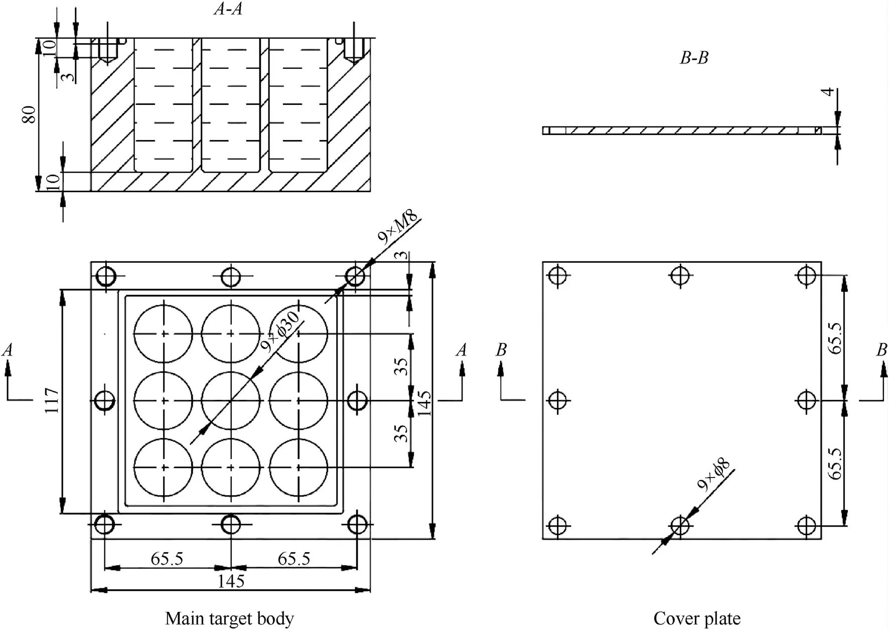
The liquid-filled target consists of the main target body,cover plate,seal ring,and bolts.The left part of Fig.2 shows the main target body,which is made of#45 medium carbon steel.The overall dimensions are 145 mm×145 mm×80 mm.Each of the nine blind holes is 30 mm in diameter and 70 mm in depth.The holes are arranged in a matrix and are processed with milling tools.The distance between two holes is 5 mm.A seal groove,which is 3 mm deep and 3 mm wide,is milled on the surface of the main target body around the holes.Three threaded holes are placed along each side of the seal groove.Water is injected into the holes.The seal ring is fitted in the seal groove,and the cover plate whose material is Q235 steel is screwed to the main target body to seal the target.The cover plate and the blinds holes form compartments.

Fig.1.φ 56 mm standard shaped charge.
2.3. Process of SCJ penetration of multi-hole-filled-liquid structure target
Fig.3 shows the process of SCJ penetration of the filled-liquid structure target.(1)The SCJ penetrates the liquid inside the compartments of the target.The shock wave is formed at the tip of the SCJ.The shock wave translates in the target,and the cavity area is formed due to the effect of the expanding hole of the jet in the liquid,which causes the liquid to compress.(2)The SCJ tip pierces the bottom steel plate of the main target body,and part of the SCJ escapes before it is disturbed by the reflow liquid which impacts the bottom plate under the shock wave then reflects by the reactive force of the bottom plate and reflected shock wave and make it cross the penetration path and disturbs the stability of the SCJ.(3)A part of SCJ's stability is disturbed by the reflow liquid which is reflected by the bottom steel plate and the reflect shock wave.This is the first part of disturbed SCJ.After that is a part of the escapes jet.(4)The tail part of the SCJ is disturbed by the reflow liquid which impacts the cylinder wall under the shock wave then reflects by the reactive force of the cylinder walls of the compartments and reflected shock wave and make it cross the penetration path and disturbs the stability of the SCJ.This is the second part of disturbed SCJ.(5)After the SCJ penetrates the liquid-filled structure target,two part of escaped jet can penetrate the witness target still.
2.4. Penetration model of SCJ
The SCJ will penetrate the liquid-filled structure target and the witness target.These two part are not continuous,so the theoretical model of the lateral drift velocity of the jet is suitable here.This theoretical indicates that the depth of penetration of the shaped charge jet changes with the stand-off distance.The drift velocity of the jet is

where vdis the drift velocity,ξ is a constant related to the material state and processing technology.tbis the break up time of the jet,dbis the diameter of the jet when it break up.
Assuming that the jet virtual origin coordinates are(,t),the jet is divided into finite segments with number n.Furthermore,the velocity of theithfinite segment is vji,and the stand-off distance isz0(from the virtual origin to the target).Thus,the time for the first jet finite segment reaches the witness target is

Let velocity gradient of the ith jet from head to tail as Δvji,the length of this jet finite segment at the timet0is

If the total depth of penetration isPi-1before the ith jet finite segment reaches the target,then the time for the jet finite segment to hit the target is expressed as

Based on the modified Bernoulli equation,the penetration velocity in the witness target of the ith finite segment can be written as

Fig.2.Structure of the target.

Fig.3.Schematic diagram of the penetration process.

The diameter of the hole created by the jet that penetrates the target[10]is


The penetration time for the ith jet finite segment is

The depth of penetration by this jet finite segment is

After the penetration process by the ith jet finite segment is finished,the total depth of penetration is

Based on the volume constant,the diameter of the ith jet finite segment can be obtained as

If the timetiof the ith jet finite segment is greater than the break up timetb,or if this jet finite segment is disturbed when it passes through the liquid-filled structure target,then the ith jet finite segment proceeds off the axis before it reaches the bottom of the penetration hole.There is

This jet finite segment is unable to reach the bottom of the penetration hole to penetrate the target effectively.Thus,
ΔPi=0
if

The finite segment does not exceed the bottom of the penetration hole.The depth of penetration is calculated using Eq.(9),and the total depth of penetration is calculated using Eq.(10).
2.5. Theoretical model of SCJ vertical penetration to liquid-filled structure target
When the SCJ penetrates the cover plate and bottom plate,the penetration process can be seen as steady-state penetration.When the SCJ penetrates the liquid in the structure,the penetration velocity is faster than the sound velocity of the liquid(in this study,we inject water in the holes)in the compartments.Thus a shock wave is formed from the tip of the SCJ and the cavity area is formed between the SCJ and the shock wave front.The pressure of liquid near the shock wave front in the same compartment with the SCJ will increase quickly under with the shock wave front moving,as shown in Fig.4.The interaction time is short.Consequently,we ignore the temperature conductivity in the liquid and its vaporisation.
When the SCJ penetrates the target,the liquid may be affected several times.Based on the research of Rosenberg and Dekel[9],the interval between two impacts can be obtained as

whereljtis the length of the SCJ when it penetrates the target,andCjis the sound velocity of the SCJ material.

Fig.4.Schematic diagram of shaped charge jet penetrating the bulkhead structure of the liquid composite target.
The density and temperature of the liquid increased after the shock wave front when the SCJ penetrates the liquid.Based on the research of Donson and Higginson[7],the relationship of ρland P can be written as

where ρlis the density of the liquid under pressureP,and ρl0is the density of the liquid in a conventional environment.
The liquid pressure during the penetration of the SCJ into the liquid can be calculated as

When the jet moves in the liquid,the half cone angle θ of the shock wave(Mach wave)can be obtained as

whereClis the sound velocity of the liquid,and vjis the velocity of the SCJ tip.
Under the pressure of the shock wave,the liquid moves along the normal direction of the shock wave front,as shown in Fig.5.
A liquid microelement is reflected when it affects the wall of the compartments.Given the interaction of a nearby material,a liquid microelement nearly moves back along the original direction.The reflectance is

Fig.5.Schematic diagram of water translating under shock wave.

where ρtandCtare the density and sound velocity,respectively,of the target body,and ρlandClare the corresponding values of the liquid.
The movement of the liquid microelement is mainly caused by the shock wave, and such movement is observed during the expansion of the liquid hole.The radius of the penetration hole[8]without restraint can be calculated as

whereRtis the hydrostatic pressure of the water.
The liquid is constrained in the compartments and cannot be sprayed outside before the SCJ penetrates the bottom of the main target body.Therefore,the liquid can only be compressed and can raise the density under high pressure.
After the SCJ penetrates the target,the liquid in the target sprays under high pressure.The liquid beside the penetration hole on the bottom plate can be continuously sprayed according to Bernoulli's equation

wherep1is the pressure in the penetration hole on the bottom plate,p2is the pressure out of the penetration hole on the bottom plate,v1is the average flow velocity of the liquid in the structure near the penetration hole on the bottom plate,andv2is the average flow velocity of the liquid out of the structure near the penetration hole on the bottom plate.
For the continuous quality equality of the two sides of the bottom plate,we write

whereA1andA2are the cross-sectional areas of the hole of the liquid-filled structure target and the penetration hole on the bottom plate,respectively.
The form of the bottom penetration hole is rounded when the SCJ vertically penetrates the target.Therefore,the area of flow inside and outside is written as

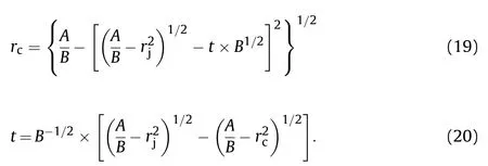
whereRandrctare the radii of the hole of the main target body and the penetration hole on the bottom steel plate,respectively.
Combining Eqs.(16)and(19),and(21)-(24),the spray velocity of the liquid can be calculated.
The volume of the sprayed liquid can be written as

where Δtis the time from the SCJ's penetration of the bottom plate until the second part reflow liquid starts to disturb the stability of the SCJ.
Through the whole process,the height of the liquid surface diminishes and can be obtained as

The SCJ will not be disturbed by the liquid-filled structure target between its piercing of the bottom plate and the start of collision with the SCJ of reflow liquid reflected by the bottom steel plate.
1)The first part of the liquid disturbs the stability of the SCJ.
The reflow liquid reflected by the bottom steel plate disturbs the stability of the part of the SCJ that is still inside the target.The disturbed jet is considered no longer has ability to penetrate.
Between the two part of the disturbed jet,the escaped jet can still penetrate the target as usual.
2)The second part of the liquid disturbs the stability of the SCJ.
The remaining SCJ is disturbed by the second part of the reflow liquid reflected by the cylinder walls of the compartments.The disturbed jet is considered no longer has ability to penetrate.
The escaped jet still has penetration ability.DOP can be calculated based on section 2.4.
3. Experiments and calculations
3.1. Experiments on standard shaped charge
For general research,the φ 56 mm standard shaped charge is adopted.The jet tip velocity is 6453 m/s,and that of the tail is 1179 m/s.The length of jet at 80 mm standoff equals 111.5 mm[6].
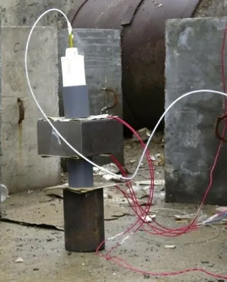
Fig.6 illustrates the DOP experiments of the standard shaped charge used in the study under standoff are measured 80 mm and 254 mm.To obtain the velocity of the SCJ tip,velocity sensors were set on both ends of the standoff cylinder.Table 1 presents the experimental results.

Fig.6.DOP experimental setup with sensors to measure velocity of the SCJ tip.
After the experiments, witness target under the 254 mm standoff was cut into two pieces by wire-electrode cutting,as shown in Fig.7.

Table 1Results of the shaped charge performance experiment.

Fig.7.Split picture of witness target by linear cutting.

Table 2Materials parameters of the target.
3.2. Experiments on SCJ vertical penetration of liquid-filled structure target

Fig.9.Site layout of residual penetration experiment.
In the experiments,the liquid of the liquid-filled structure target was water.Water stopped flowing out after the cover plate was fixed.The materials parameters of the target shown in Table 2.Fig.8 shows the relationship among the standard shaped charge,liquidfilled structure target,and witness target.The standard shaped charge connected to the liquid-filled structure target through an 80 mm standoff cylinder,and the witness#45 steel target was connected to a 90 mm interval cylinder.The velocity sensors were fixed on the ends of the stand-off and interval cylinders.Fig.9shows the site layout of the residual penetration experiment.Table 3 shows the experimental results.After the experiments,the two witness targets were cut into two pieces by wire-electrode cutting,as shown in Fig.10.

Table 3Velocity of SCJ that penetrated the liquid-filled structure target and residual penetration.

Fig.8.Vertical penetration of shaped charge jet into the liquid-filled structure.

Fig.10.DOP experiments.

Table 4Disturbed and undisturbed interval velocity of jet.
3.3. Comparison of experimental results with theoretical calculations
Table 4 shows the interval velocity of the disturbed jet with the liquid-filled structure target and that of the escaped jet.
Based on the theoretical equation,the DOP of the escaped jet is 87 mm.Compared with the experiment results,the error is 8.62%.Results of the theoretical calculation are deeper than those of the experiment,because we ignore the influence of the disturbed jet on the escaped jet.The velocity of the first part of the escaped jet tip is 5291.9 m/s,compared to the experimental result of 5346.5 m/s.The error between the theoretical and experimental results is 1.03%.The experiments can prove the correctness of the theory.
4. Conclusion
The mechanism of the liquid-filled structure target disturbs SCJ stability and is thus important to designers of armour and shaped charges.The disturbed and escaped jets can both be divided into two parts.The penetration ability of the two parts of an escaped jet can be calculated based on the standoff crave model.The theory clearly explains the whole process,and the experiments prove the theory.
Acknowledgments
This research was supported by the National Natural Science Foundation of China(Grant No.11402122)and the China Scholarship Council(201706845026).
杂志排行
Defence Technology的其它文章
- Round robin using the depth of penetration test method on an armour grade alumina
- Sonochemically assisted synthesis of nano HMX
- Effect of particle gradation of aluminum on the explosion field pressure and temperature of RDX-based explosives in vacuum and air atmosphere
- FEM analysis and experimental investigation of force and chip formation on hot turning of Inconel 625
- Thermal decomposition of ammonium perchlorate catalyzed with CuO nanoparticles
- Investigating the dynamic mechanical behaviors of polyurea through experimentation and modeling
